Cambridge IGCSE Design and Technology 0445 — 2020 Oct/Nov Paper 4 · Variant 3
0445/43/O/N/20 · 11 questions · 50 marks · ≈56 min
The question paper and its mark scheme, free to read here and free to download. This is Cambridge’s own paper, exactly as it was sat.
Question paper20 pages

Mark scheme12 pages
Answers below. Sit the paper first if you are practising.
Questions as text
Q1 · Circle two infinite energy sources from the list below
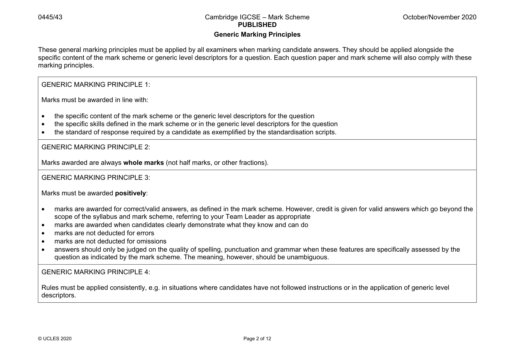
1 Circle two infinite energy sources from the list below. coal wind oil solar natural gas [2]
Mark scheme: 1 coal wind oil solar natural gas 1 mark for each correct. 2 No marks if more than two are circled.
Q2 · State one advantage of using CAD/CAM in batch production
2 (a) State one advantage of using CAD/CAM in batch production. ................................................................................................................................................... .............................................................................................................................................. [1] (b) Name one manufacturing machine that can be controlled by a computer. .............................................................................................................................................. [1]
Mark scheme: 2(a) Advantages of CAD/CAM in batch production could be: • Repeatability • Reduced set-up time • Accuracy • Reduced labour costs. 1 mark. 1 Allow any other valid alternative ‘Quicker’, ‘easier’, ‘cheaper’, ‘reliable’ must be justified for a mark. 2(b) Any CNC machine, lathe, milling machine router, laser cutter, drill, vinyl cutter, 3D printer, 1 mark. 1 Allow any other valid alternative.
Q3 · A concrete beam used in a road bridge
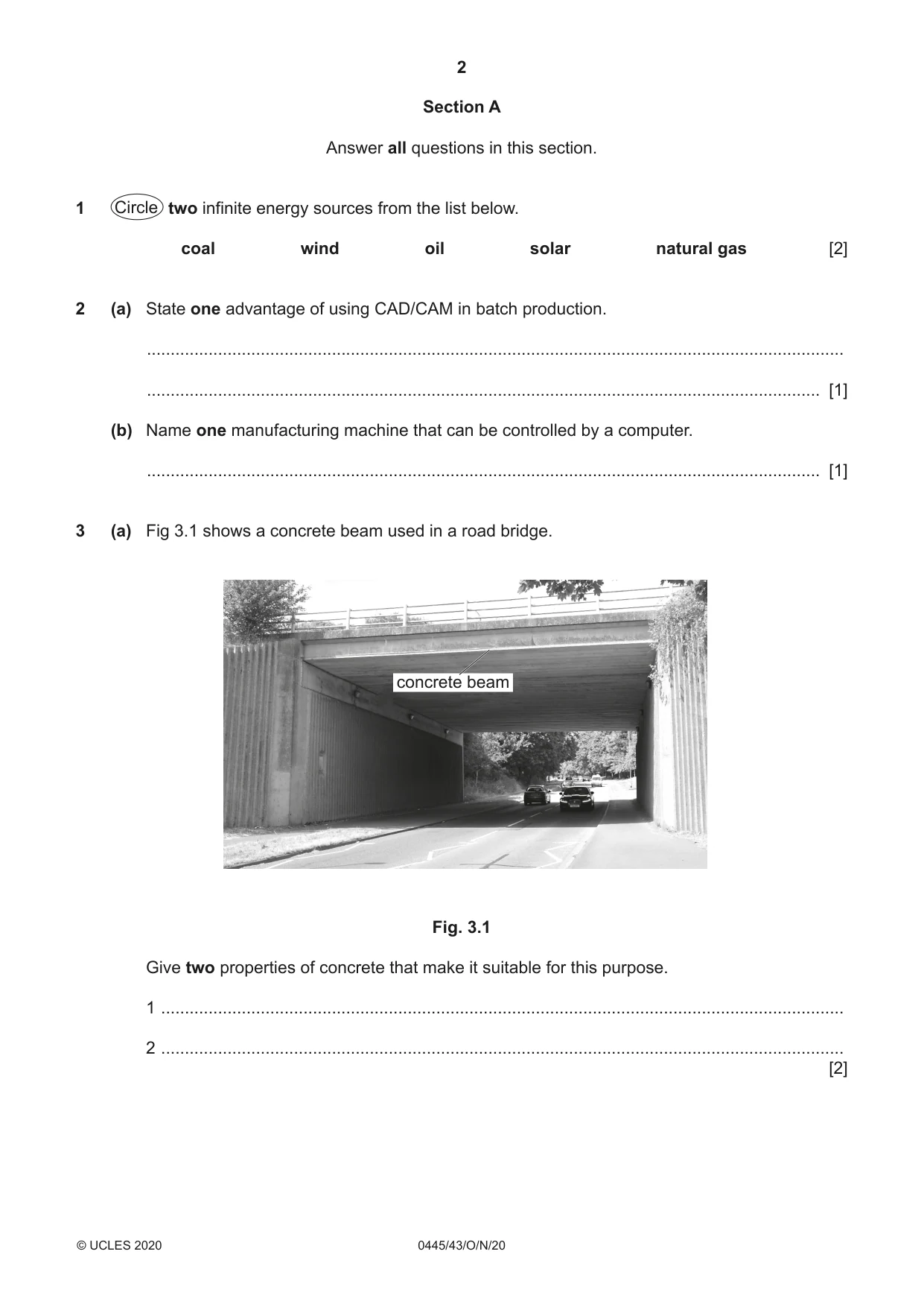
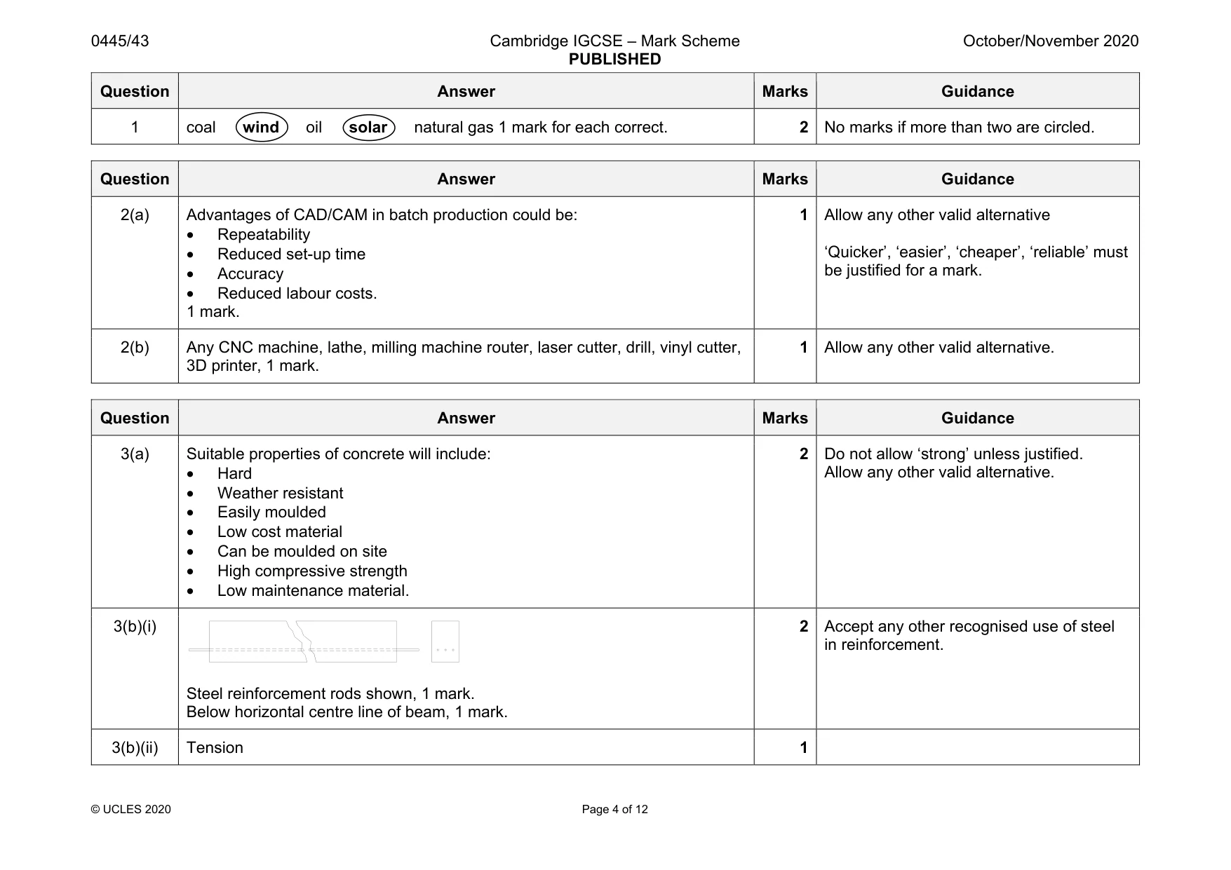
3 (a) Fig 3.1 shows a concrete beam used in a road bridge. concrete beam Fig. 3.1 Give two properties of concrete that make it suitable for this purpose. 1 ................................................................................................................................................ 2 ................................................................................................................................................ [2] (b) (i) Use sketches and notes to show how steel can be used to reinforce a concrete beam. [2] (ii) Name the main force resisted by steel in a concrete beam. ..................................................................................................................................... [1]
Mark scheme: 3(a) Suitable properties of concrete will include: • Hard • Weather resistant • Easily moulded • Low cost material • Can be moulded on site • High compressive strength • Low maintenance material. Allow any other valid alternative. 3(b)(i) Steel reinforcement rods shown, 1 mark. Below horizontal centre line of beam, 1 mark. 2 Accept any other recognised use of steel in reinforcement. 3(b)(ii) Tension 1
Q4 · Details of a self-grip wrench being locked onto a nut between the jaws
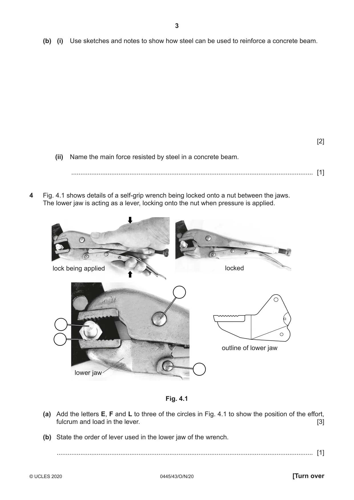
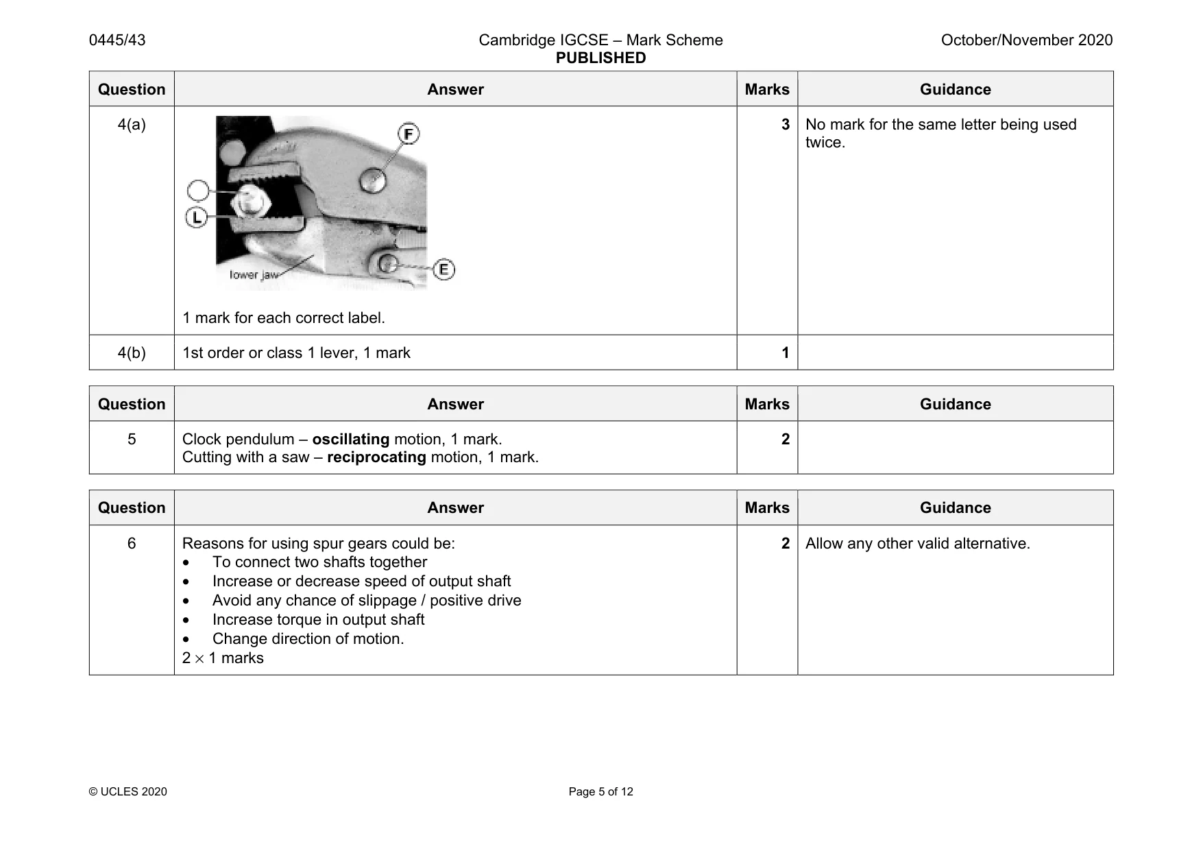
4 Fig. 4.1 shows details of a self-grip wrench being locked onto a nut between the jaws. The lower jaw is acting as a lever, locking onto the nut when pressure is applied. lock being applied locked outline of lower jaw lower jaw Fig. 4.1 (a) Add the letters E, F and L to three of the circles in Fig. 4.1 to show the position of the effort, fulcrum and load in the lever. [3] (b) State the order of lever used in the lower jaw of the wrench. ............................................................................................................................................. [1]
Mark scheme: 4(a) 1 mark for each correct label. 3 No mark for the same letter being used twice. 4(b) 1st order or class 1 lever, 1 mark 1
Q5 · State the type of motion which occurs in the following examples
5 State the type of motion which occurs in the following examples. Clock pendulum ............................................................................................................................... Cutting with a hacksaw .................................................................................................................... [2]
Mark scheme: 5 Clock pendulum – oscillating motion, 1 mark. Cutting with a saw – reciprocating motion, 1 mark. 2
Q6 · Give two reasons for using spur gears to transmit motion in a mechanism
6 Give two reasons for using spur gears to transmit motion in a mechanism. 1 ....................................................................................................................................................... .......................................................................................................................................................... 2 ....................................................................................................................................................... .......................................................................................................................................................... [2]
Mark scheme: 6 Reasons for using spur gears could be: • To connect two shafts together • Increase or decrease speed of output shaft • Avoid any chance of slippage / positive drive • Increase torque in output shaft • Change direction of motion. 2 × 1 marks 2 Allow any other valid alternative.
Q7 · A reed switch and the symbol for the switch
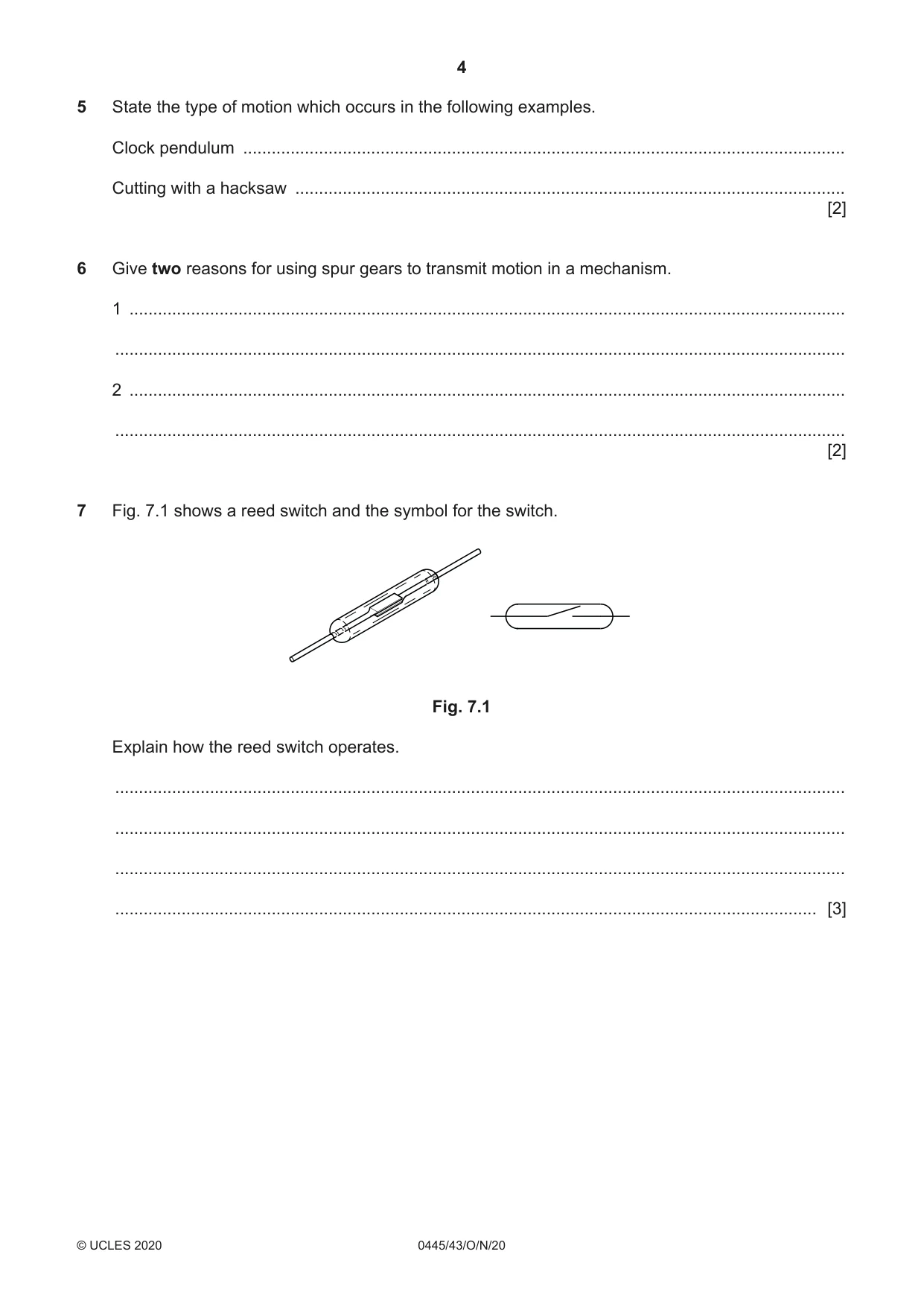
7 Fig. 7.1 shows a reed switch and the symbol for the switch. Fig. 7.1 Explain how the reed switch operates. .......................................................................................................................................................... .......................................................................................................................................................... .......................................................................................................................................................... .................................................................................................................................................... [3]
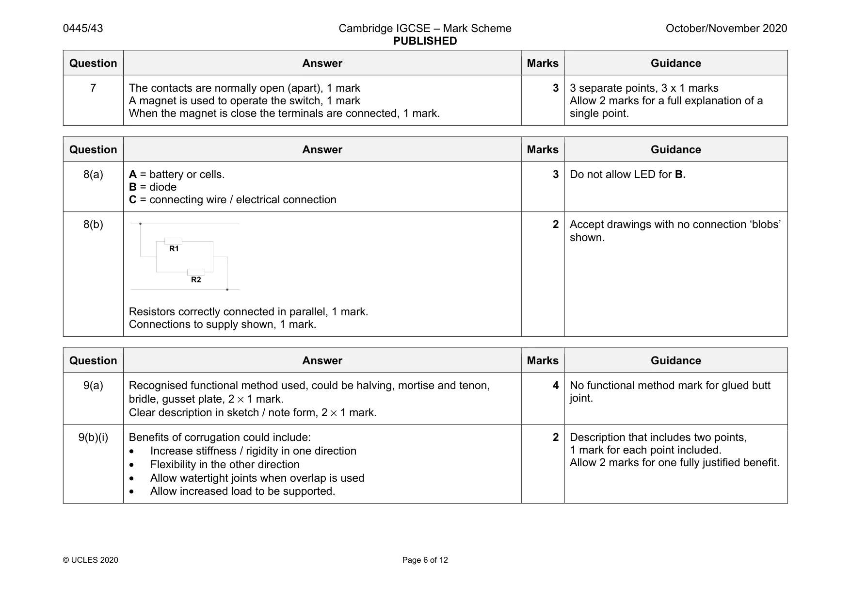
Mark scheme: 7 The contacts are normally open (apart), 1 mark A magnet is used to operate the switch, 1 mark When the magnet is close the terminals are connected, 1 mark. 3 3 separate points, 3 x 1 marks Allow 2 marks for a full explanation of a single point.
Q8 · Part of a circuit diagram
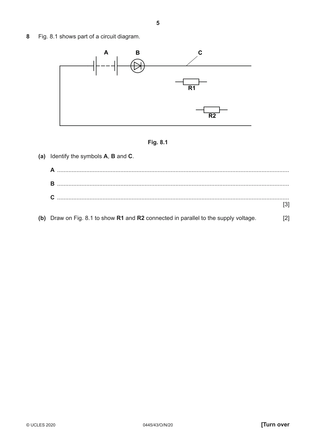
8 Fig. 8.1 shows part of a circuit diagram. A B C R1 R2 Fig. 8.1 (a) Identify the symbols A, B and C. A ............................................................................................................................................... B ............................................................................................................................................... C ............................................................................................................................................... [3] (b) Draw on Fig. 8.1 to show R1 and R2 connected in parallel to the supply voltage. [2]
Mark scheme: 8(a) A = battery or cells. B = diode C = connecting wire / electrical connection 3 Do not allow LED for B. 8(b) Resistors correctly connected in parallel, 1 mark. Connections to supply shown, 1 mark. 2 Accept drawings with no connection ‘blobs’ shown. R2 R1
Q9 · Two lengths of softwood that are to be joined at 90° to each other
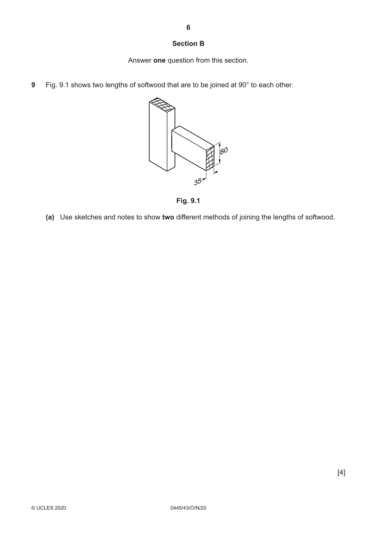
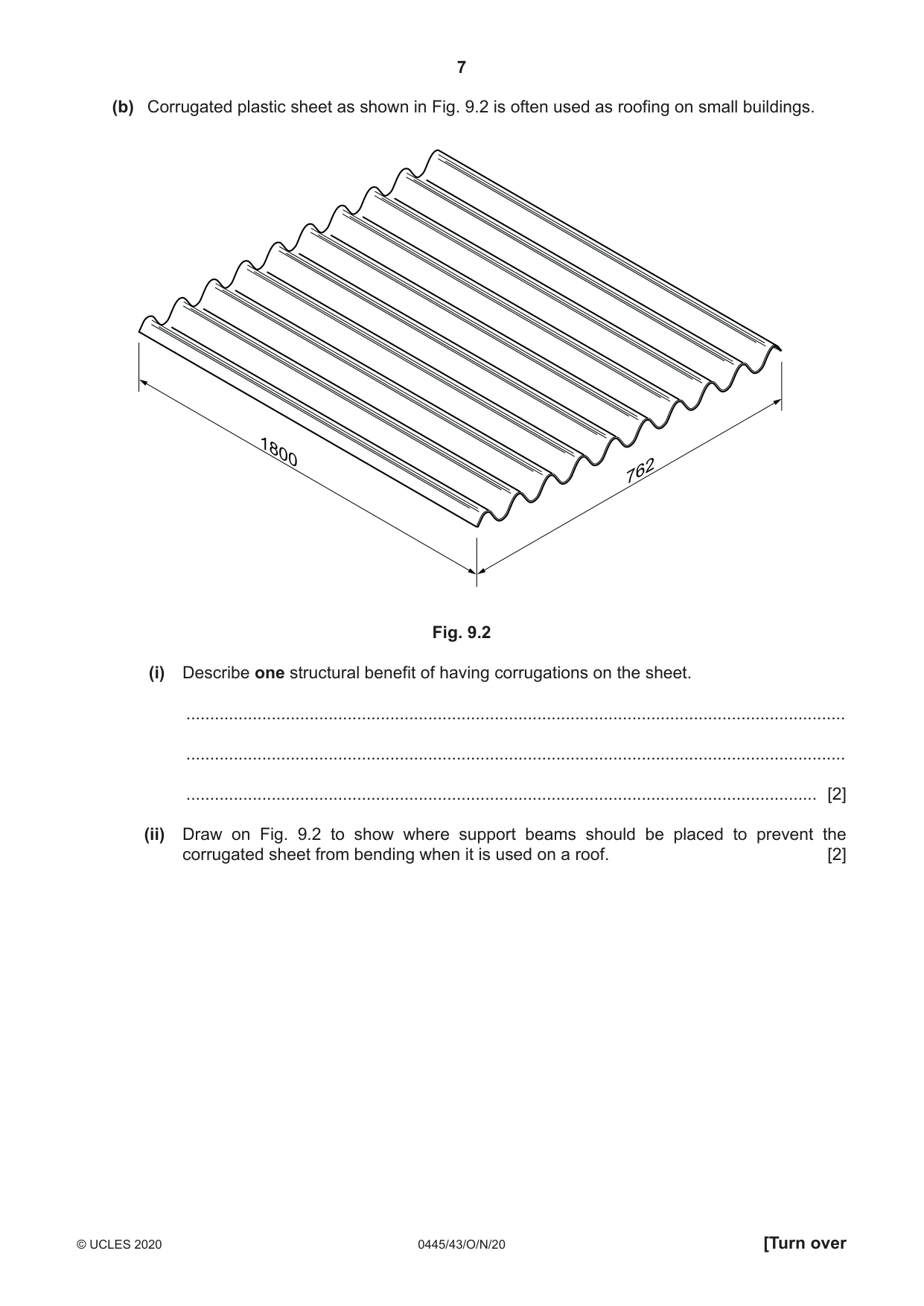
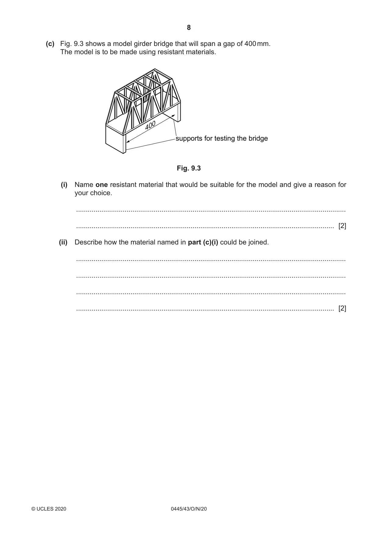
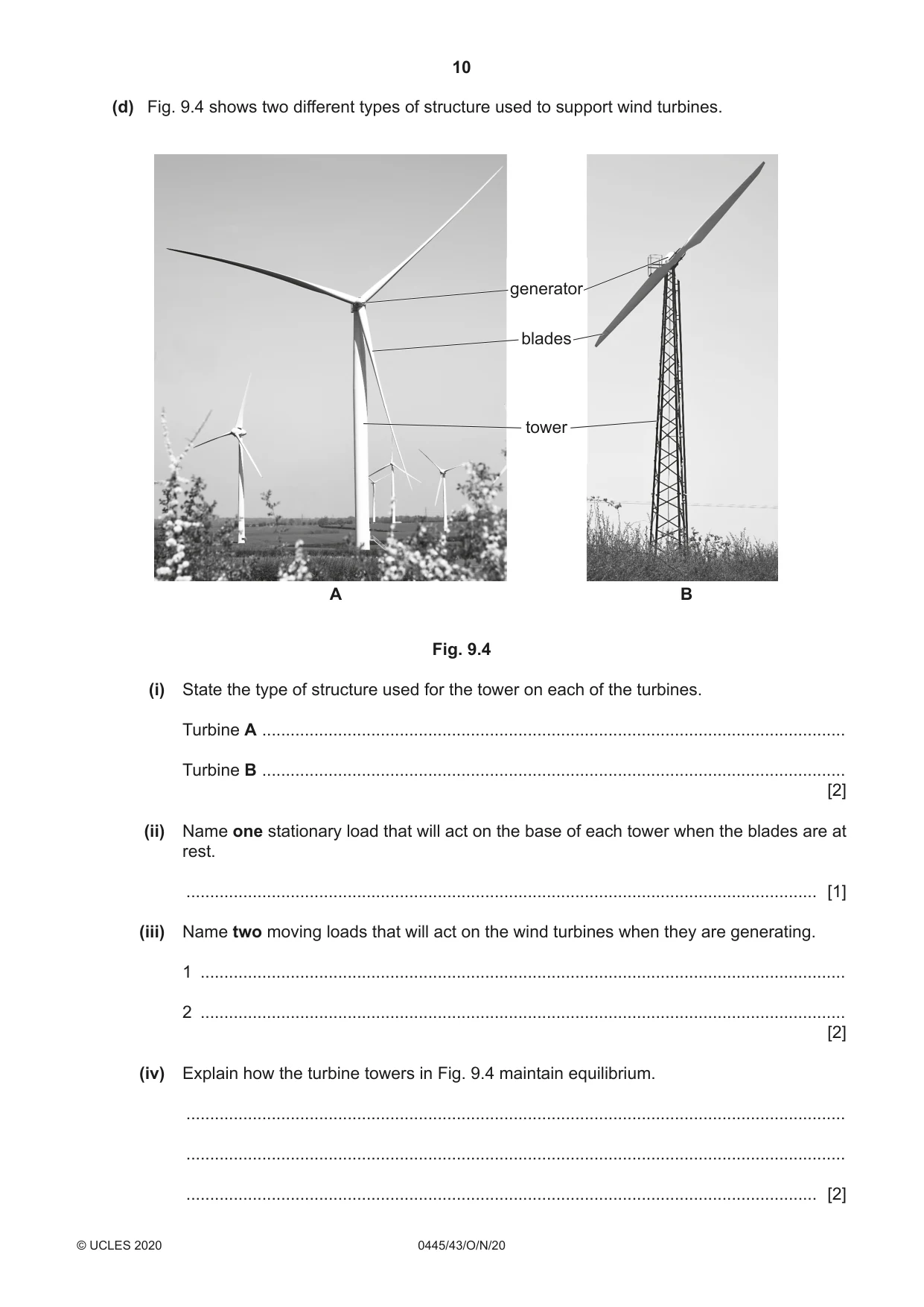
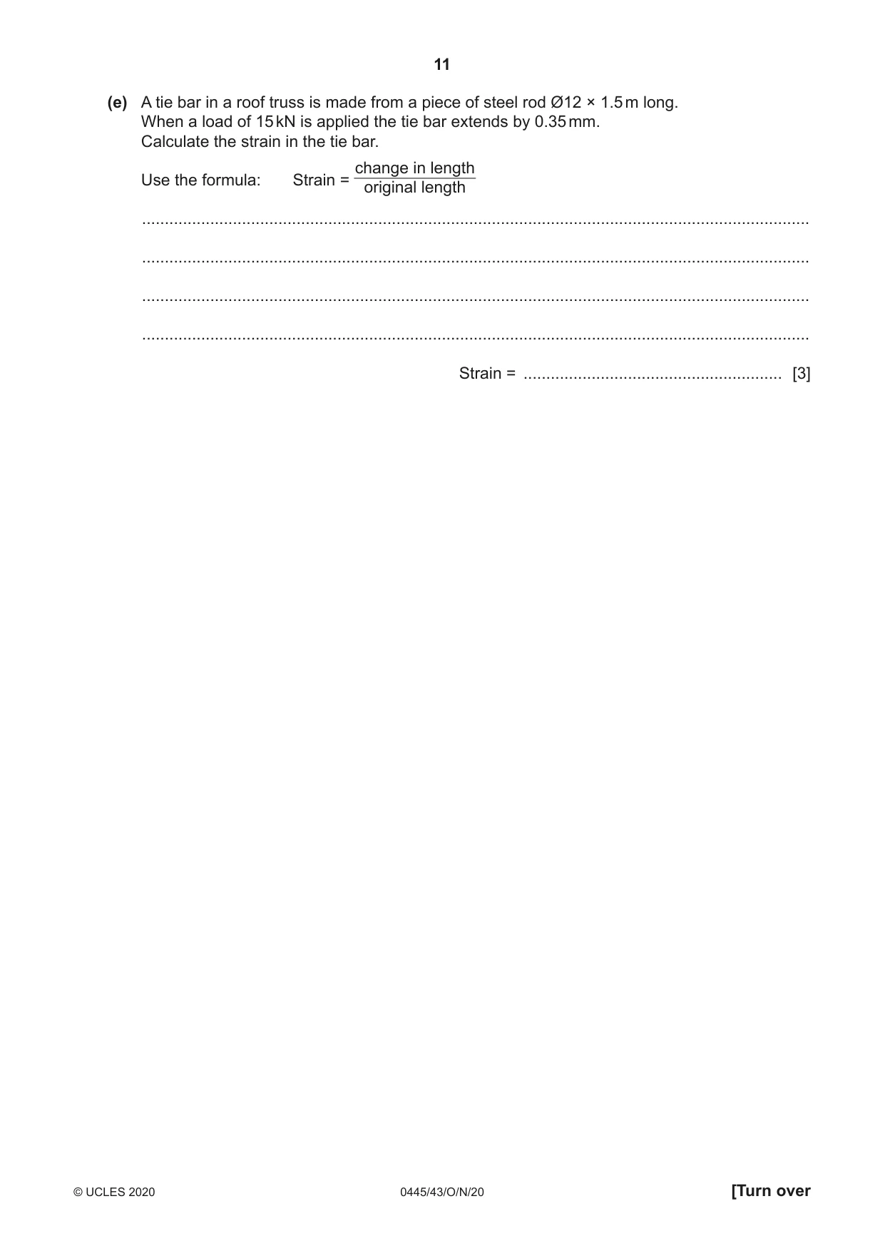
9 Fig. 9.1 shows two lengths of softwood that are to be joined at 90° to each other. 80 35 Fig. 9.1 (a) Use sketches and notes to show two different methods of joining the lengths of softwood. [4] (b) Corrugated plastic sheet as shown in Fig. 9.2 is often used as roofing on small buildings. 1800 762 Fig. 9.2 (i) Describe one structural benefit of having corrugations on the sheet. ........................................................................................................................................... ........................................................................................................................................... ..................................................................................................................................... [2] (ii) Draw on Fig. 9.2 to show where support beams should be placed to prevent the corrugated sheet from bending when it is used on a roof. [2] (c) Fig. 9.3 shows a model girder bridge that will span a gap of 400 mm. The model is to be made using resistant materials. 400 supports for testing the bridge Fig. 9.3 (i) Name one resistant material that would be suitable for the model and give a reason for your choice. ........................................................................................................................................... ..................................................................................................................................... [2] (ii) Describe how the material named in part (c)(i) could be joined. ........................................................................................................................................... ........................................................................................................................................... ........................................................................................................................................... ..................................................................................................................................... [2] (iii) Use sketches and notes to show how the model could be tested and evaluated. [3] (d) Fig. 9.4 shows two different types of structure used to support wind turbines. generator blades tower A B Fig. 9.4 (i) State the type of structure used for the tower on each of the turbines. Turbine A ........................................................................................................................... Turbine B ........................................................................................................................... [2] (ii) Name one stationary load that will act on the base of each tower when the blades are at rest. ..................................................................................................................................... [1] (iii) Name two moving loads that will act on the wind turbines when they are generating. 1 ........................................................................................................................................ 2 ........................................................................................................................................ [2] (iv) Explain how the turbine towers in Fig. 9.4 maintain equilibrium. ........................................................................................................................................... ........................................................................................................................................... ..................................................................................................................................... [2] (e) A tie bar in a roof truss is made from a piece of steel rod Ø12 × 1.5 m long. When a load of 15 kN is applied the tie bar extends by 0.35 mm. Calculate the strain in the tie bar. change in length Use the formula: Strain = original length ................................................................................................................................................... ................................................................................................................................................... ................................................................................................................................................... ................................................................................................................................................... Strain = ......................................................... [3]
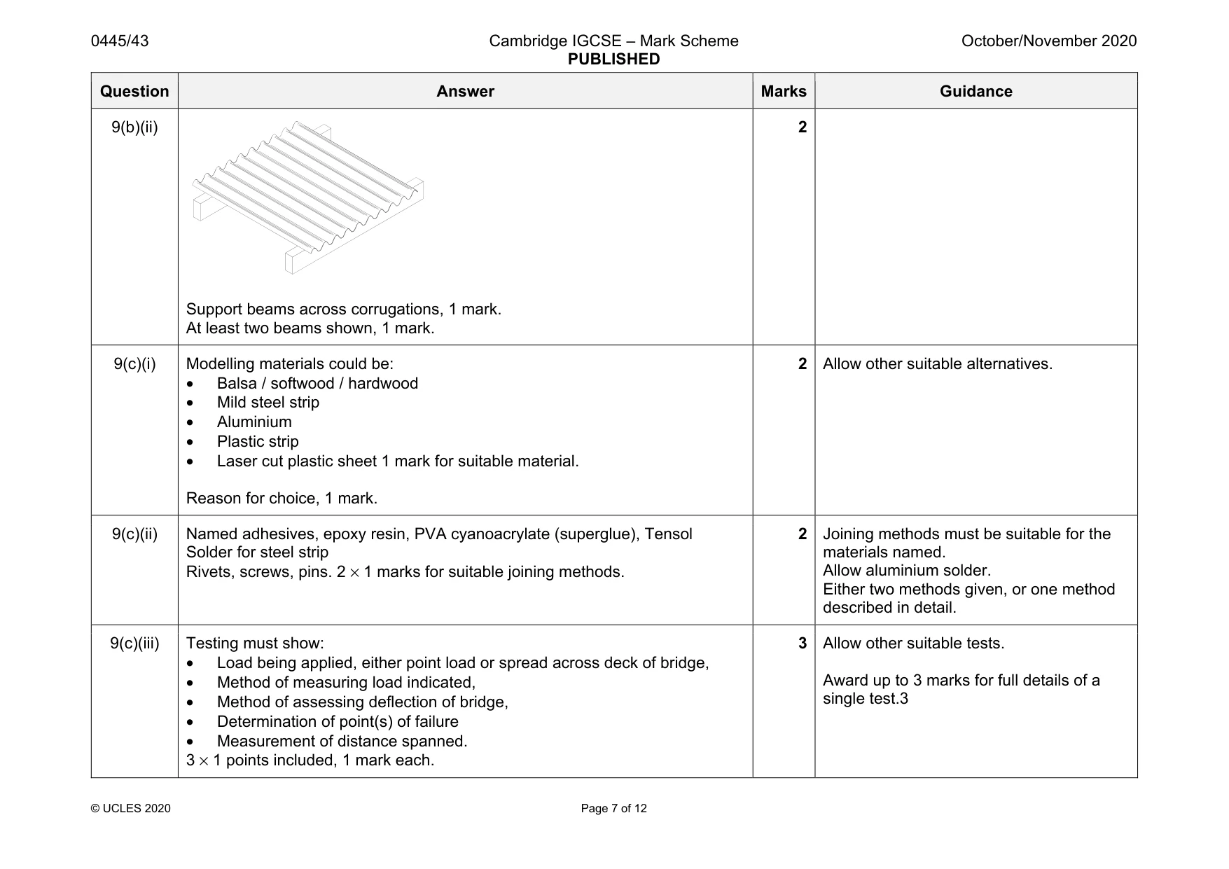
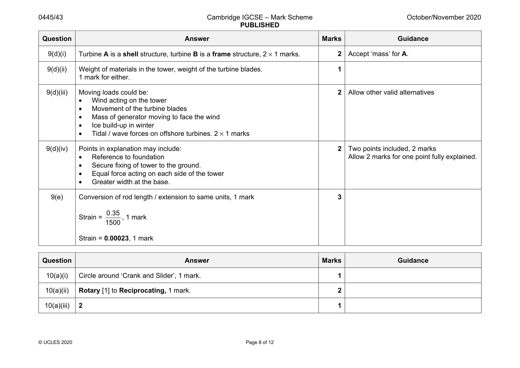
Mark scheme: 9(a) Recognised functional method used, could be halving, mortise and tenon, bridle, gusset plate, 2 × 1 mark. Clear description in sketch / note form, 2 × 1 mark. joint. 9(b)(i) Benefits of corrugation could include: • Increase stiffness / rigidity in one direction • Flexibility in the other direction • Allow watertight joints when overlap is used • Allow increased load to be supported. 2 Description that includes two points, 1 mark for each point included. Allow 2 marks for one fully justified benefit. Question Answer Marks Guidance 9(b)(ii) Support beams across corrugations, 1 mark. At least two beams shown, 1 mark. 2 9(c)(i) Modelling materials could be: • Balsa / softwood / hardwood • Mild steel strip • Aluminium • Plastic strip • Laser cut plastic sheet 1 mark for suitable material. Reason for choice, 1 mark. 2 Allow other suitable alternatives. 9(c)(ii) Named adhesives, epoxy resin, PVA cyanoacrylate (superglue), Tensol Solder for steel strip Rivets, screws, pins. 2 × 1 marks for suitable joining methods. 2 Joining methods must be suitable for the materials named. Allow aluminium solder. Either two methods given, or one method described in detail. 9(c)(iii) Testing must show: • Load being applied, either point load or spread across deck of bridge, • Method of measuring load indicated, • Method of assessing deflection of bridge, • Determination of point(s) of failure • Measurement of distance spanned. 3 × 1 points included, 1 mark each. 3 Allow other suitable tests. Award up to 3 marks for full details of a single test.3 Question Answer Marks Guidance 9(d)(i) Turbine A is a shell structure, turbine B is a frame structure, 2 × 1 marks. 2 Accept ‘mass’ for A. 9(d)(ii) Weight of materials in the tower, weight of the turbine blades. 1 mark for either. 1 9(d)(iii) Moving loads could be: • Wind acting on the tower • Movement of the turbine blades • Mass of generator moving to face the wind • Ice build-up in winter • Tidal / wave forces on offshore turbines. 2 × 1 marks 2 Allow other valid alternatives 9(d)(iv) Points in explanation may include: • Reference to foundation • Secure fixing of tower to the ground. • Equal force acting on each side of the tower • Greater width at the base. 2 Two points included, 2 marks Allow 2 marks for one point fully explained. 9(e) Conversion of rod length / extension to same units, 1 mark Strain = 0.35 1500 , 1 mark Strain = 0.00023, 1 mark 3
Q10 · A toy steam locomotive
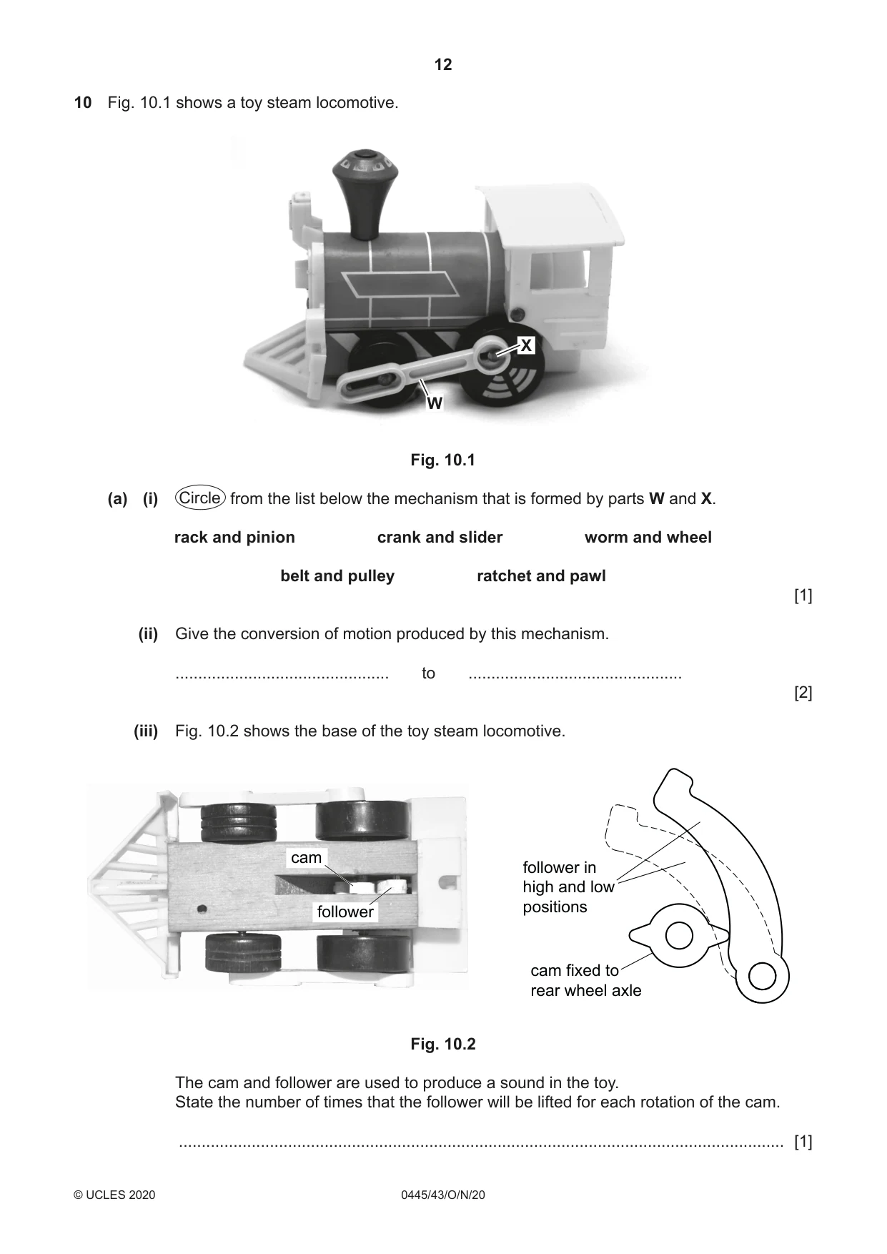
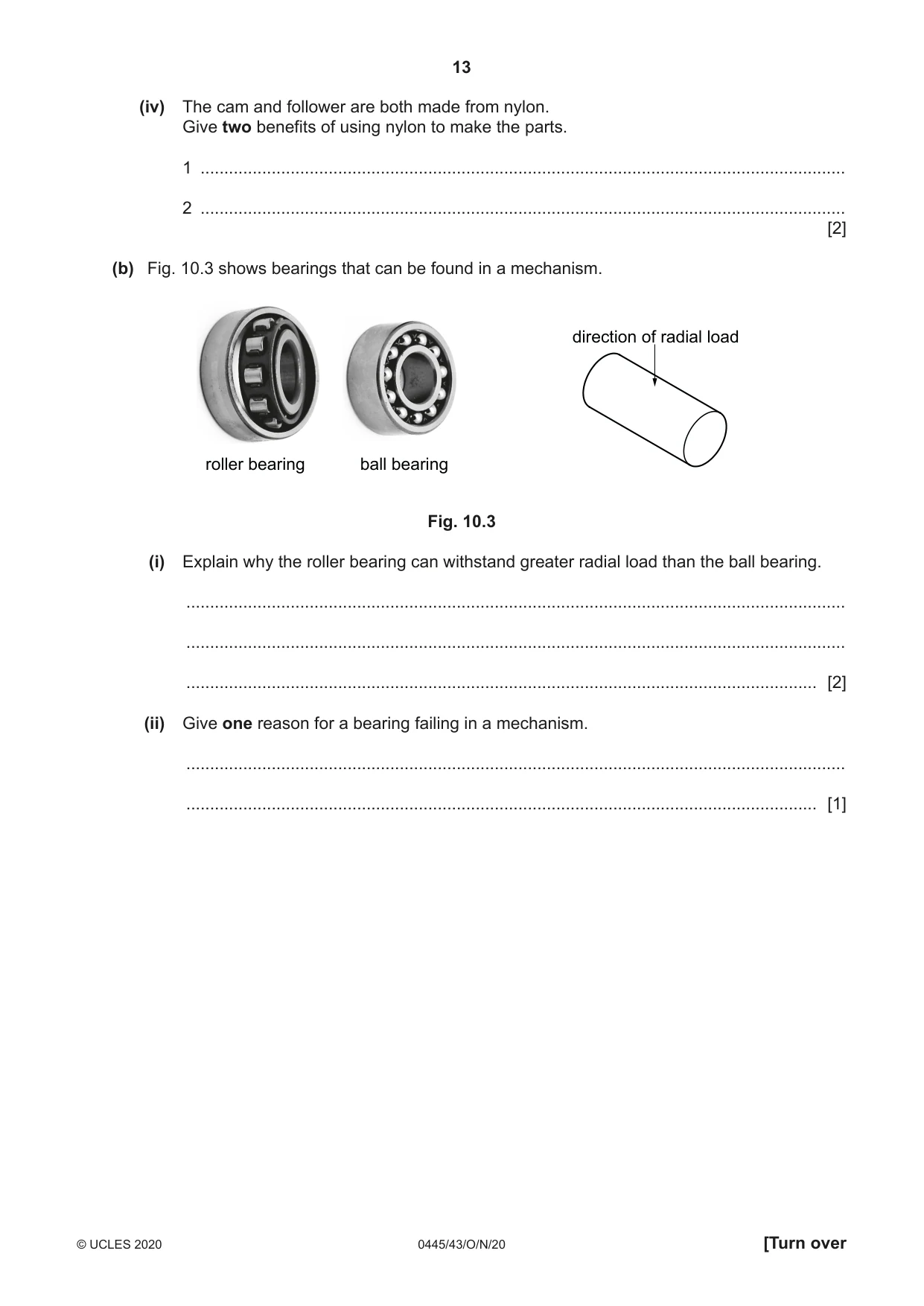
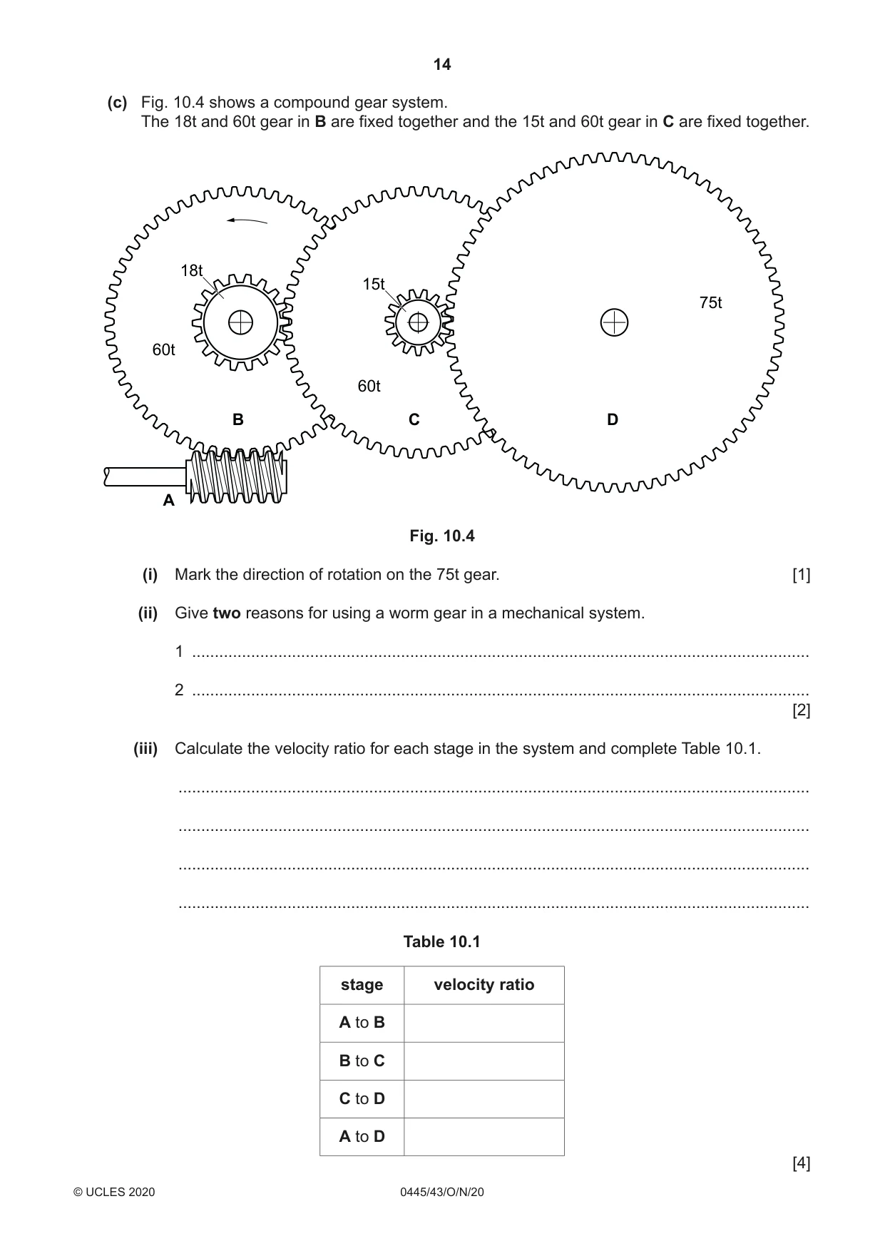
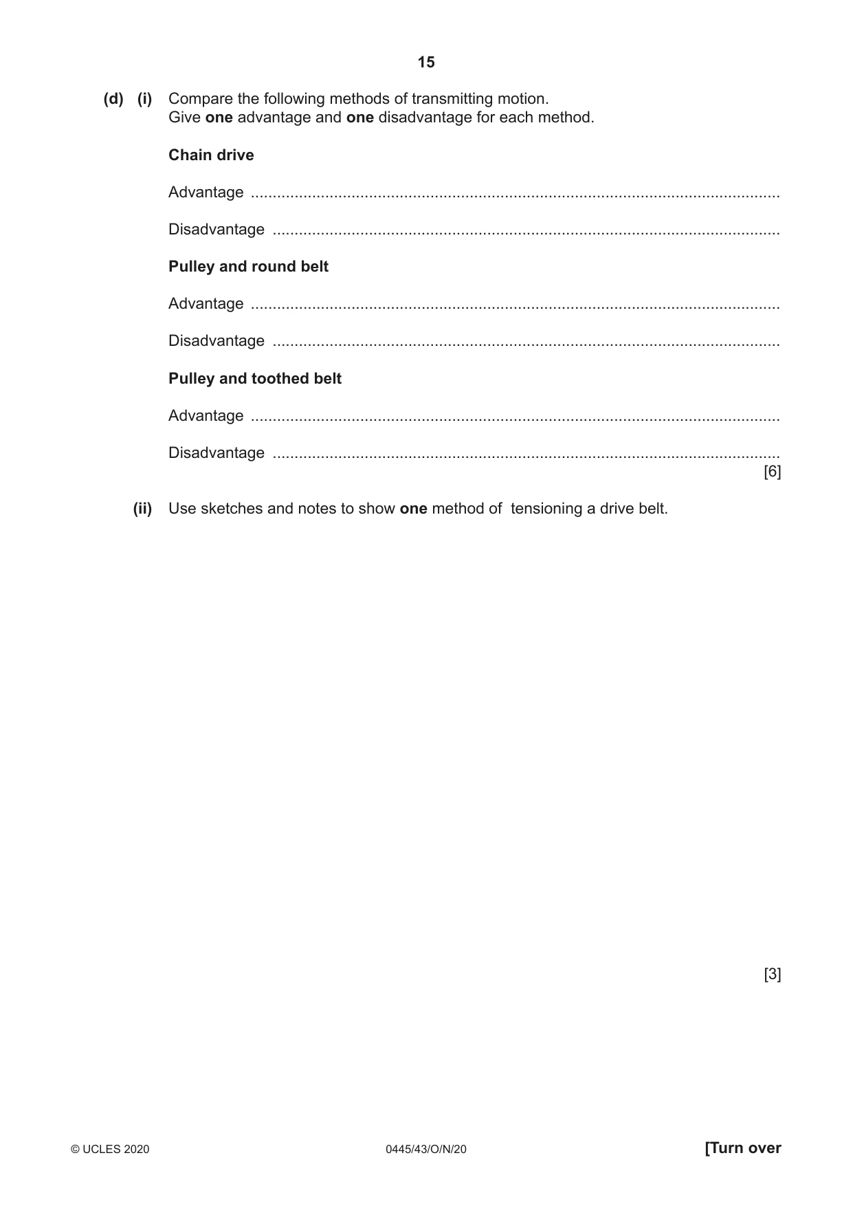
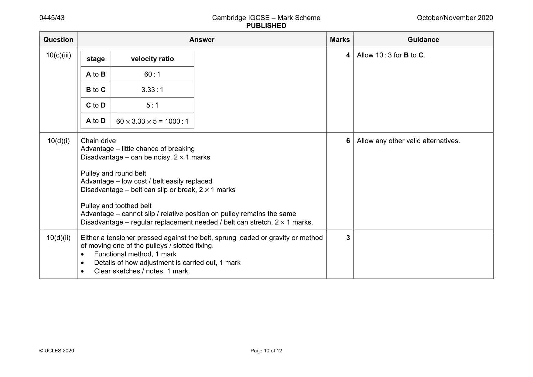
10 Fig. 10.1 shows a toy steam locomotive. X W Fig. 10.1 (a) (i) Circle from the list below the mechanism that is formed by parts W and X. rack and pinion crank and slider worm and wheel belt and pulley ratchet and pawl [1] (ii) Give the conversion of motion produced by this mechanism. ............................................... to ............................................... [2] (iii) Fig. 10.2 shows the base of the toy steam locomotive. cam follower in high and low positions follower cam fixed to rear wheel axle Fig. 10.2 The cam and follower are used to produce a sound in the toy. State the number of times that the follower will be lifted for each rotation of the cam. ..................................................................................................................................... [1] (iv) The cam and follower are both made from nylon. Give two benefits of using nylon to make the parts. 1 ........................................................................................................................................ 2 ........................................................................................................................................ [2] (b) Fig. 10.3 shows bearings that can be found in a mechanism. direction of radial load roller bearing ball bearing Fig. 10.3 (i) Explain why the roller bearing can withstand greater radial load than the ball bearing. ........................................................................................................................................... ........................................................................................................................................... ..................................................................................................................................... [2] (ii) Give one reason for a bearing failing in a mechanism. ........................................................................................................................................... ..................................................................................................................................... [1] (c) Fig. 10.4 shows a compound gear system. The 18t and 60t gear in B are fixed together and the 15t and 60t gear in C are fixed together. 18t 15t 75t 60t 60t B C D A Fig. 10.4 (i) Mark the direction of rotation on the 75t gear. [1] (ii) Give two reasons for using a worm gear in a mechanical system. 1 ........................................................................................................................................ 2 ........................................................................................................................................ [2] (iii) Calculate the velocity ratio for each stage in the system and complete Table 10.1. ........................................................................................................................................... ........................................................................................................................................... ........................................................................................................................................... ........................................................................................................................................... Table 10.1 stage velocity ratio A to B B to C C to D A to D [4] (d) (i) Compare the following methods of transmitting motion. Give one advantage and one disadvantage for each method. Chain drive Advantage ......................................................................................................................... Disadvantage .................................................................................................................... Pulley and round belt Advantage ......................................................................................................................... Disadvantage .................................................................................................................... Pulley and toothed belt Advantage ......................................................................................................................... Disadvantage .................................................................................................................... [6] (ii) Use sketches and notes to show one method of tensioning a drive belt. [3]
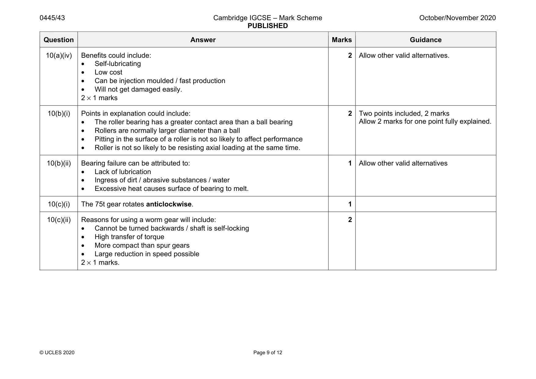
Mark scheme: 10(a)(i) Circle around ‘Crank and Slider’, 1 mark. 1 10(a)(ii) Rotary [1] to Reciprocating, 1 mark. 2 10(a)(iii) 2 1 Question Answer Marks Guidance 10(a)(iv) Benefits could include: • Self-lubricating • Low cost • Can be injection moulded / fast production • Will not get damaged easily. 2 × 1 marks 2 Allow other valid alternatives. 10(b)(i) Points in explanation could include: • The roller bearing has a greater contact area than a ball bearing • Rollers are normally larger diameter than a ball • Pitting in the surface of a roller is not so likely to affect performance • Roller is not so likely to be resisting axial loading at the same time. 2 Two points included, 2 marks Allow 2 marks for one point fully explained. 10(b)(ii) Bearing failure can be attributed to: • Lack of lubrication • Ingress of dirt / abrasive substances / water • Excessive heat causes surface of bearing to melt. 1 Allow other valid alternatives 10(c)(i) The 75t gear rotates anticlockwise. 1 10(c)(ii) Reasons for using a worm gear will include: • Cannot be turned backwards / shaft is self-locking • High transfer of torque • More compact than spur gears • Large reduction in speed possible 2 × 1 marks. 2 Question Answer Marks Guidance 10(c)(iii) stage velocity ratio A to B 60 : 1 B to C 3.33 : 1 C to D 5 : 1 A to D 60 × 3.33 × 5 = 1000 : 1 4 Allow 10 : 3 for B to C. 10(d)(i) Chain drive Advantage – little chance of breaking Disadvantage – can be noisy, 2 × 1 marks Pulley and round belt Advantage – low cost / belt easily replaced Disadvantage – belt can slip or break, 2 × 1 marks Pulley and toothed belt Advantage – cannot slip / relative position on pulley remains the same Disadvantage – regular replacement needed / belt can stretch, 2 × 1 marks. 6 Allow any other valid alternatives. 10(d)(ii) Either a tensioner pressed against the belt, sprung loaded or gravity or method of moving one of the pulleys / slotted fixing. • Functional method, 1 mark • Details of how adjustment is carried out, 1 mark • Clear sketches / notes, 1 mark. 3
Q11 · Two methods of connection to a circuit board that do not require soldering
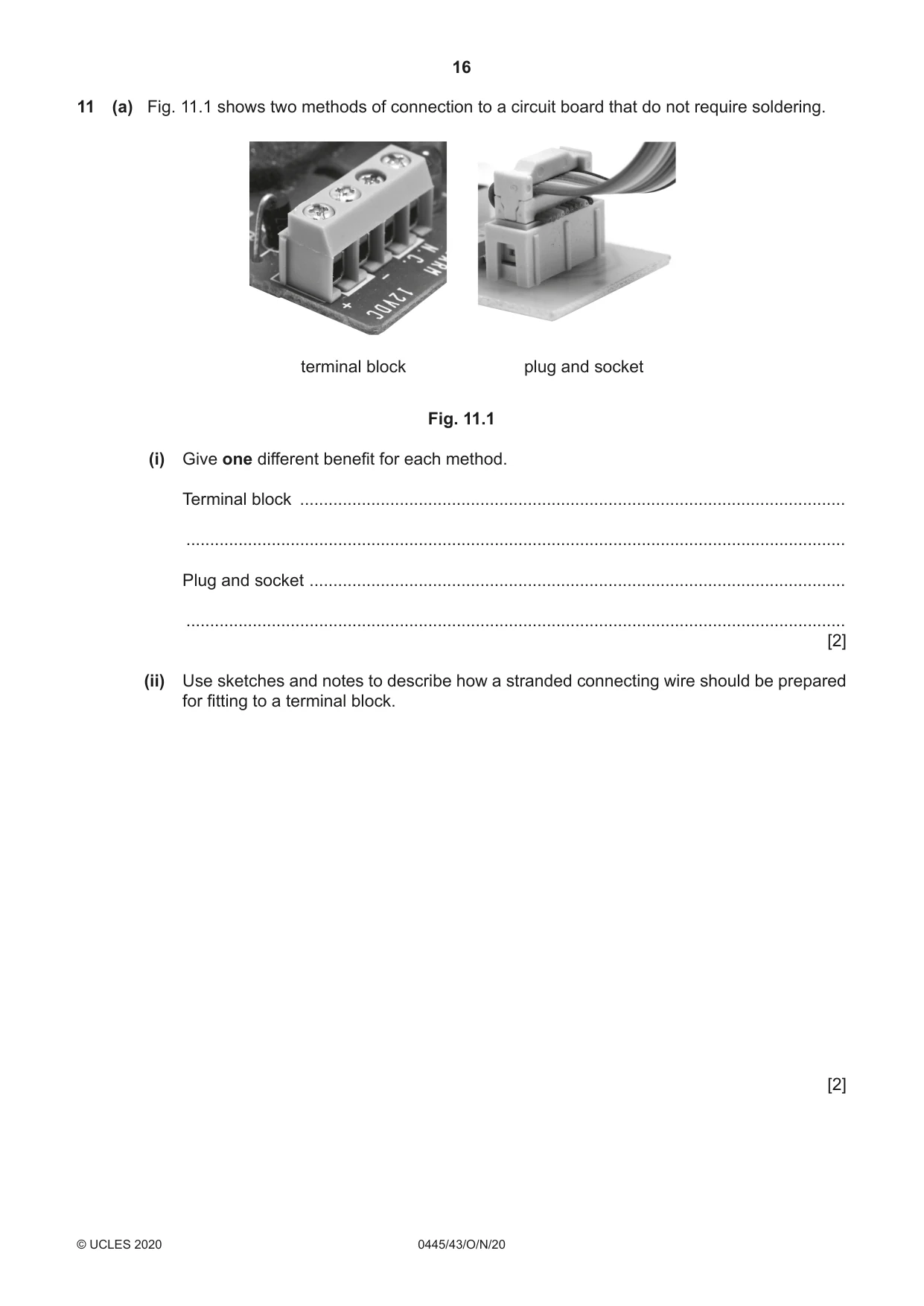
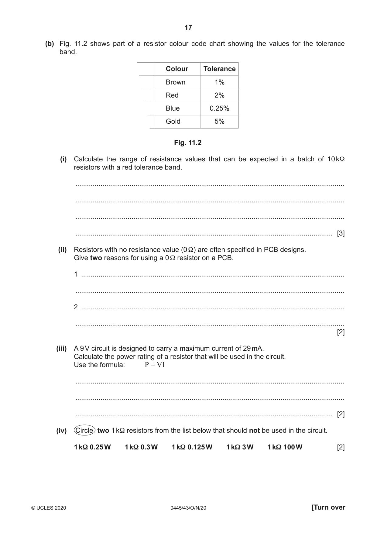
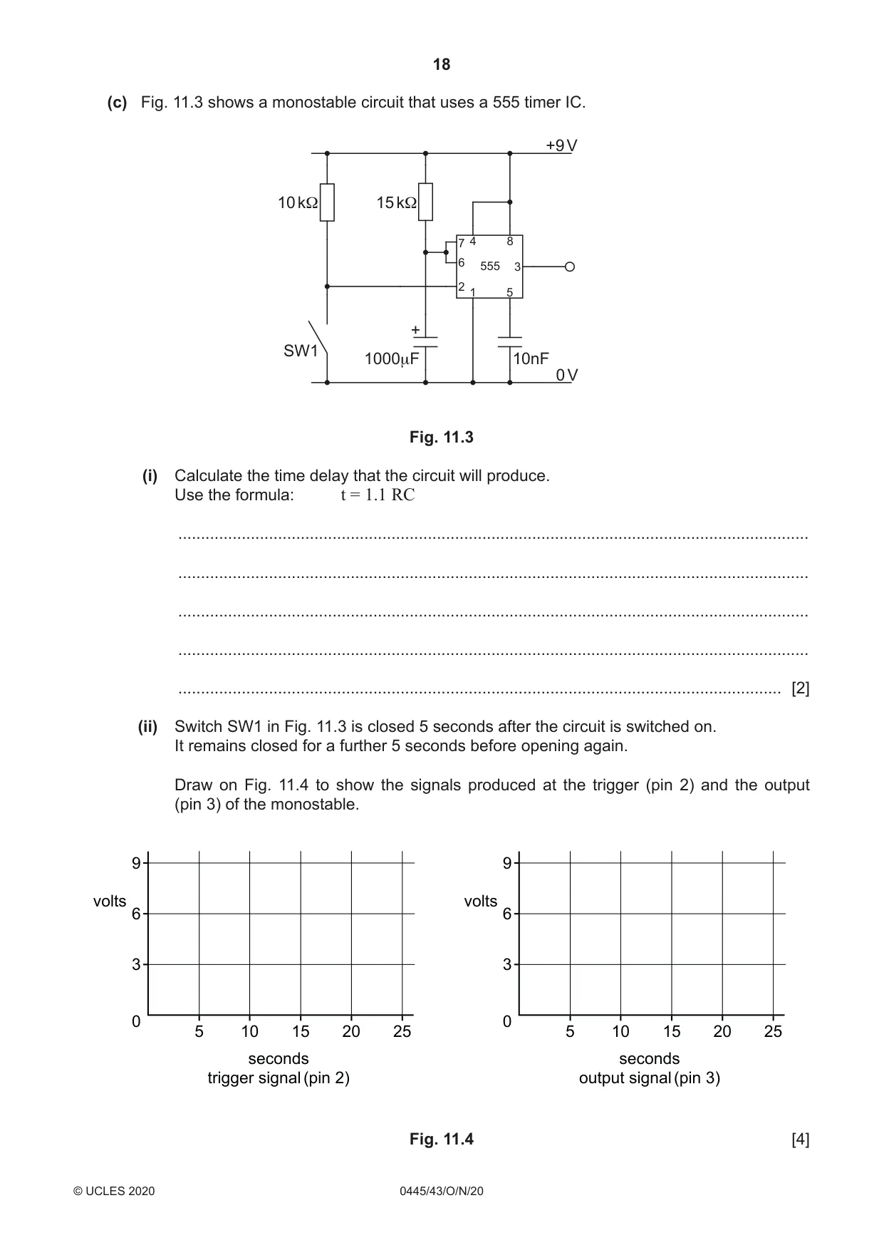
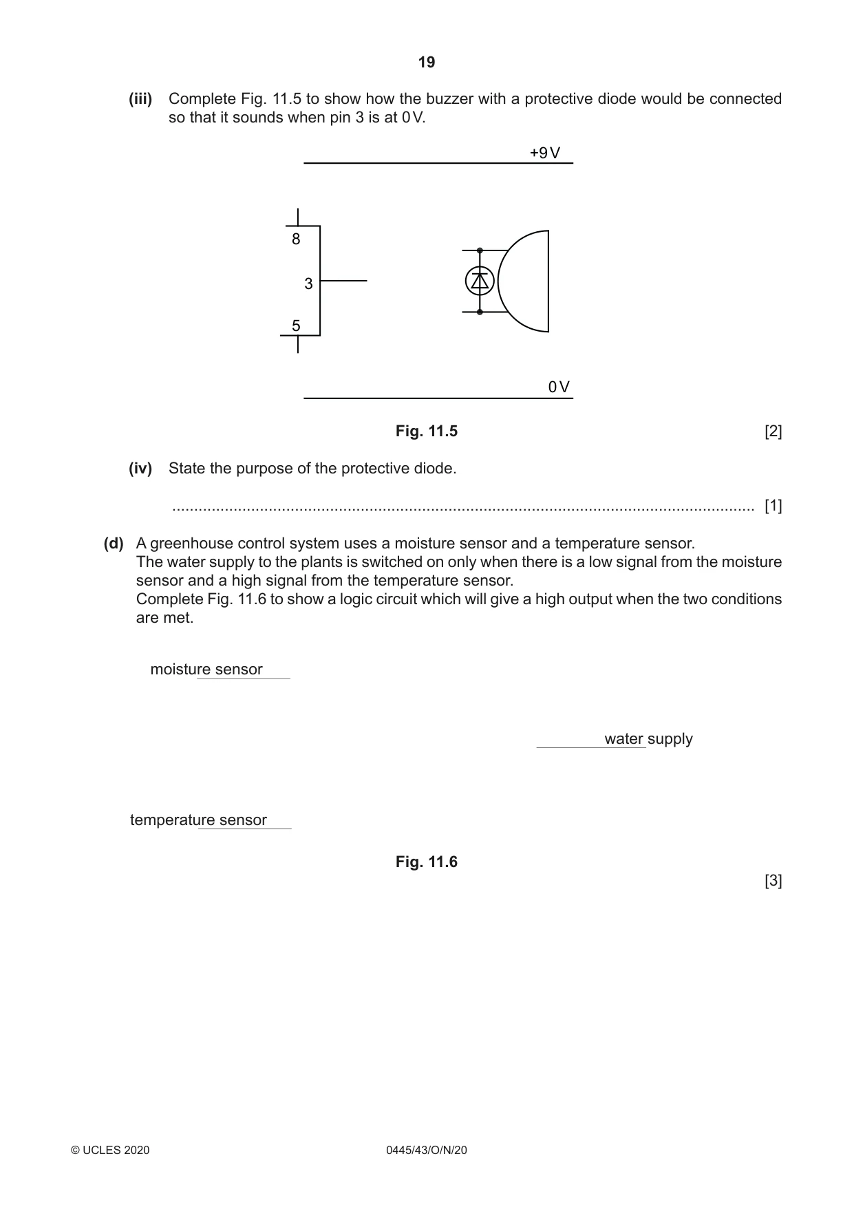
11 (a) Fig. 11.1 shows two methods of connection to a circuit board that do not require soldering. terminal block plug and socket Fig. 11.1 (i) Give one different benefit for each method. Terminal block ................................................................................................................... ........................................................................................................................................... Plug and socket ................................................................................................................. ........................................................................................................................................... [2] (ii) Use sketches and notes to describe how a stranded connecting wire should be prepared for fitting to a terminal block. [2] (b) Fig. 11.2 shows part of a resistor colour code chart showing the values for the tolerance band. Colour Tolerance Brown 1% Red 2% Blue 0.25% Gold 5% Fig. 11.2 (i) Calculate the range of resistance values that can be expected in a batch of 10 kΩ resistors with a red tolerance band. ........................................................................................................................................... ........................................................................................................................................... ........................................................................................................................................... ..................................................................................................................................... [3] (ii) Resistors with no resistance value (0 Ω) are often specified in PCB designs. Give two reasons for using a 0 Ω resistor on a PCB. 1 ........................................................................................................................................ ........................................................................................................................................... 2 ........................................................................................................................................ ........................................................................................................................................... [2] (iii) A 9 V circuit is designed to carry a maximum current of 29 mA. Calculate the power rating of a resistor that will be used in the circuit. Use the formula: P = VI ........................................................................................................................................... ........................................................................................................................................... ..................................................................................................................................... [2] (iv) Circle two 1 kΩ resistors from the list below that should not be used in the circuit. 1 kΩ 0.25 W 1 kΩ 0.3 W 1 kΩ 0.125 W 1 kΩ 3 W 1 kΩ 100 W [2] (c) Fig. 11.3 shows a monostable circuit that uses a 555 timer IC. +9 V 10 kΩ 15 kΩ 7 4 8 6 555 3 2 1 5 + SW1 1000μF 10nF 0 V Fig. 11.3 (i) Calculate the time delay that the circuit will produce. Use the formula: t = 1.1 RC ........................................................................................................................................... ........................................................................................................................................... ........................................................................................................................................... ........................................................................................................................................... ..................................................................................................................................... [2] (ii) Switch SW1 in Fig. 11.3 is closed 5 seconds after the circuit is switched on. It remains closed for a further 5 seconds before opening again. Draw on Fig. 11.4 to show the signals produced at the trigger (pin 2) and the output (pin 3) of the monostable. 9 9 volts volts 6 6 3 3 0 0 5 10 15 20 25 5 10 15 20 25 seconds seconds trigger signal (pin 2) output signal (pin 3) Fig. 11.4 [4]
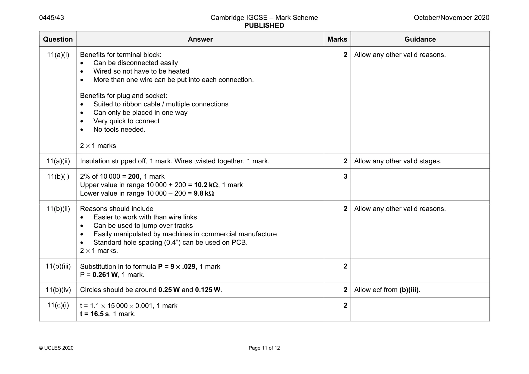
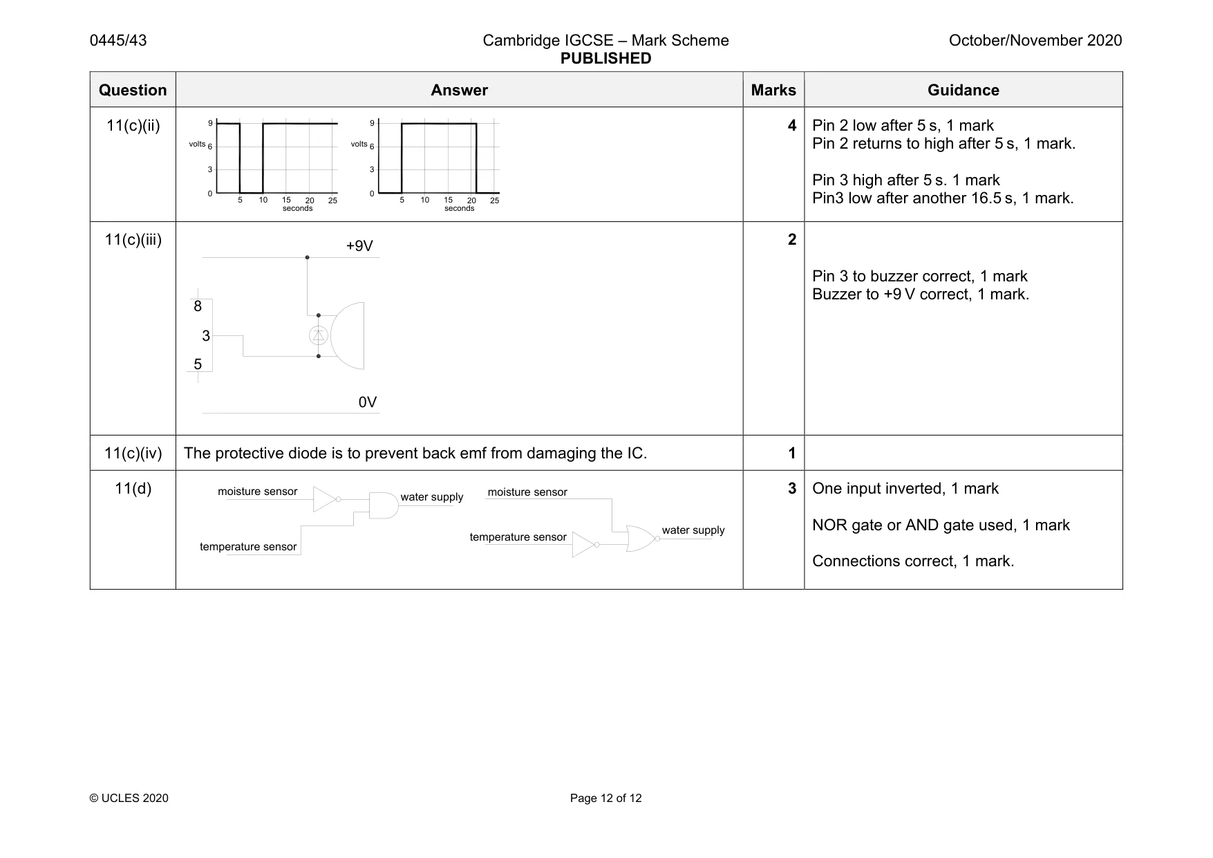
Mark scheme: 11(a)(i) Benefits for terminal block: • Can be disconnected easily • Wired so not have to be heated • More than one wire can be put into each connection. Benefits for plug and socket: • Suited to ribbon cable / multiple connections • Can only be placed in one way • Very quick to connect • No tools needed. 2 × 1 marks 2 Allow any other valid reasons. 11(a)(ii) Insulation stripped off, 1 mark. Wires twisted together, 1 mark. 2 Allow any other valid stages. 11(b)(i) 2% of 10 000 = 200, 1 mark Upper value in range 10 000 + 200 = 10.2 kΩ, 1 mark Lower value in range 10 000 – 200 = 9.8 kΩ 3 11(b)(ii) Reasons should include • Easier to work with than wire links • Can be used to jump over tracks • Easily manipulated by machines in commercial manufacture • Standard hole spacing (0.4”) can be used on PCB. 2 × 1 marks. 2 Allow any other valid reasons. 11(b)(iii) Substitution in to formula P = 9 × .029, 1 mark P = 0.261 W, 1 mark. 2 11(b)(iv) Circles should be around 0.25 W and 0.125 W. 2 Allow ecf from (b)(iii). 11(c)(i) t = 1.1 × 15 000 × 0.001, 1 mark t = 16.5 s, 1 mark. 2 Question Answer Marks Guidance 11(c)(ii) 4 Pin 2 low after 5 s, 1 mark Pin 2 returns to high after 5 s, 1 mark. Pin 3 high after 5 s. 1 mark Pin3 low after another 16.5 s, 1 mark. 11(c)(iii) 2 Pin 3 to buzzer correct, 1 mark Buzzer to +9 V correct, 1 mark. 11(c)(iv) The protective diode is to prevent back emf from damaging the IC. 1 11(d) 3 One input inverted, 1 mark NOR gate or AND gate used, 1 mark Connections correct, 1 mark. volts seconds 3 6 9 0 5 10 15 20 25 volts seconds 3 6 9 0 5 10 15 20 25 3 5 8 0V +9V moisture sensor temperature sensor water supply moisture sensor temperature sensor water supply
What was in this paper
The subtopics covered by these 11 questions, and how many questions each got. Open one in a new tab to see every Cambridge question on it.
What you needed in this session
Cambridge’s own grade thresholds for 2020 Oct/Nov, Paper 4 · Variant 3. A higher threshold means an easier paper — the bar moves with how the cohort did.