Cambridge IGCSE Design and Technology 0445 — 2019 Oct/Nov Paper 4 · Variant 1
0445/41/O/N/19 · 11 questions · 50 marks · ≈56 min
The question paper and its mark scheme, free to read here and free to download. This is Cambridge’s own paper, exactly as it was sat.
Question paper20 pages




Mark scheme14 pages
Answers below. Sit the paper first if you are practising.

Questions as text
Q1 · Models are often used when designing a structure
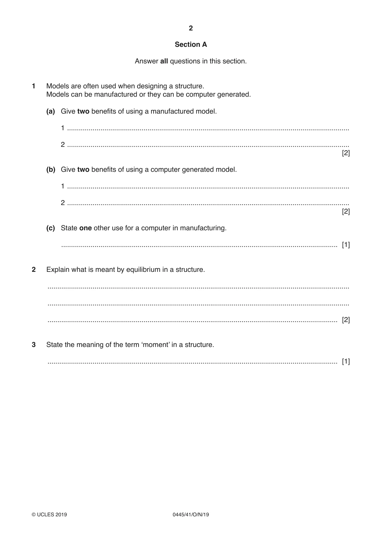
1 Models are often used when designing a structure. Models can be manufactured or they can be computer generated. (a) Give two benefits of using a manufactured model. 1 ................................................................................................................................................ 2 ................................................................................................................................................ [2] (b) Give two benefits of using a computer generated model. 1 ................................................................................................................................................ 2 ................................................................................................................................................ [2] (c) State one other use for a computer in manufacturing. ............................................................................................................................................. [1]
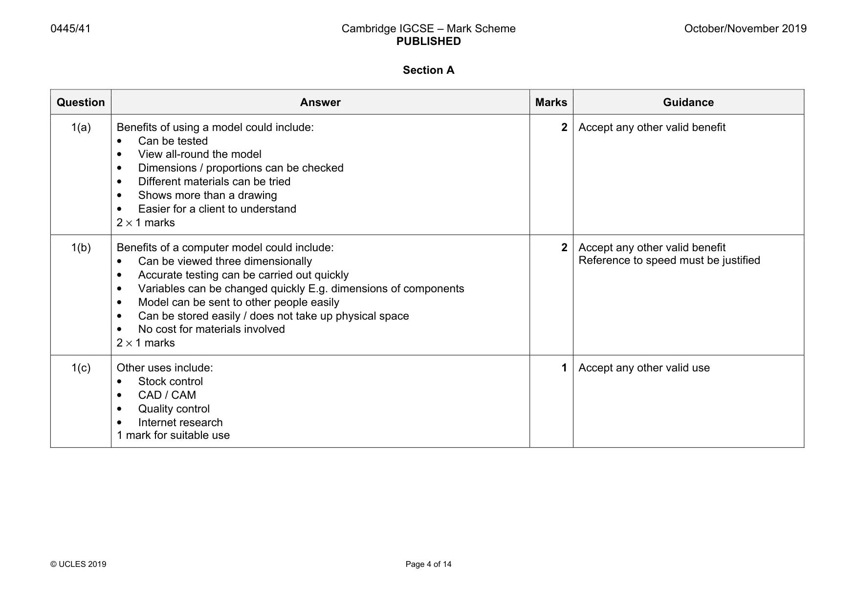
Mark scheme: 1(a) Benefits of using a model could include: • Can be tested • View all-round the model • Dimensions / proportions can be checked • Different materials can be tried • Shows more than a drawing • Easier for a client to understand 2 × 1 marks 2 Accept any other valid benefit 1(b) Benefits of a computer model could include: • Can be viewed three dimensionally • Accurate testing can be carried out quickly • Variables can be changed quickly E.g. dimensions of components • Model can be sent to other people easily • Can be stored easily / does not take up physical space • No cost for materials involved 2 × 1 marks 2 Accept any other valid benefit Reference to speed must be justified 1(c) Other uses include: • Stock control • CAD / CAM • Quality control • Internet research 1 mark for suitable use 1 Accept any other valid use
Q2 · Explain what is meant by equilibrium in a structure
2 Explain what is meant by equilibrium in a structure. .......................................................................................................................................................... .......................................................................................................................................................... .................................................................................................................................................... [2]
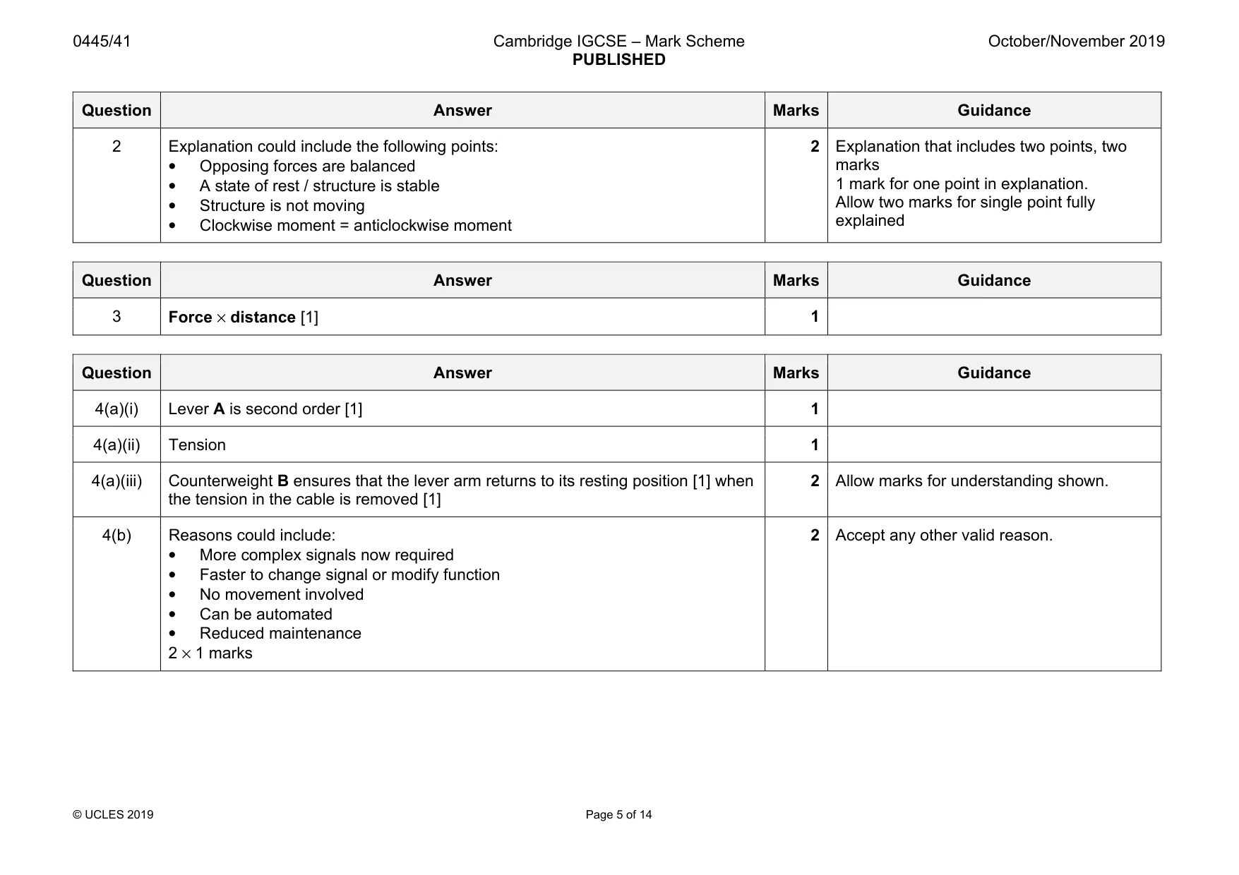
Mark scheme: 2 Explanation could include the following points: • Opposing forces are balanced • A state of rest / structure is stable • Structure is not moving • Clockwise moment = anticlockwise moment 2 Explanation that includes two points, two marks 1 mark for one point in explanation. Allow two marks for single point fully explained
Q3 · State the meaning of the term ‘moment’ in a structure
3 State the meaning of the term ‘moment’ in a structure. .................................................................................................................................................... [1]
Mark scheme: 3 1
Q4 · A mechanism used to manually operate a railway signal
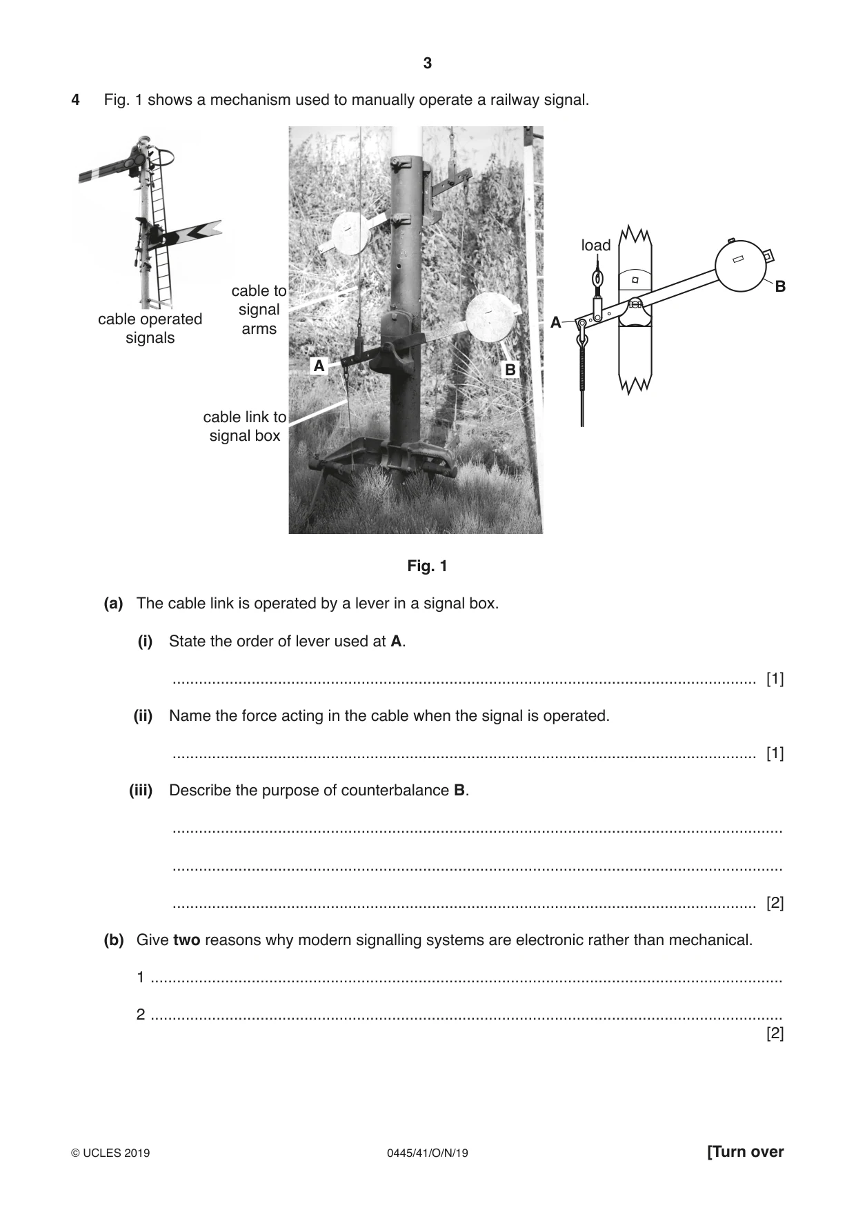
4 Fig. 1 shows a mechanism used to manually operate a railway signal. load cable to B signal cable operated A arms signals A B cable link to signal box Fig. 1 (a) The cable link is operated by a lever in a signal box. (i) State the order of lever used at A. ..................................................................................................................................... [1] (ii) Name the force acting in the cable when the signal is operated. ..................................................................................................................................... [1] (iii) Describe the purpose of counterbalance B. ........................................................................................................................................... ........................................................................................................................................... ..................................................................................................................................... [2] (b) Give two reasons why modern signalling systems are electronic rather than mechanical. 1 ................................................................................................................................................ 2 ................................................................................................................................................ [2]
Mark scheme: 4(a)(i) Lever A is second order [1] 1 4(a)(ii) Tension 1 4(a)(iii) Counterweight B ensures that the lever arm returns to its resting position [1] when the tension in the cable is removed [1] 2 Allow marks for understanding shown. 4(b) Reasons could include: • More complex signals now required • Faster to change signal or modify function • No movement involved • Can be automated • Reduced maintenance 2 × 1 marks 2 Accept any other valid reason.
Q5 · Two eccentrics on a locomotive axle
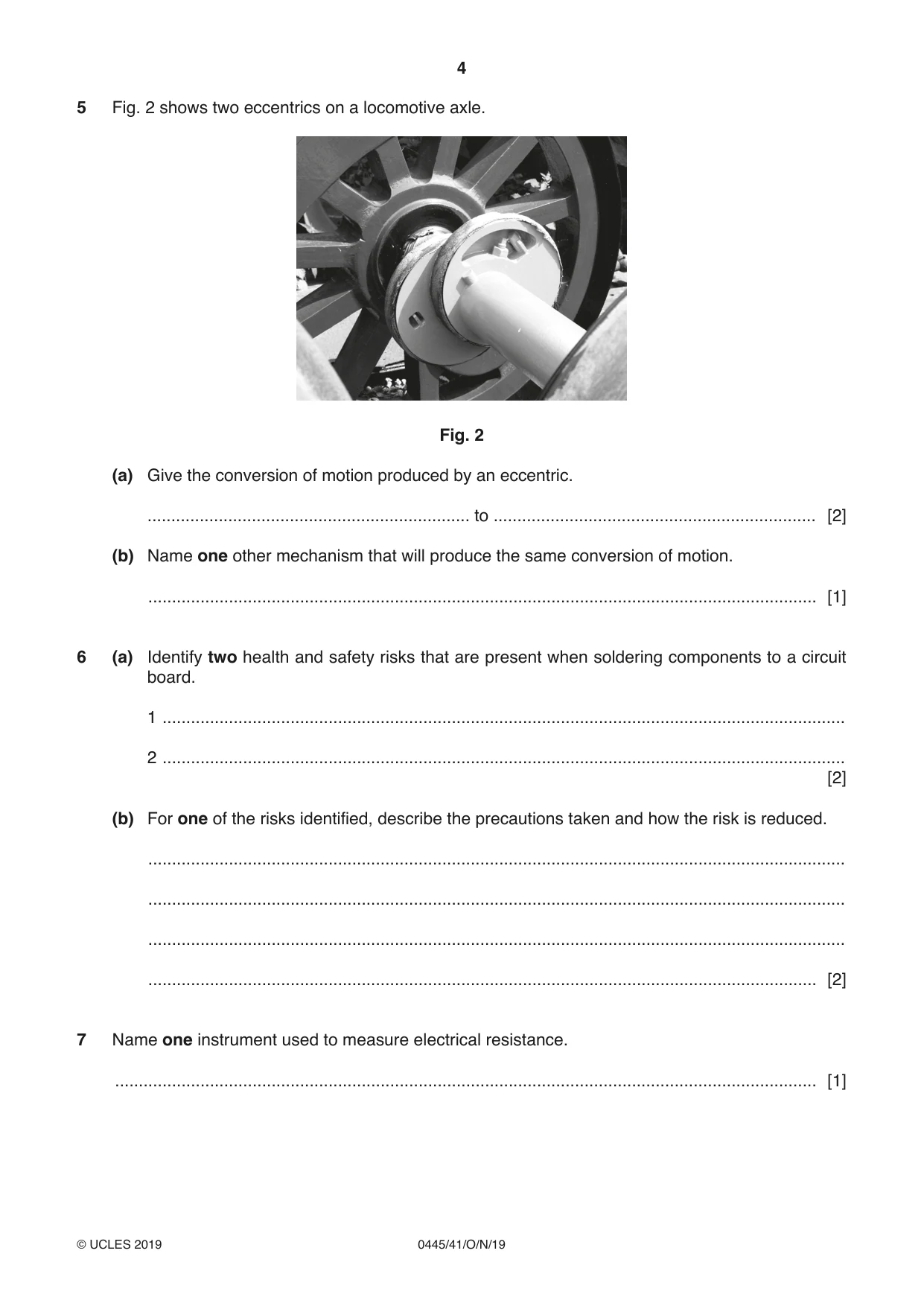
5 Fig. 2 shows two eccentrics on a locomotive axle. Fig. 2 (a) Give the conversion of motion produced by an eccentric. .................................................................... to .................................................................... [2] (b) Name one other mechanism that will produce the same conversion of motion. ............................................................................................................................................. [1]
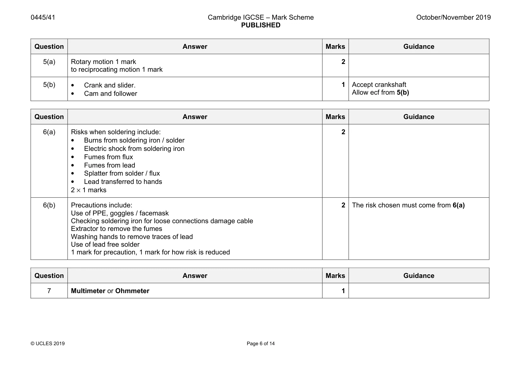
Mark scheme: 5(a) Rotary motion 1 mark to reciprocating motion 1 mark 2 5(b) • Crank and slider. • Cam and follower 1 Accept crankshaft Allow ecf from 5(b)
Q6 · Identify two health and safety risks that are present when soldering components to a…
6 (a) Identify two health and safety risks that are present when soldering components to a circuit board. 1 ................................................................................................................................................ 2 ................................................................................................................................................ [2] (b) For one of the risks identified, describe the precautions taken and how the risk is reduced. ................................................................................................................................................... ................................................................................................................................................... ................................................................................................................................................... ............................................................................................................................................. [2]
Mark scheme: 6(a) Risks when soldering include: • Burns from soldering iron / solder • Electric shock from soldering iron • Fumes from flux • Fumes from lead • Splatter from solder / flux • Lead transferred to hands 2 × 1 marks 2 6(b) Precautions include: Use of PPE, goggles / facemask Checking soldering iron for loose connections damage cable Extractor to remove the fumes Washing hands to remove traces of lead Use of lead free solder 1 mark for precaution, 1 mark for how risk is reduced 2 The risk chosen must come from 6(a)
Q7 · Name one instrument used to measure electrical resistance
7 Name one instrument used to measure electrical resistance. .................................................................................................................................................... [1]
Mark scheme: 7 Multimeter or Ohmmeter 1
Q8 · Explain what is meant by tolerance in a fixed resistor
8 (a) Explain what is meant by tolerance in a fixed resistor. ................................................................................................................................................... ................................................................................................................................................... ............................................................................................................................................. [2] (b) State how the tolerance is shown on a fixed resistor. ............................................................................................................................................. [1]
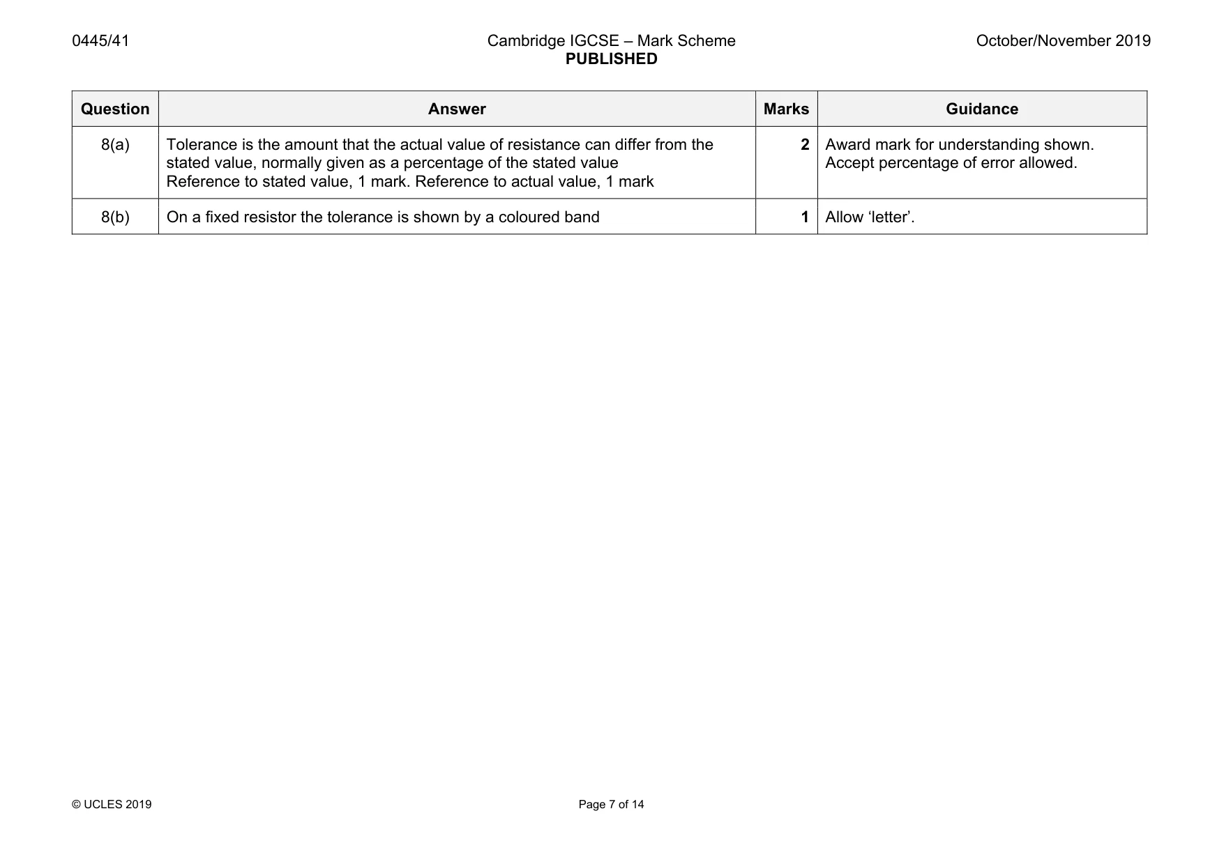
Mark scheme: 8(a) Tolerance is the amount that the actual value of resistance can differ from the stated value, normally given as a percentage of the stated value Reference to stated value, 1 mark. Reference to actual value, 1 mark 2 Award mark for understanding shown. Accept percentage of error allowed. 8(b) On a fixed resistor the tolerance is shown by a coloured band 1 Allow ‘letter’. Section B
Q9 · Scaffolding on the outside of a building
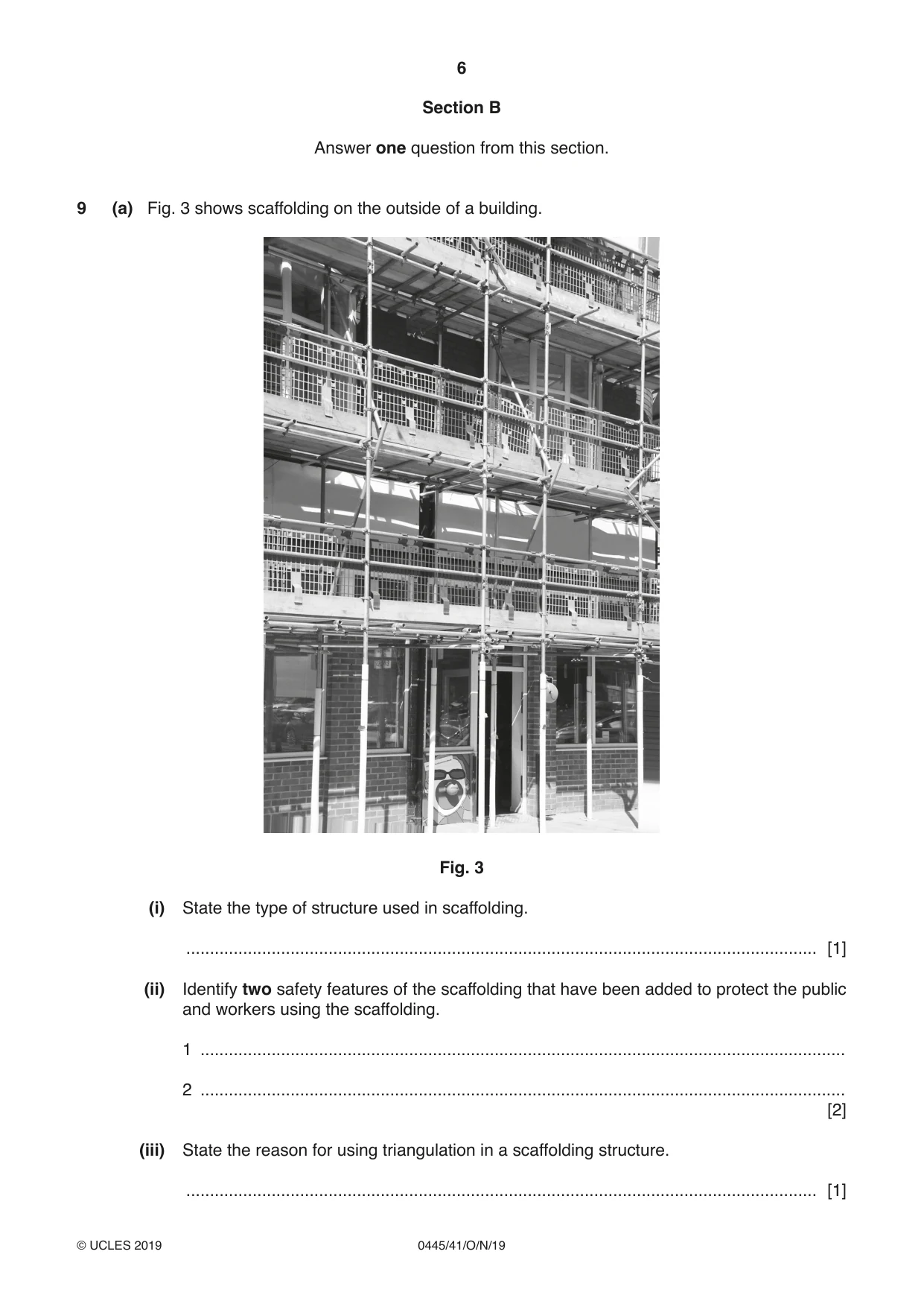
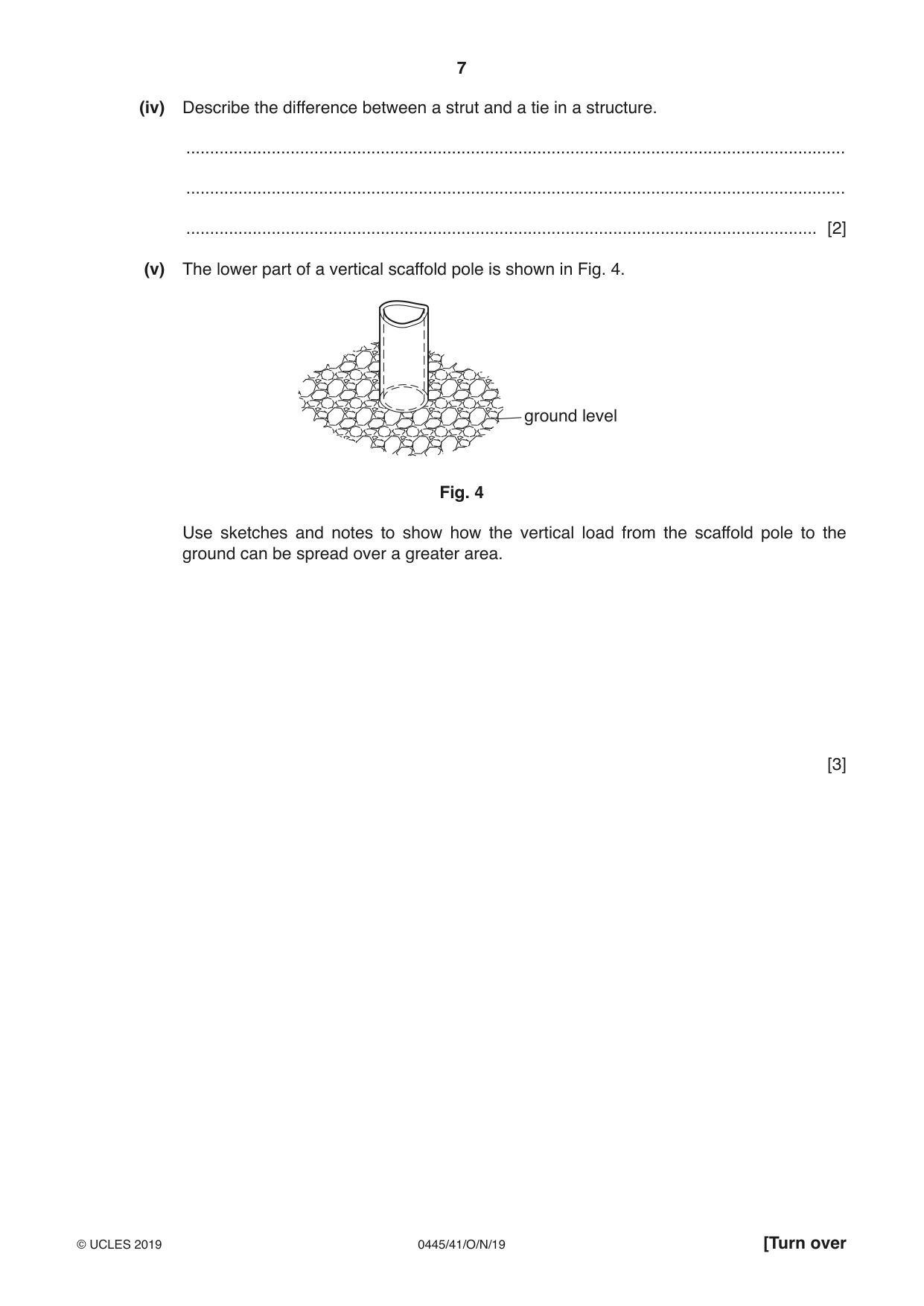
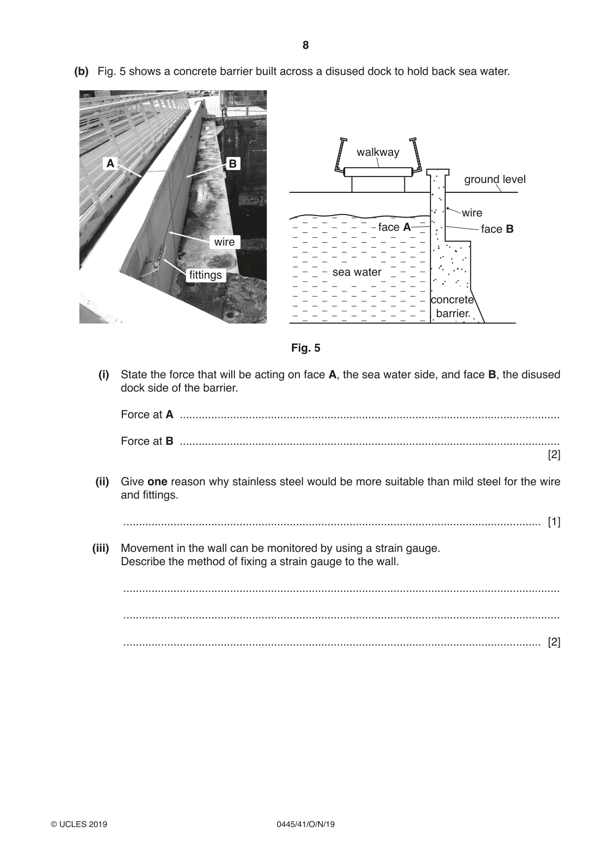
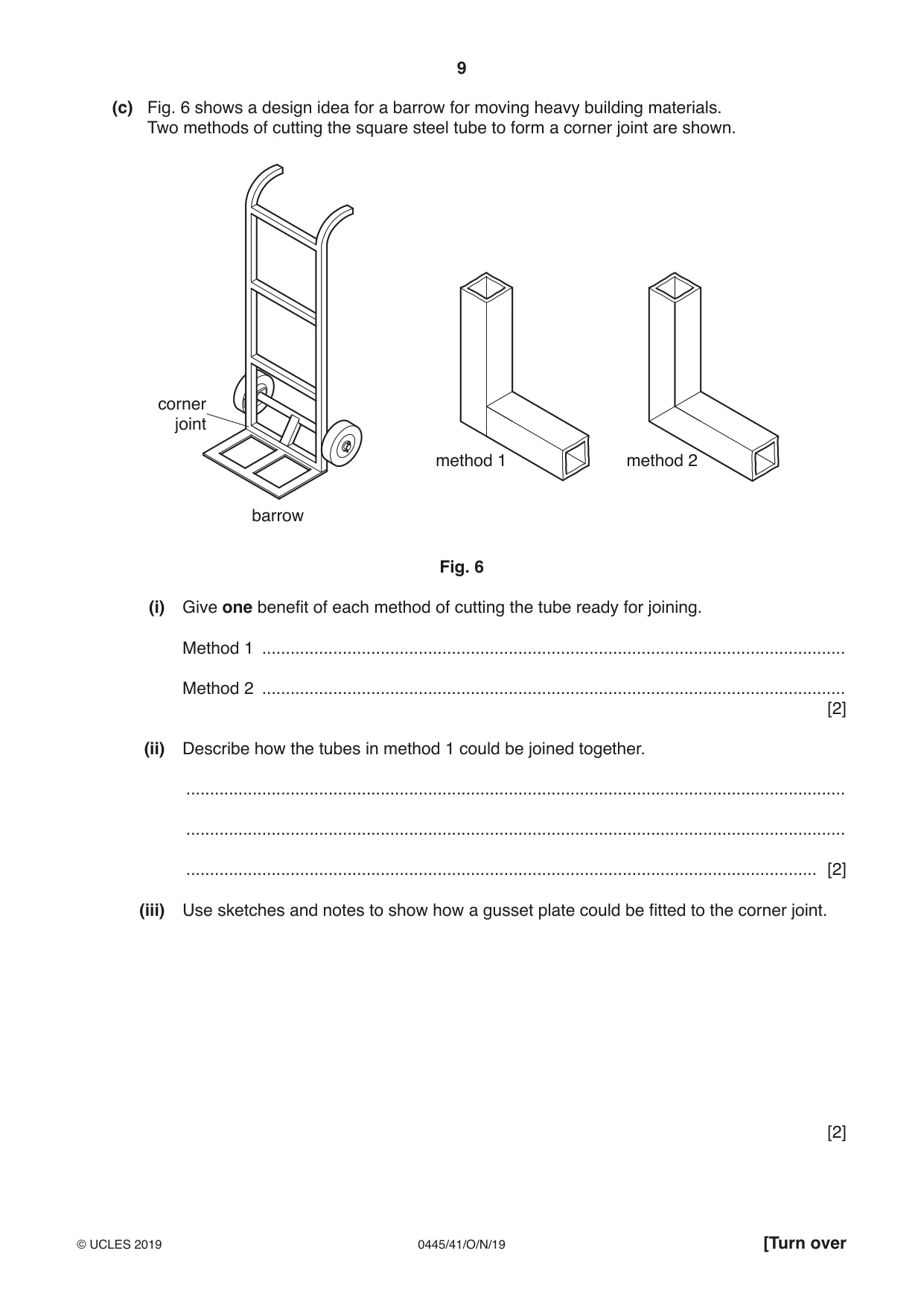
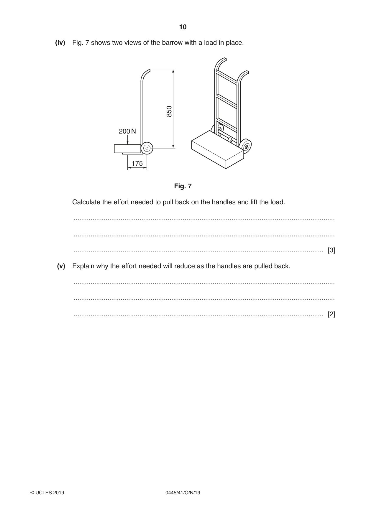
9 (a) Fig. 3 shows scaffolding on the outside of a building. Fig. 3 (i) State the type of structure used in scaffolding. ..................................................................................................................................... [1] (ii) Identify two safety features of the scaffolding that have been added to protect the public and workers using the scaffolding. 1 ........................................................................................................................................ 2 ........................................................................................................................................ [2] (iii) State the reason for using triangulation in a scaffolding structure. ..................................................................................................................................... [1] (iv) Describe the difference between a strut and a tie in a structure. ........................................................................................................................................... ........................................................................................................................................... ..................................................................................................................................... [2] (v) The lower part of a vertical scaffold pole is shown in Fig. 4. ground level Fig. 4 Use sketches and notes to show how the vertical load from the scaffold pole to the ground can be spread over a greater area. [3] (b) Fig. 5 shows a concrete barrier built across a disused dock to hold back sea water. walkway A B ground level wire face A face B wire fittings sea water concrete barrier Fig. 5 (i) State the force that will be acting on face A, the sea water side, and face B, the disused dock side of the barrier. Force at A ......................................................................................................................... Force at B ......................................................................................................................... [2] (ii) Give one reason why stainless steel would be more suitable than mild steel for the wire and fittings. ..................................................................................................................................... [1] (iii) Movement in the wall can be monitored by using a strain gauge. Describe the method of fixing a strain gauge to the wall. ........................................................................................................................................... ........................................................................................................................................... ..................................................................................................................................... [2] (c) Fig. 6 shows a design idea for a barrow for moving heavy building materials. Two methods of cutting the square steel tube to form a corner joint are shown. corner joint method 1 method 2 barrow Fig. 6 (i) Give one benefit of each method of cutting the tube ready for joining. Method 1 ........................................................................................................................... Method 2 ........................................................................................................................... [2] (ii) Describe how the tubes in method 1 could be joined together. ........................................................................................................................................... ........................................................................................................................................... ..................................................................................................................................... [2] (iii) Use sketches and notes to show how a gusset plate could be fitted to the corner joint. [2] (iv) Fig. 7 shows two views of the barrow with a load in place. 850 200 N 175 Fig. 7 Calculate the effort needed to pull back on the handles and lift the load. ........................................................................................................................................... ........................................................................................................................................... ..................................................................................................................................... [3] (v) Explain why the effort needed will reduce as the handles are pulled back. ........................................................................................................................................... ........................................................................................................................................... ..................................................................................................................................... [2]
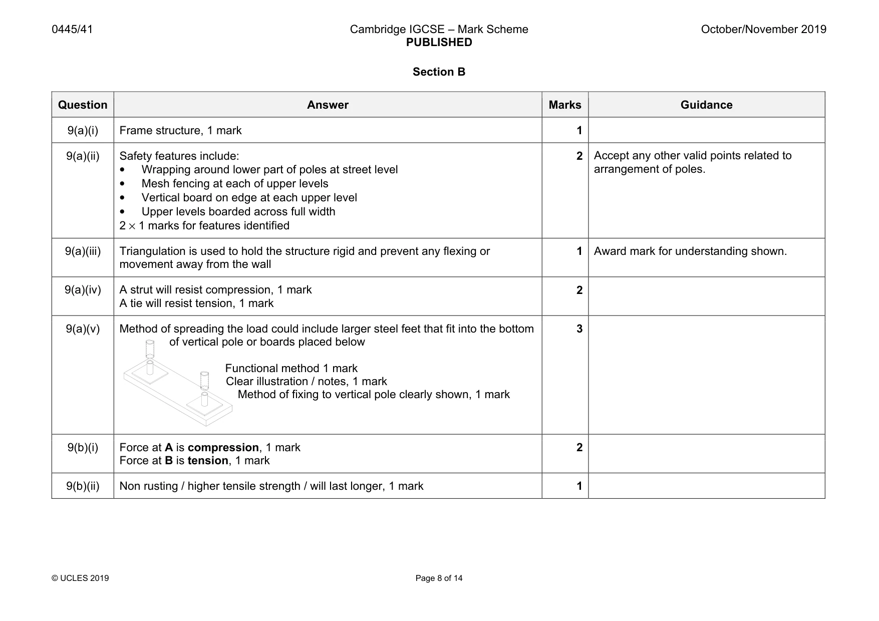
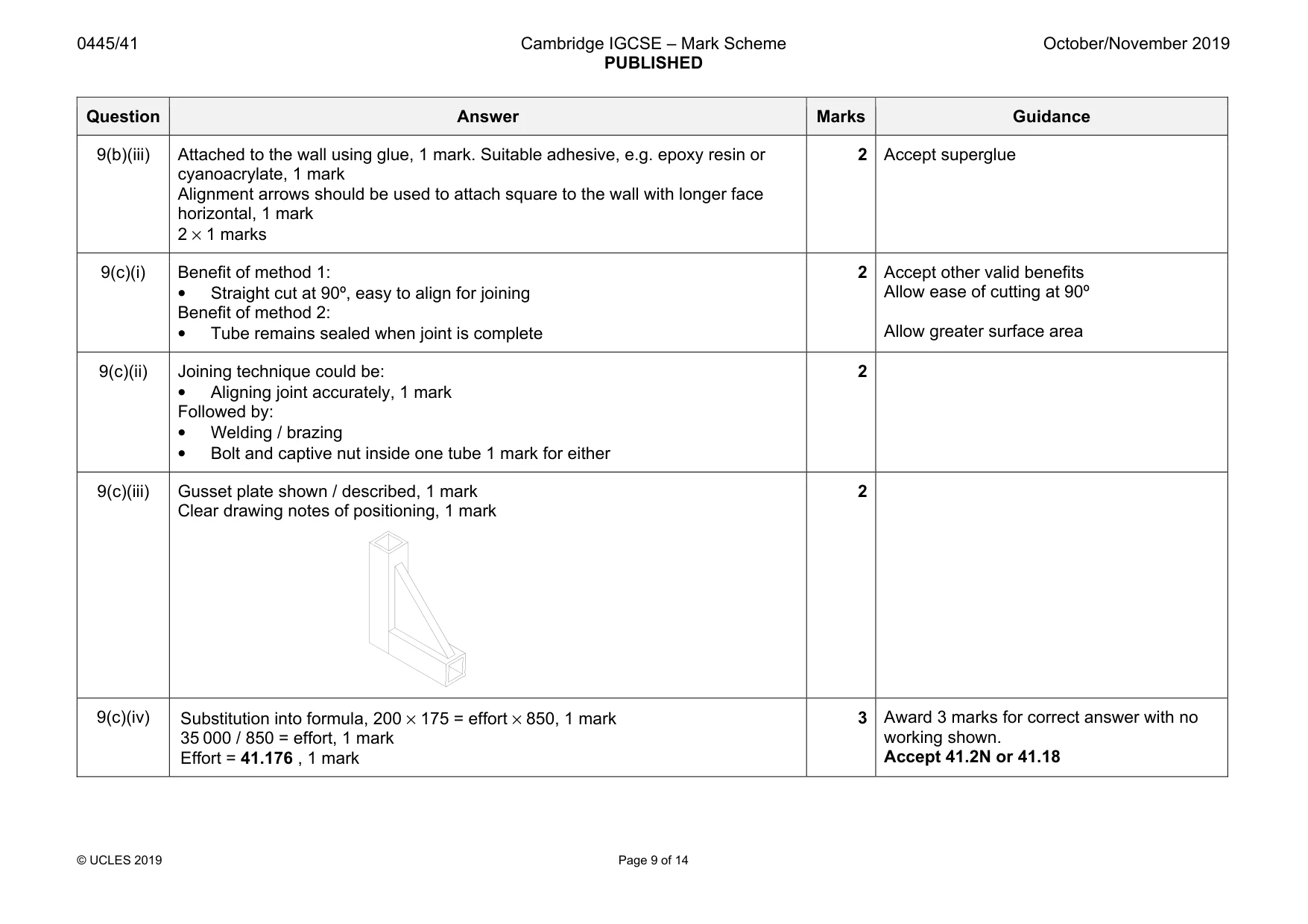
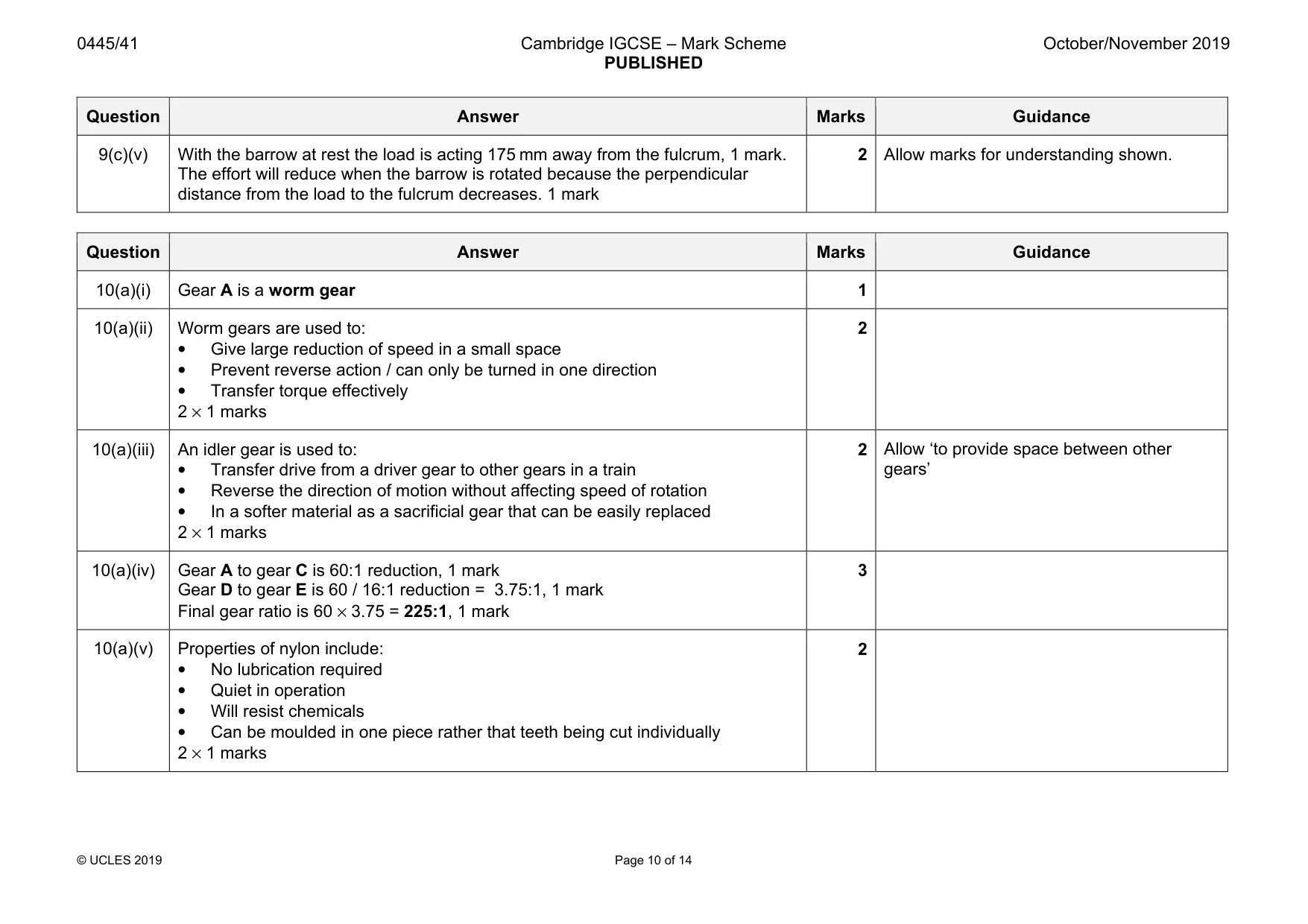
Mark scheme: 9(a)(i) Frame structure, 1 mark 1 9(a)(ii) Safety features include: • Wrapping around lower part of poles at street level • Mesh fencing at each of upper levels • Vertical board on edge at each upper level • Upper levels boarded across full width 2 × 1 marks for features identified 2 Accept any other valid points related to arrangement of poles. 9(a)(iii) Triangulation is used to hold the structure rigid and prevent any flexing or movement away from the wall 1 Award mark for understanding shown. 9(a)(iv) A strut will resist compression, 1 mark A tie will resist tension, 1 mark 2 9(a)(v) Method of spreading the load could include larger steel feet that fit into the bottom of vertical pole or boards placed below Functional method 1 mark Clear illustration / notes, 1 mark Method of fixing to vertical pole clearly shown, 1 mark 3 9(b)(i) Force at A is compression, 1 mark Force at B is tension, 1 mark 2 9(b)(ii) Non rusting / higher tensile strength / will last longer, 1 mark 1 Question Answer Marks Guidance 9(b)(iii) Attached to the wall using glue, 1 mark. Suitable adhesive, e.g. epoxy resin or cyanoacrylate, 1 mark Alignment arrows should be used to attach square to the wall with longer face horizontal, 1 mark 2 × 1 marks 2 Accept superglue 9(c)(i) Benefit of method 1: • Straight cut at 90º, easy to align for joining Benefit of method 2: • Tube remains sealed when joint is complete 2 Accept other valid benefits Allow ease of cutting at 90º Allow greater surface area 9(c)(ii) Joining technique could be: • Aligning joint accurately, 1 mark Followed by: • Welding / brazing • Bolt and captive nut inside one tube 1 mark for either 2 9(c)(iii) Gusset plate shown / described, 1 mark Clear drawing notes of positioning, 1 mark 2 9(c)(iv) Substitution into formula, 200 × 175 = effort × 850, 1 mark 35 000 / 850 = effort, 1 mark Effort = 41.176 , 1 mark 3 Award 3 marks for correct answer with no working shown. Accept 41.2N or 41.18 Question Answer Marks Guidance 9(c)(v) With the barrow at rest the load is acting 175 mm away from the fulcrum, 1 mark. The effort will reduce when the barrow is rotated because the perpendicular distance from the load to the fulcrum decreases. 1 mark 2 Allow marks for understanding shown.
Q10 · An arrangement of gears driven by a small electric motor
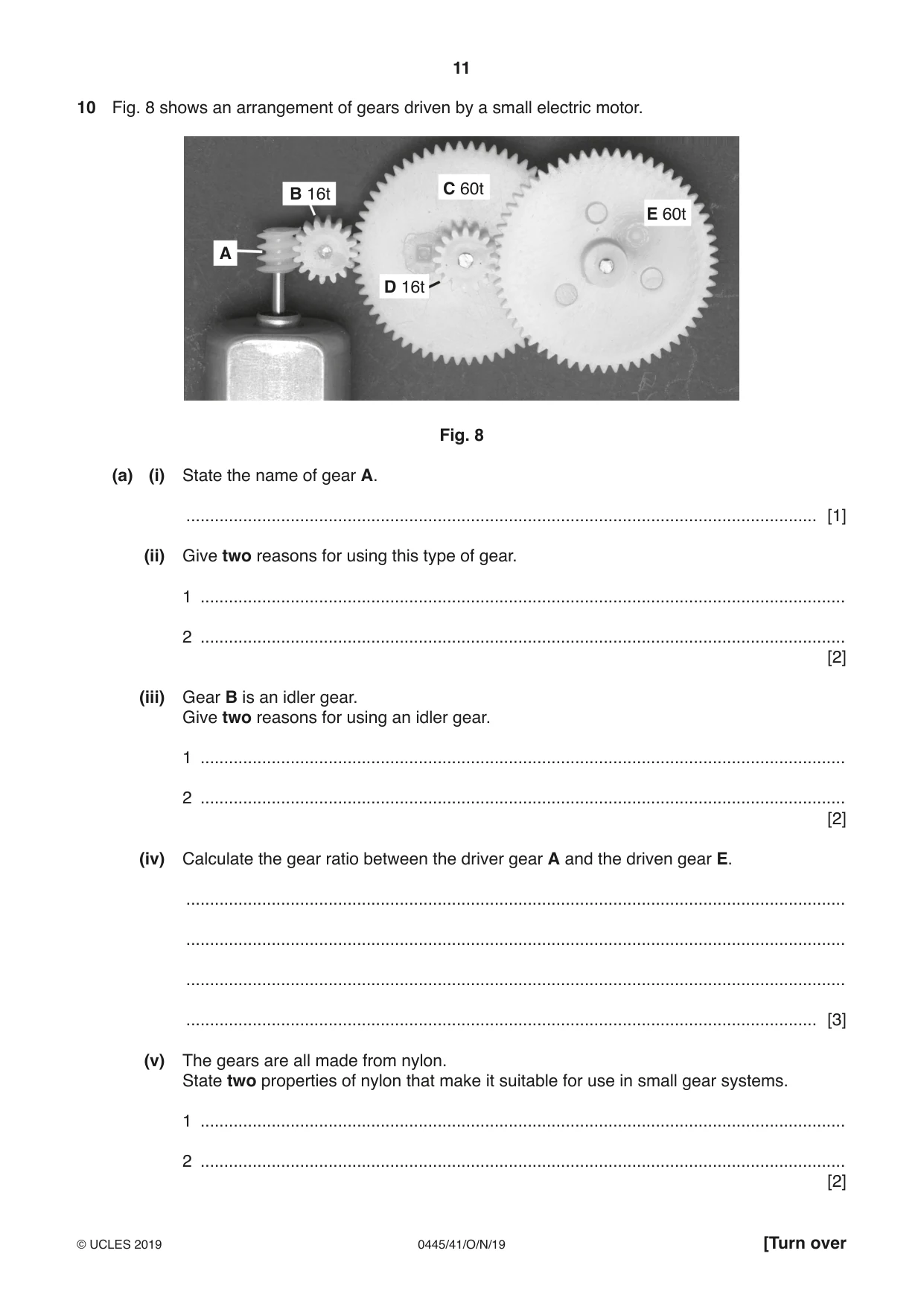
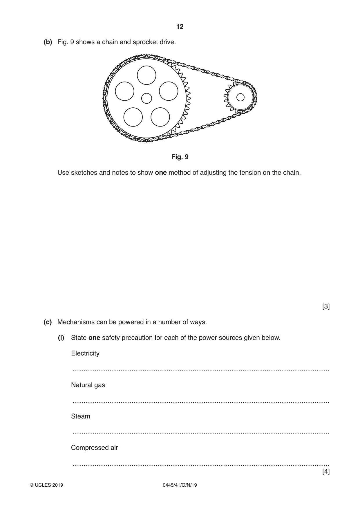
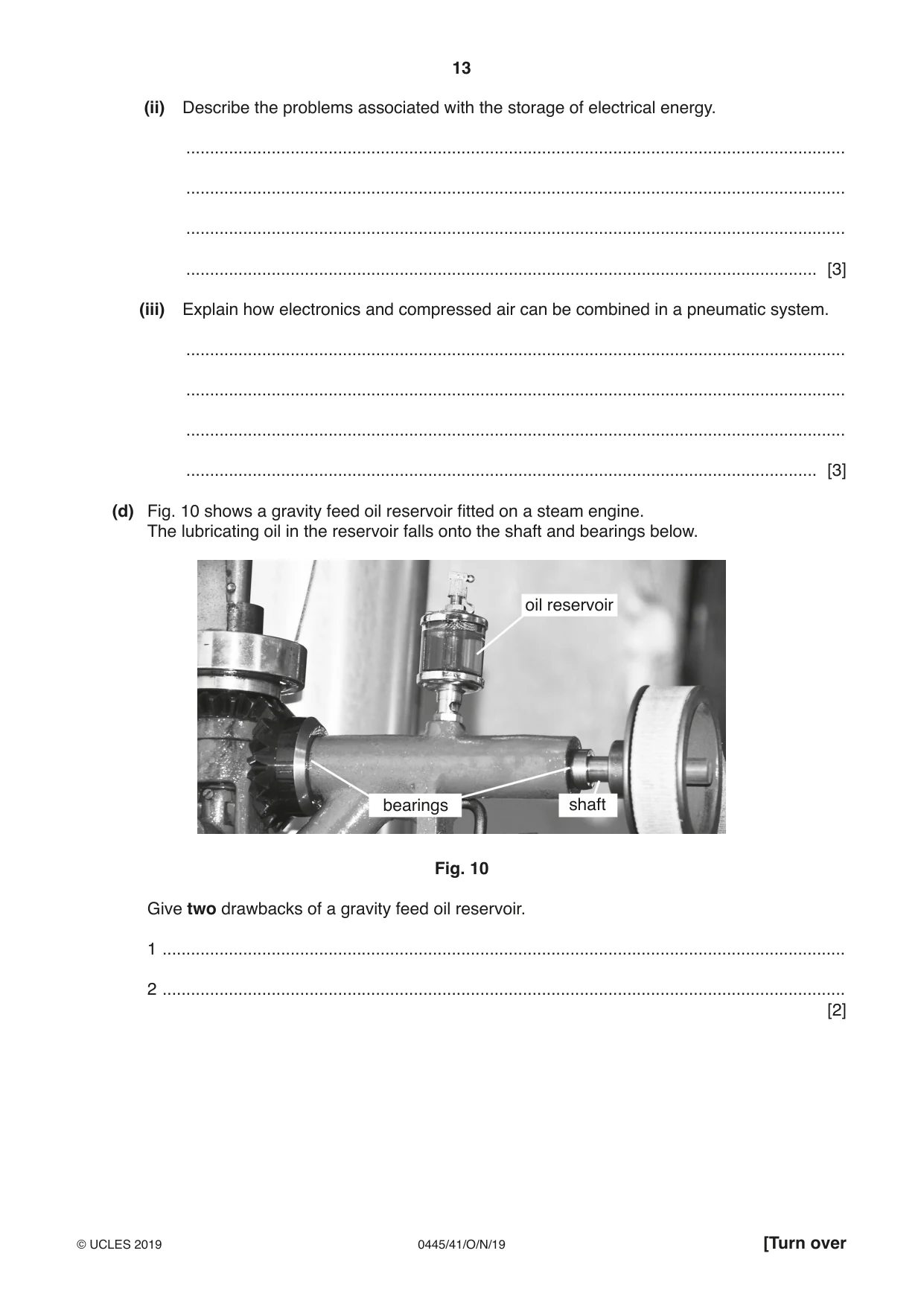
10 Fig. 8 shows an arrangement of gears driven by a small electric motor. C 60t B 16t E 60t A D 16t Fig. 8 (a) (i) State the name of gear A. ..................................................................................................................................... [1] (ii) Give two reasons for using this type of gear. 1 ........................................................................................................................................ 2 ........................................................................................................................................ [2] (iii) Gear B is an idler gear. Give two reasons for using an idler gear. 1 ........................................................................................................................................ 2 ........................................................................................................................................ [2] (iv) Calculate the gear ratio between the driver gear A and the driven gear E. ........................................................................................................................................... ........................................................................................................................................... ........................................................................................................................................... ..................................................................................................................................... [3] (v) The gears are all made from nylon. State two properties of nylon that make it suitable for use in small gear systems. 1 ........................................................................................................................................ 2 ........................................................................................................................................ [2] (b) Fig. 9 shows a chain and sprocket drive. Fig. 9 Use sketches and notes to show one method of adjusting the tension on the chain. [3] (c) Mechanisms can be powered in a number of ways. (i) State one safety precaution for each of the power sources given below. Electricity ........................................................................................................................................... Natural gas ........................................................................................................................................... Steam ........................................................................................................................................... Compressed air ........................................................................................................................................... [4] (ii) Describe the problems associated with the storage of electrical energy. ........................................................................................................................................... ........................................................................................................................................... ........................................................................................................................................... ..................................................................................................................................... [3] (iii) Explain how electronics and compressed air can be combined in a pneumatic system. ........................................................................................................................................... ........................................................................................................................................... ........................................................................................................................................... ..................................................................................................................................... [3] (d) Fig. 10 shows a gravity feed oil reservoir fitted on a steam engine. The lubricating oil in the reservoir falls onto the shaft and bearings below. oil reservoir bearings shaft Fig. 10 Give two drawbacks of a gravity feed oil reservoir. 1 ................................................................................................................................................ 2 ................................................................................................................................................ [2]
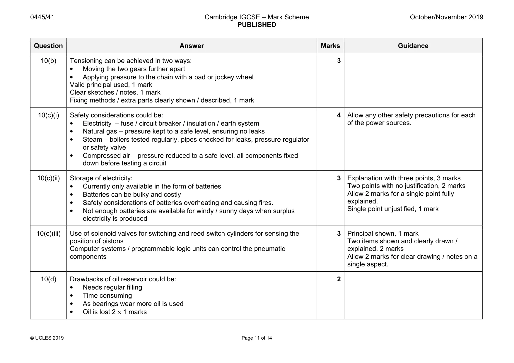
Mark scheme: 10(a)(i) Gear A is a worm gear 1 10(a)(ii) Worm gears are used to: • Give large reduction of speed in a small space • Prevent reverse action / can only be turned in one direction • Transfer torque effectively 2 × 1 marks 2 10(a)(iii) An idler gear is used to: • Transfer drive from a driver gear to other gears in a train • Reverse the direction of motion without affecting speed of rotation • In a softer material as a sacrificial gear that can be easily replaced 2 × 1 marks 2 Allow ‘to provide space between other gears’ 10(a)(iv) Gear A to gear C is 60:1 reduction, 1 mark Gear D to gear E is 60 / 16:1 reduction = 3.75:1, 1 mark Final gear ratio is 60 × 3.75 = 225:1, 1 mark 3 10(a)(v) Properties of nylon include: • No lubrication required • Quiet in operation • Will resist chemicals • Can be moulded in one piece rather that teeth being cut individually 2 × 1 marks 2 Question Answer Marks Guidance 10(b) Tensioning can be achieved in two ways: • Moving the two gears further apart • Applying pressure to the chain with a pad or jockey wheel Valid principal used, 1 mark Clear sketches / notes, 1 mark Fixing methods / extra parts clearly shown / described, 1 mark 3 10(c)(i) Safety considerations could be: • Electricity – fuse / circuit breaker / insulation / earth system • Natural gas – pressure kept to a safe level, ensuring no leaks • Steam – boilers tested regularly, pipes checked for leaks, pressure regulator or safety valve • Compressed air – pressure reduced to a safe level, all components fixed down before testing a circuit 4 Allow any other safety precautions for each of the power sources. 10(c)(ii) Storage of electricity: • Currently only available in the form of batteries • Batteries can be bulky and costly • Safety considerations of batteries overheating and causing fires. • Not enough batteries are available for windy / sunny days when surplus electricity is produced 3 Explanation with three points, 3 marks Two points with no justification, 2 marks Allow 2 marks for a single point fully explained. Single point unjustified, 1 mark 10(c)(iii) Use of solenoid valves for switching and reed switch cylinders for sensing the position of pistons Computer systems / programmable logic units can control the pneumatic components 3 Principal shown, 1 mark Two items shown and clearly drawn / explained, 2 marks Allow 2 marks for clear drawing / notes on a single aspect. 10(d) Drawbacks of oil reservoir could be: • Needs regular filling • Time consuming • As bearings wear more oil is used • Oil is lost 2 × 1 marks 2
Q11 · Equipment used during the soldering process
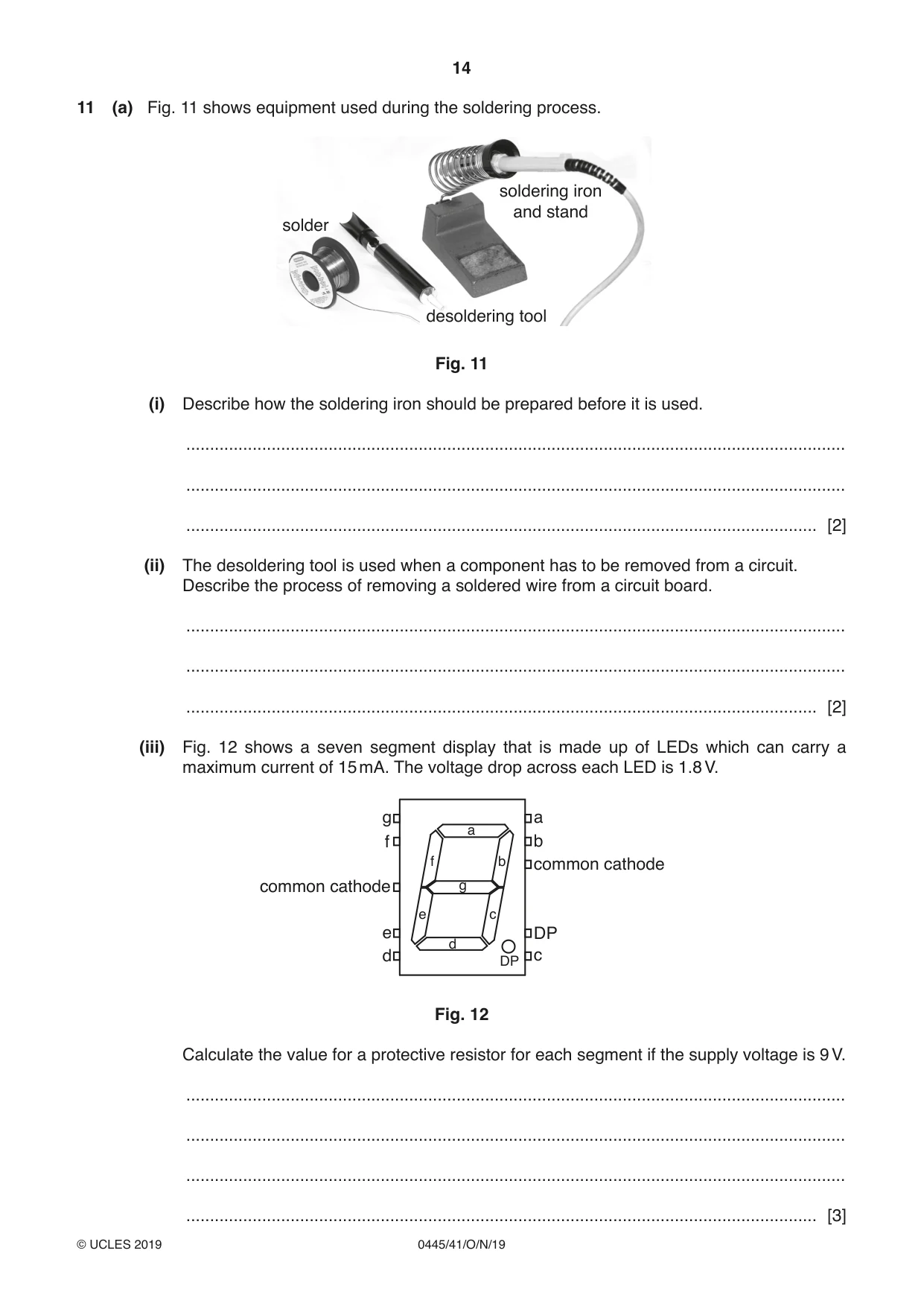
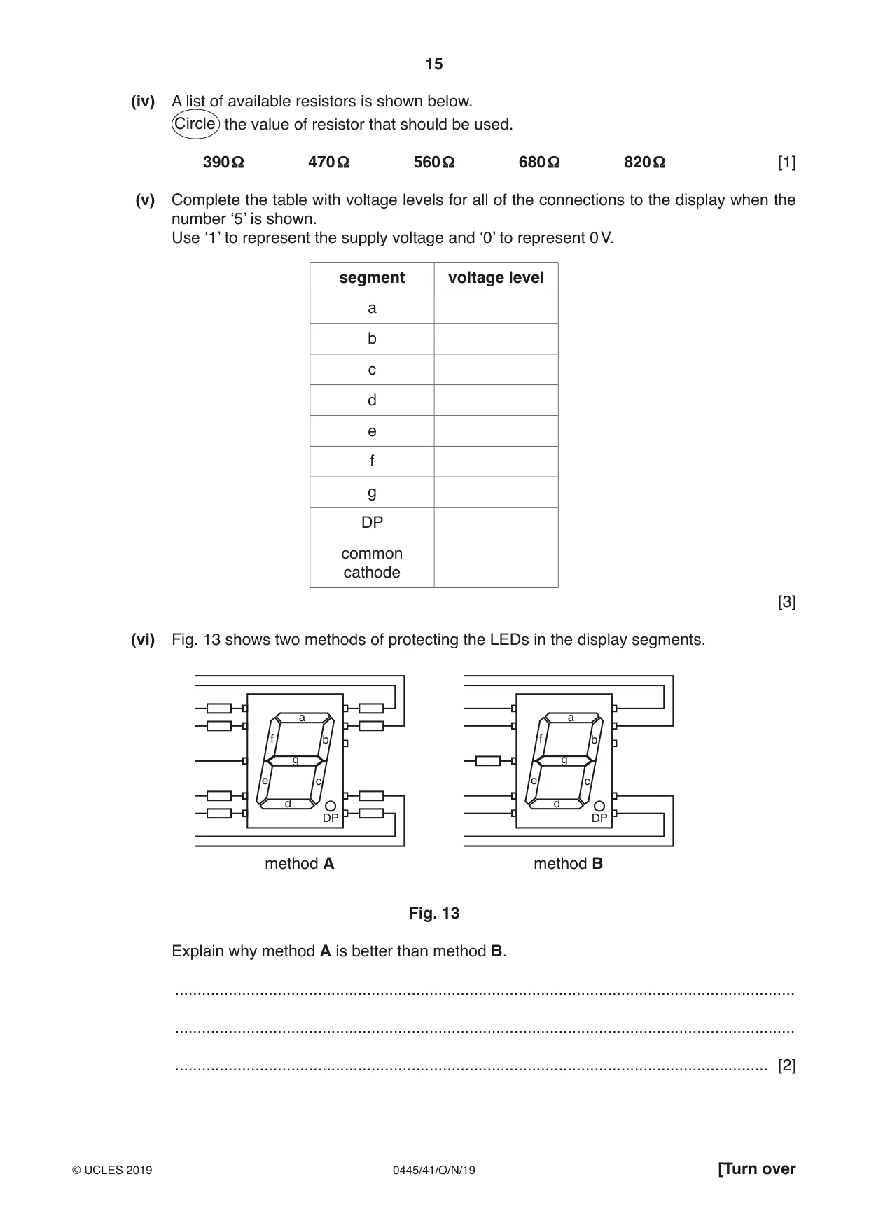
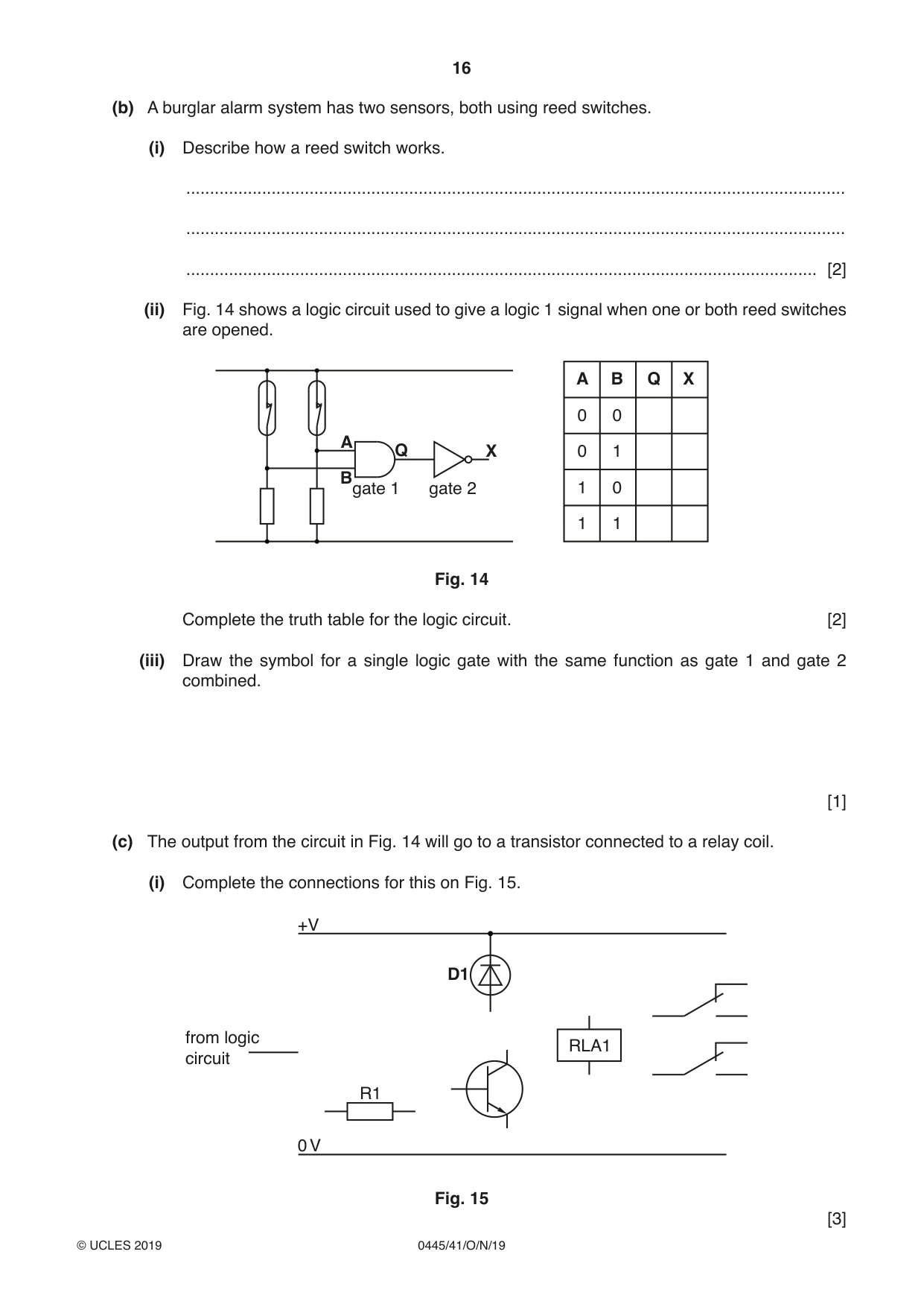
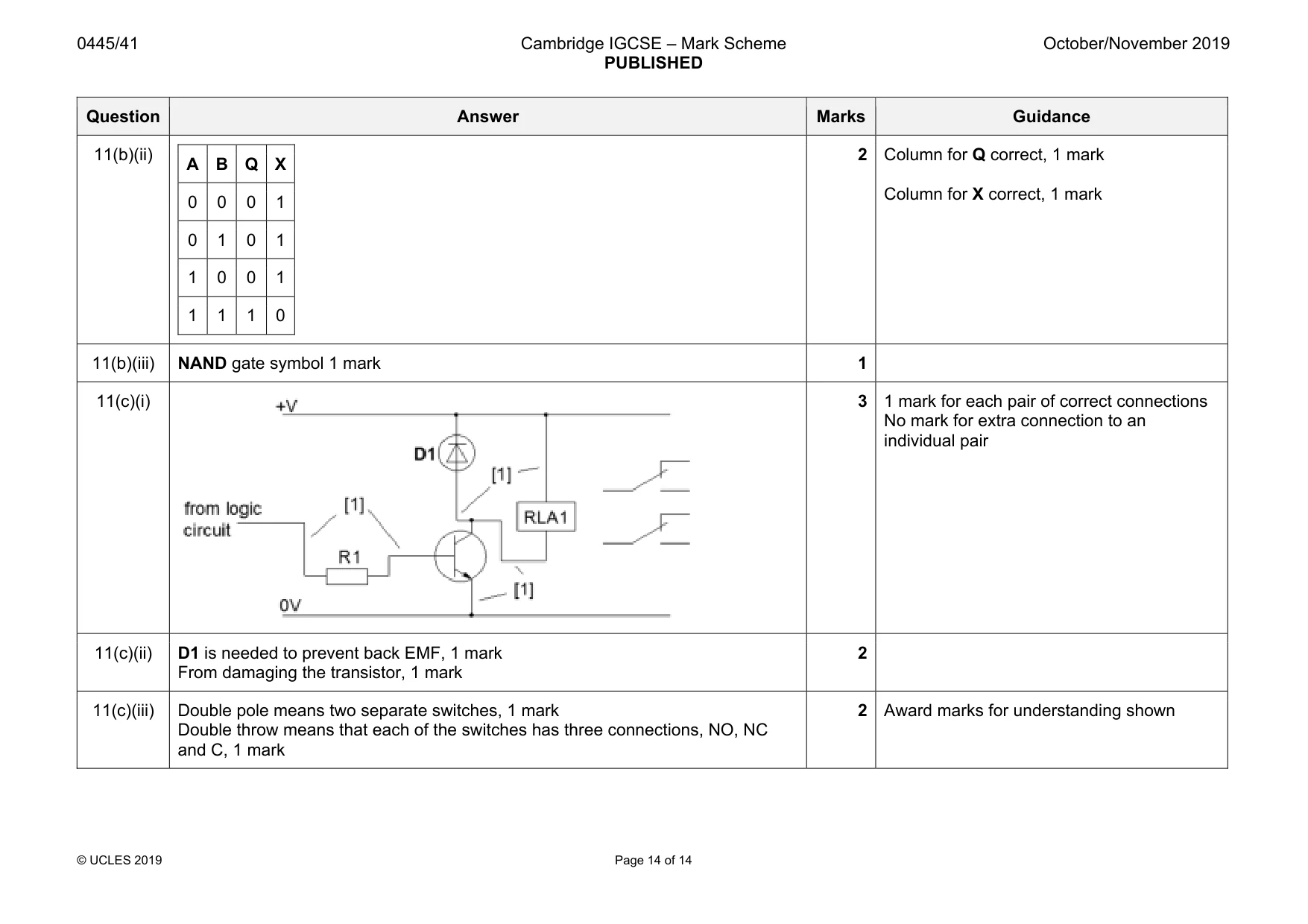
11 (a) Fig. 11 shows equipment used during the soldering process. soldering iron and stand solder desoldering tool Fig. 11 (i) Describe how the soldering iron should be prepared before it is used. ........................................................................................................................................... ........................................................................................................................................... ..................................................................................................................................... [2] (ii) The desoldering tool is used when a component has to be removed from a circuit. Describe the process of removing a soldered wire from a circuit board. ........................................................................................................................................... ........................................................................................................................................... ..................................................................................................................................... [2] (iii) Fig. 12 shows a seven segment display that is made up of LEDs which can carry a maximum current of 15 mA. The voltage drop across each LED is 1.8 V. g a a f b f b common cathode common cathode g e c e DP d d DP c Fig. 12 Calculate the value for a protective resistor for each segment if the supply voltage is 9 V. ........................................................................................................................................... ........................................................................................................................................... ........................................................................................................................................... ..................................................................................................................................... [3] (iv) A list of available resistors is shown below. Circle the value of resistor that should be used. 390 Ω 470 Ω 560 Ω 680 Ω 820 Ω [1] (v) Complete the table with voltage levels for all of the connections to the display when the number ‘5’ is shown. Use ‘1’ to represent the supply voltage and ‘0’ to represent 0 V. segment voltage level a b c d e f g DP common cathode [3] (vi) Fig. 13 shows two methods of protecting the LEDs in the display segments. a a f b f b g g e c e c d d DP DP method A method B Fig. 13 Explain why method A is better than method B. ........................................................................................................................................... ........................................................................................................................................... ..................................................................................................................................... [2] (b) A burglar alarm system has two sensors, both using reed switches. (i) Describe how a reed switch works. ........................................................................................................................................... ........................................................................................................................................... ..................................................................................................................................... [2] (ii) Fig. 14 shows a logic circuit used to give a logic 1 signal when one or both reed switches are opened. A B Q X 0 0 A Q X 0 1 B gate 1 gate 2 1 0 1 1 Fig. 14 Complete the truth table for the logic circuit. [2] (iii) Draw the symbol for a single logic gate with the same function as gate 1 and gate 2 combined. [1] (c) The output from the circuit in Fig. 14 will go to a transistor connected to a relay coil. (i) Complete the connections for this on Fig. 15. +V D1 from logic RLA1 circuit R1 0 V Fig. 15
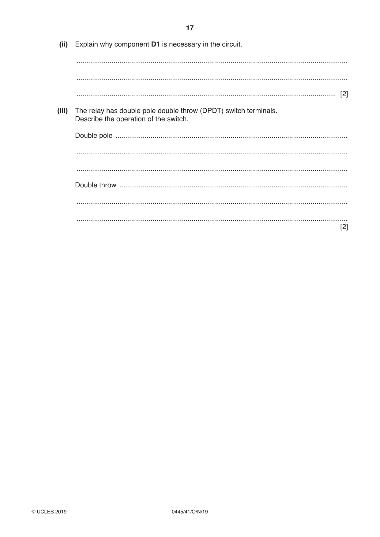
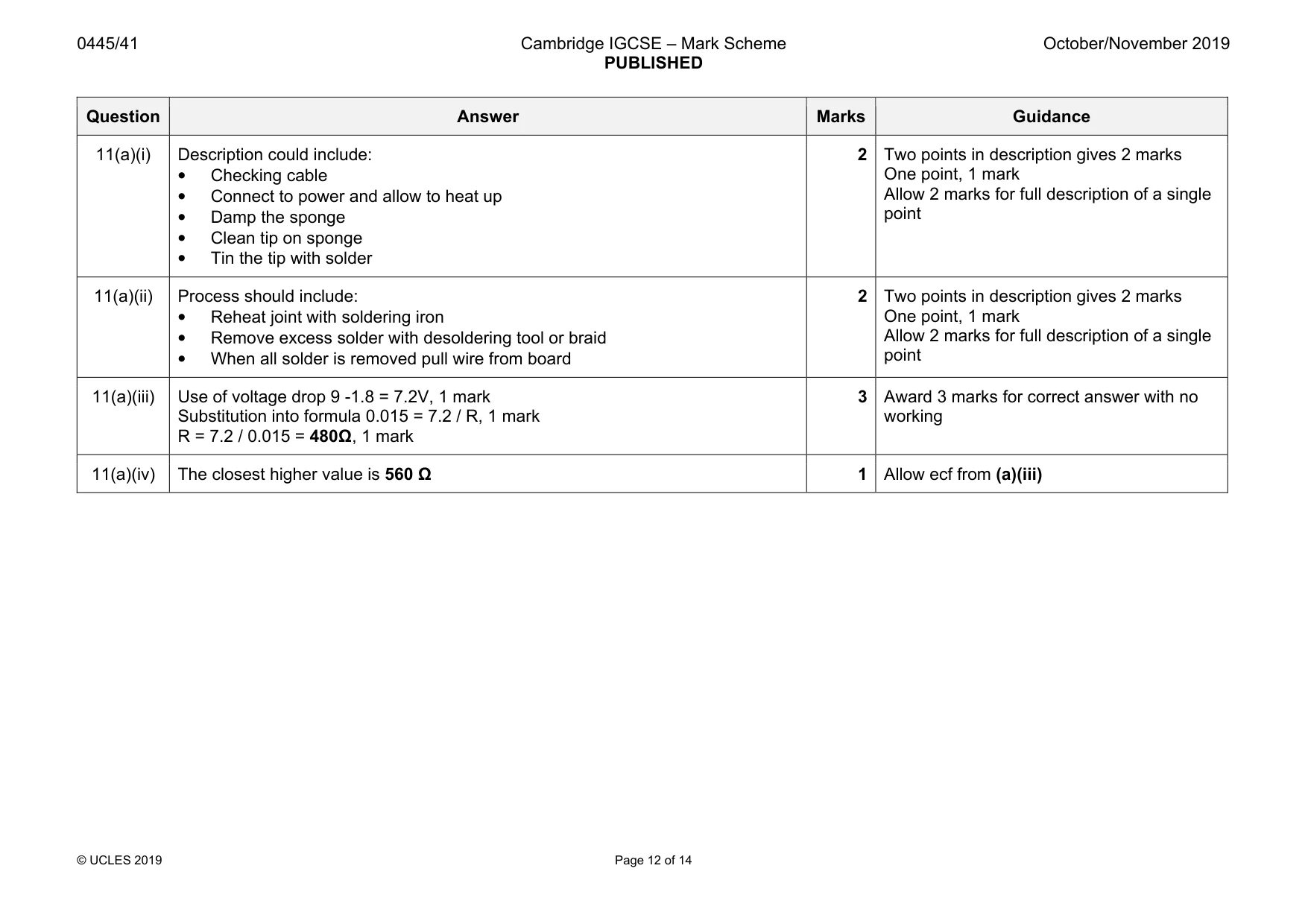
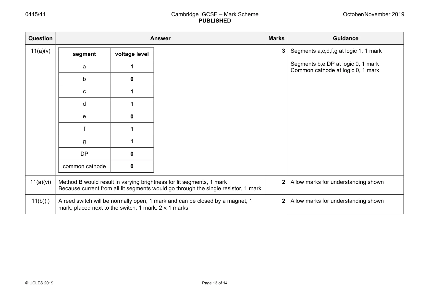
Mark scheme: 11(a)(i) Description could include: • Checking cable • Connect to power and allow to heat up • Damp the sponge • Clean tip on sponge • Tin the tip with solder 2 One point, 1 mark Allow 2 marks for full description of a single point 11(a)(ii) Process should include: • Reheat joint with soldering iron • Remove excess solder with desoldering tool or braid • When all solder is removed pull wire from board 2 Two points in description gives 2 marks One point, 1 mark Allow 2 marks for full description of a single point 11(a)(iii) Use of voltage drop 9 -1.8 = 7.2V, 1 mark Substitution into formula 0.015 = 7.2 / R, 1 mark R = 7.2 / 0.015 = 480Ω, 1 mark 3 Award 3 marks for correct answer with no working 11(a)(iv) The closest higher value is 560 Ω 1 Allow ecf from (a)(iii) Question Answer Marks Guidance 11(a)(v) segment voltage level a 1 b 0 c 1 d 1 e 0 f 1 g 1 DP 0 common cathode 0 3 Segments a,c,d,f,g at logic 1, 1 mark Segments b,e,DP at logic 0, 1 mark Common cathode at logic 0, 1 mark 11(a)(vi) Method B would result in varying brightness for lit segments, 1 mark Because current from all lit segments would go through the single resistor, 1 mark 2 Allow marks for understanding shown 11(b)(i) A reed switch will be normally open, 1 mark and can be closed by a magnet, 1 mark, placed next to the switch, 1 mark. 2 × 1 marks 2 Allow marks for understanding shown Question Answer Marks Guidance 11(b)(ii) A B Q X 0 0 0 1 0 1 0 1 1 0 0 1 1 1 1 0 2 Column for Q correct, 1 mark Column for X correct, 1 mark 11(b)(iii) NAND gate symbol 1 mark 1 11(c)(i) 3 1 mark for each pair of correct connections No mark for extra connection to an individual pair 11(c)(ii) D1 is needed to prevent back EMF, 1 mark From damaging the transistor, 1 mark 2 11(c)(iii) Double pole means two separate switches, 1 mark Double throw means that each of the switches has three connections, NO, NC and C, 1 mark 2 Award marks for understanding shown
What was in this paper
The subtopics covered by these 11 questions, and how many questions each got. Open one in a new tab to see every Cambridge question on it.
What you needed in this session
Cambridge’s own grade thresholds for 2019 Oct/Nov, Paper 4 · Variant 1. A higher threshold means an easier paper — the bar moves with how the cohort did.