Cambridge IGCSE Design and Technology 0445 — 2018 Oct/Nov Paper 4 · Variant 1
0445/41/O/N/18 · 12 questions · 50 marks · ≈56 min
The question paper and its mark scheme, free to read here and free to download. This is Cambridge’s own paper, exactly as it was sat.
Question paper20 pages


Mark scheme13 pages
Answers below. Sit the paper first if you are practising.
Questions as text
Question 1
1 (a) Fig. 1 shows a computer keyboard. The keys marked X, Y and Z act as toggle switches. Y Z X Fig. 1 Describe the switching action of all of the other keys on the keyboard. ...............................................................................................................................................[1] (b) Give one different use of a toggle switch. ...............................................................................................................................................[1]
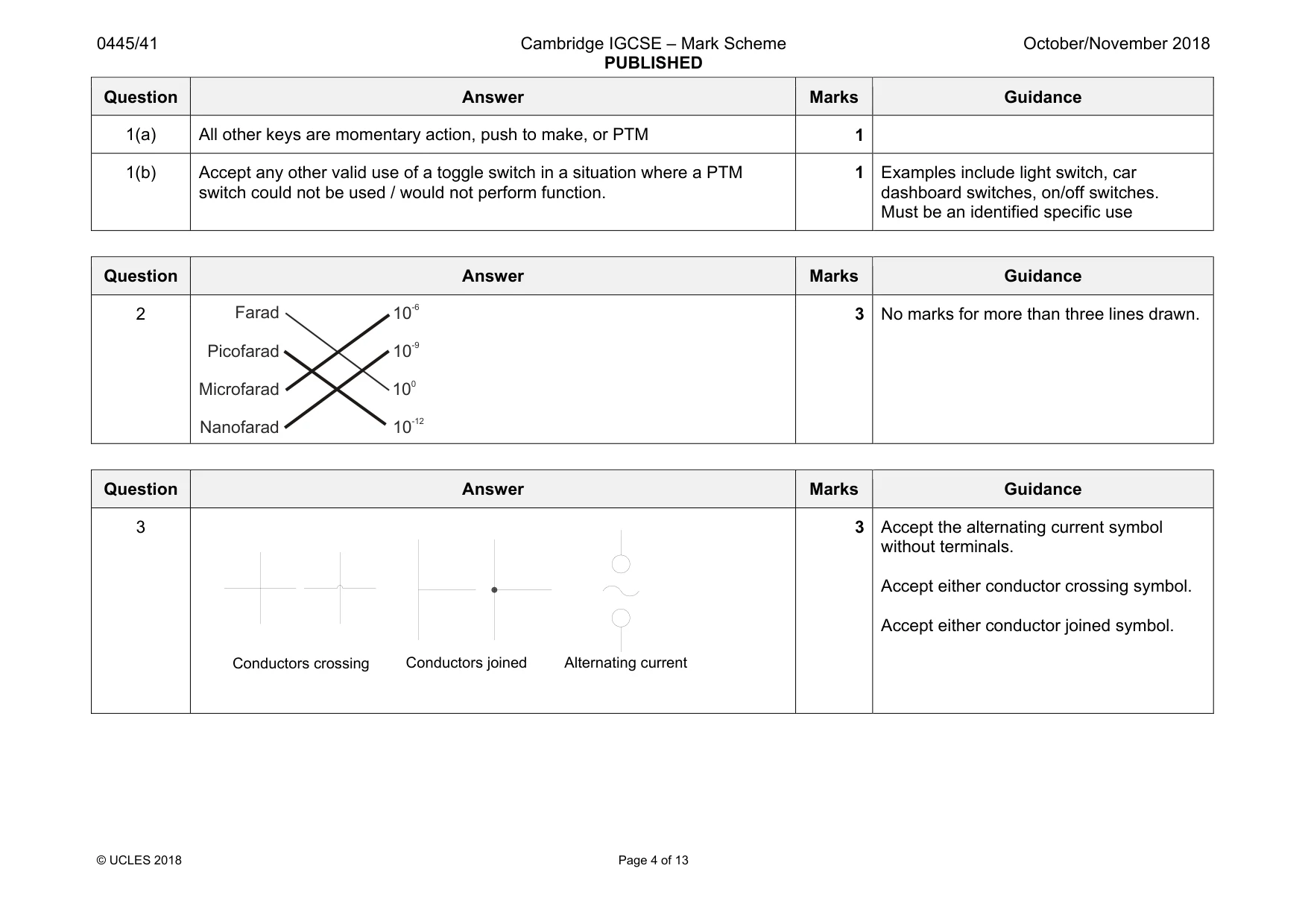
Mark scheme: 1(a) All other keys are momentary action, push to make, or PTM 1 1(b) Accept any other valid use of a toggle switch in a situation where a PTM switch could not be used / would not perform function. 1 Examples include light switch, car dashboard switches, on/off switches. Must be an identified specific use
Q2 · Capacitors are available in a range of sub-multiple values
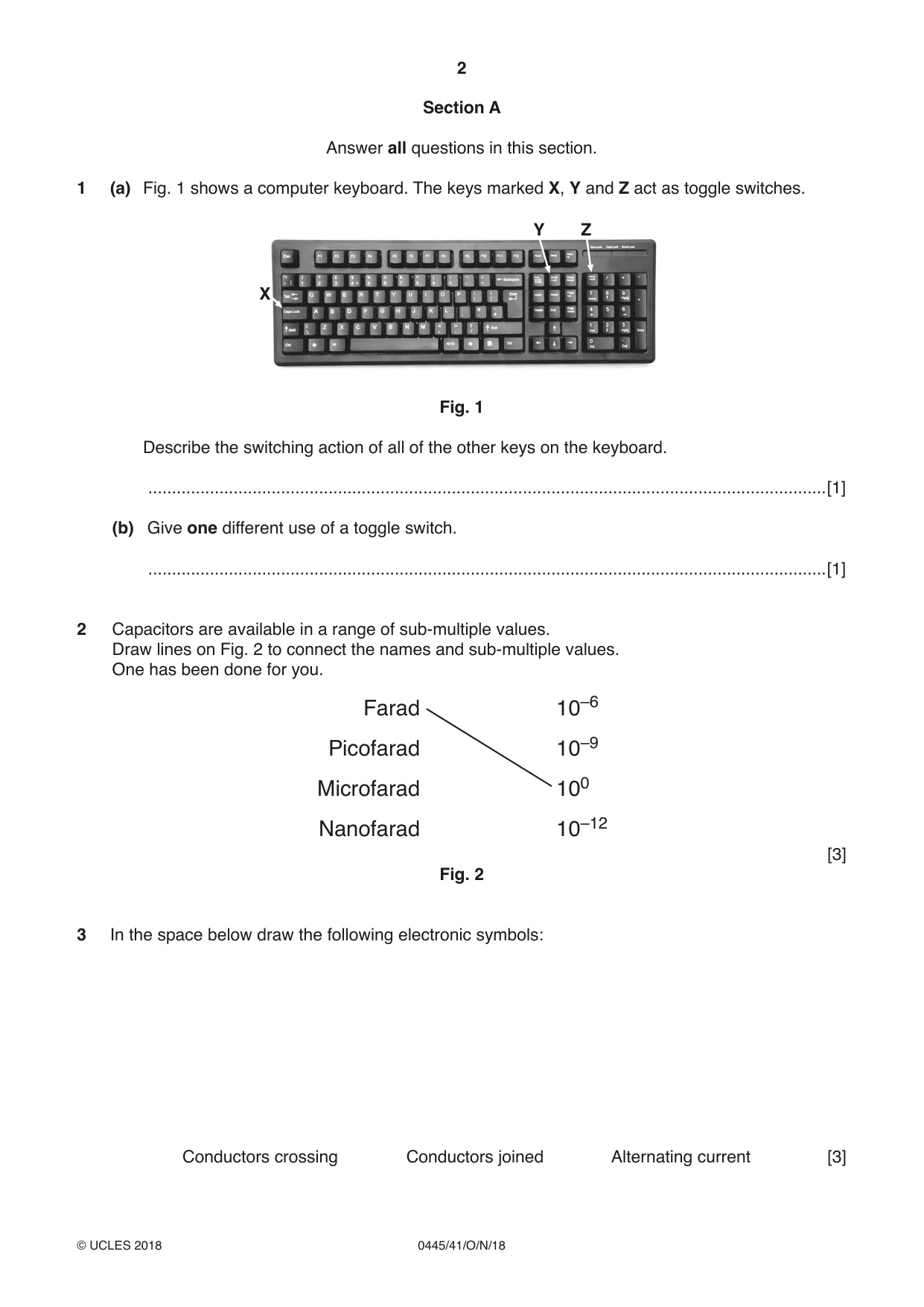
2 Capacitors are available in a range of sub-multiple values. Draw lines on Fig. 2 to connect the names and sub-multiple values. One has been done for you. Farad 10–6 Picofarad 10–9 Microfarad 100 Nanofarad 10–12 [3] Fig. 2
Mark scheme: 2 3 No marks for more than three lines drawn. Picofarad Microfarad Nanofarad 10 0 10 -9 10 -12
Q3 · In the space below draw the following electronic symbols: Conductors crossing Conductors…
3 In the space below draw the following electronic symbols: Conductors crossing Conductors joined Alternating current [3]
Mark scheme: 3 3 without terminals. Accept either conductor crossing symbol. Accept either conductor joined symbol. Alternating current Conductors joined Conductors crossing
Q4 · Pneumatic cylinders can be used to produce motion
4 Pneumatic cylinders can be used to produce motion. (a) Describe the difference between a single acting cylinder (SAC) and a double acting cylinder (DAC). ................................................................................................................................................... ................................................................................................................................................... ...............................................................................................................................................[2] (b) State the type of motion produced by a pneumatic cylinder. ...............................................................................................................................................[1]
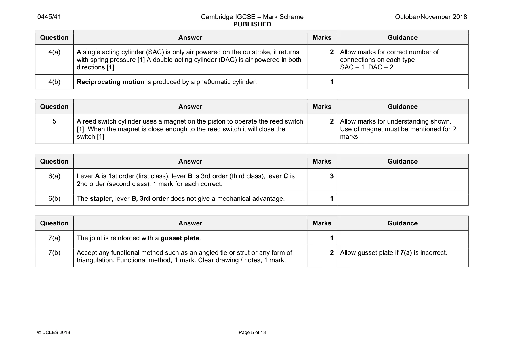
Mark scheme: 4(a) A single acting cylinder (SAC) is only air powered on the outstroke, it returns with spring pressure [1] A double acting cylinder (DAC) is air powered in both directions [1] 2 connections on each type SAC – 1 DAC – 2 4(b) Reciprocating motion is produced by a pne0umatic cylinder. 1
Q5 · Electronic and pneumatic systems can be integrated by using reed switch cylinders to…
5 Electronic and pneumatic systems can be integrated by using reed switch cylinders to determine the position of a pneumatic piston. Describe how a reed switch cylinder works. .......................................................................................................................................................... .......................................................................................................................................................... ......................................................................................................................................................[2]
Mark scheme: 5 A reed switch cylinder uses a magnet on the piston to operate the reed switch [1]. When the magnet is close enough to the reed switch it will close the switch [1] 2 Allow marks for understanding shown. Use of magnet must be mentioned for 2 marks.
Q6 · Three examples of a lever
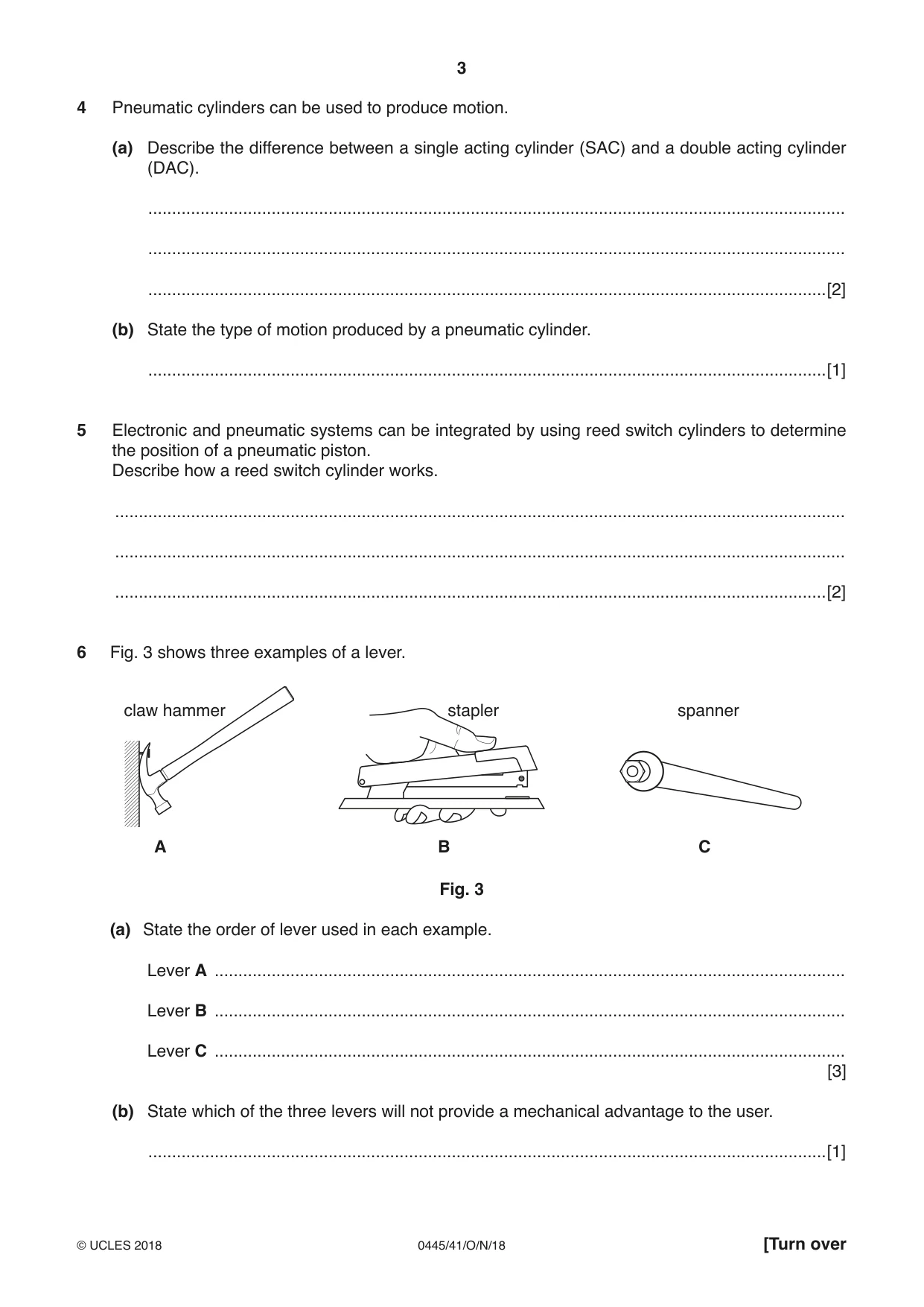
6 Fig. 3 shows three examples of a lever. claw hammer stapler spanner A B C Fig. 3 (a) State the order of lever used in each example. Lever A ..................................................................................................................................... Lever B ..................................................................................................................................... Lever C ..................................................................................................................................... [3] (b) State which of the three levers will not provide a mechanical advantage to the user. ...............................................................................................................................................[1]
Mark scheme: 6(a) Lever A is 1st order (first class), lever B is 3rd order (third class), lever C is 2nd order (second class), 1 mark for each correct. 3 6(b) The stapler, lever B, 3rd order does not give a mechanical advantage. 1
Q7 · A commonly used method of reinforcing a joint on a structure made from steel tube
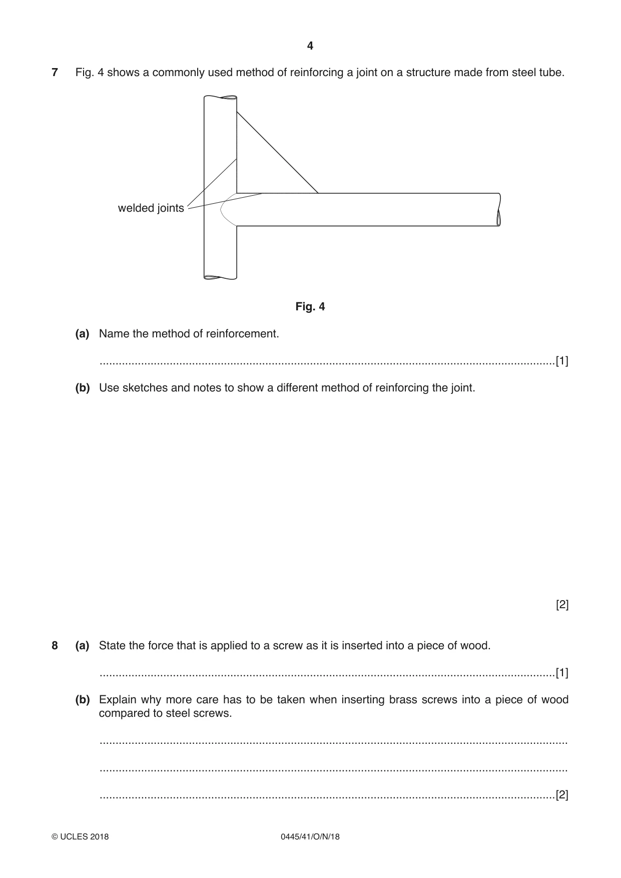
7 Fig. 4 shows a commonly used method of reinforcing a joint on a structure made from steel tube. welded joints Fig. 4 (a) Name the method of reinforcement. ...............................................................................................................................................[1] (b) Use sketches and notes to show a different method of reinforcing the joint. [2]
Mark scheme: 7(a) The joint is reinforced with a gusset plate. 1 7(b) Accept any functional method such as an angled tie or strut or any form of triangulation. Functional method, 1 mark. Clear drawing / notes, 1 mark. 2 Allow gusset plate if 7(a) is incorrect.
Q8 · State the force that is applied to a screw as it is inserted into a piece of wood
8 (a) State the force that is applied to a screw as it is inserted into a piece of wood. ...............................................................................................................................................[1] (b) Explain why more care has to be taken when inserting brass screws into a piece of wood compared to steel screws. ................................................................................................................................................... ................................................................................................................................................... ...............................................................................................................................................[2]
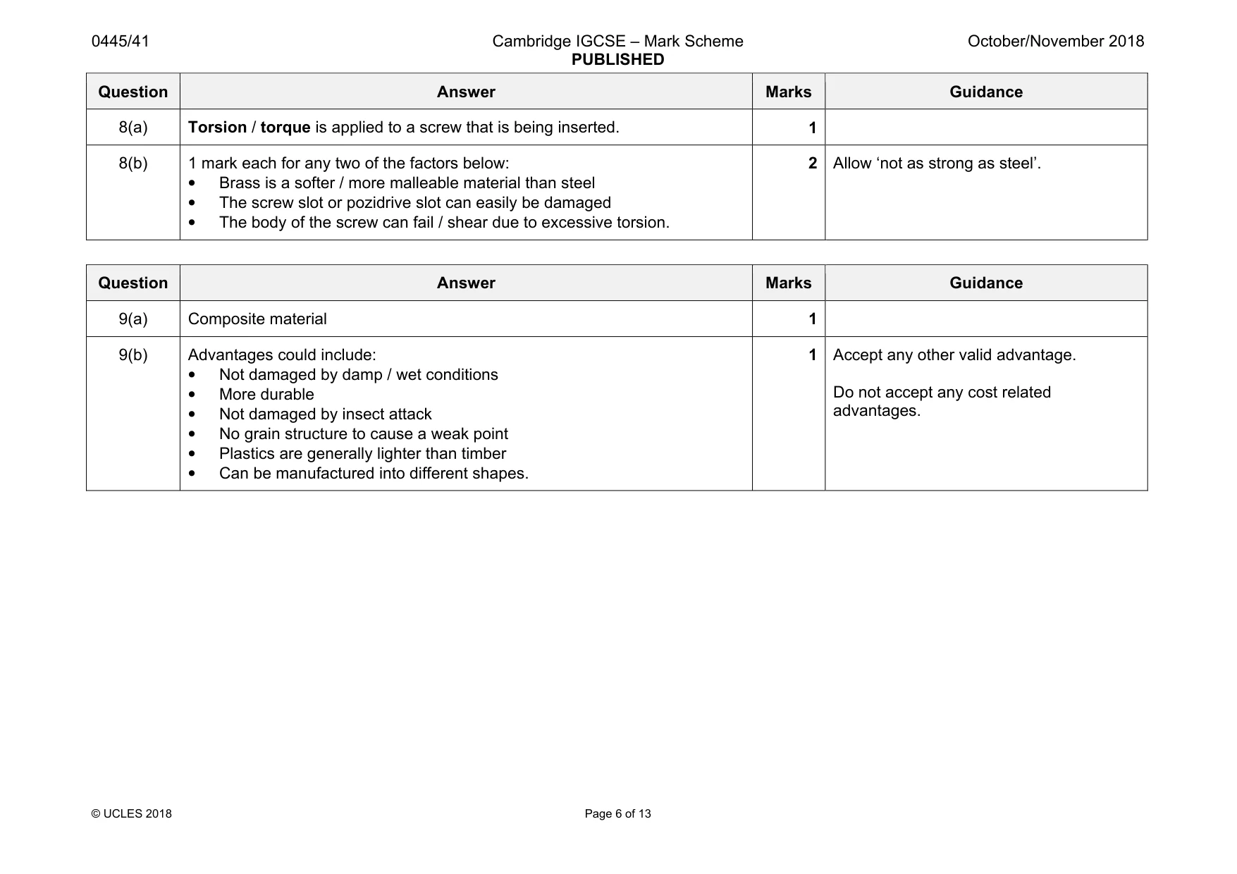
Mark scheme: 8(a) Torsion / torque is applied to a screw that is being inserted. 1 8(b) 1 mark each for any two of the factors below: • Brass is a softer / more malleable material than steel • The screw slot or pozidrive slot can easily be damaged • The body of the screw can fail / shear due to excessive torsion. 2 Allow ‘not as strong as steel’.
Q9 · Glass reinforced plastic (GRP) is a material that can be used for vehicle and boat…
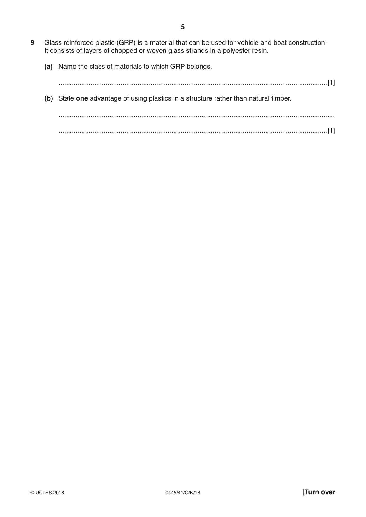
9 Glass reinforced plastic (GRP) is a material that can be used for vehicle and boat construction. It consists of layers of chopped or woven glass strands in a polyester resin. (a) Name the class of materials to which GRP belongs. ...............................................................................................................................................[1] (b) State one advantage of using plastics in a structure rather than natural timber. ................................................................................................................................................... ...............................................................................................................................................[1]
Mark scheme: 9(a) Composite material 1 9(b) Advantages could include: • Not damaged by damp / wet conditions • More durable • Not damaged by insect attack • No grain structure to cause a weak point • Plastics are generally lighter than timber • Can be manufactured into different shapes. 1 Accept any other valid advantage. Do not accept any cost related advantages.
Q10 · Draw and name one example of the structures named in each of the boxes below
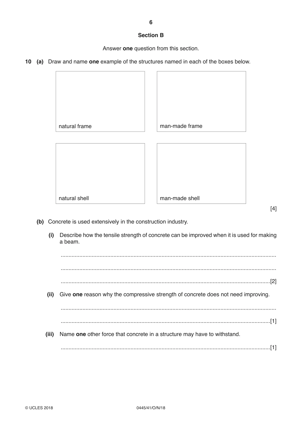
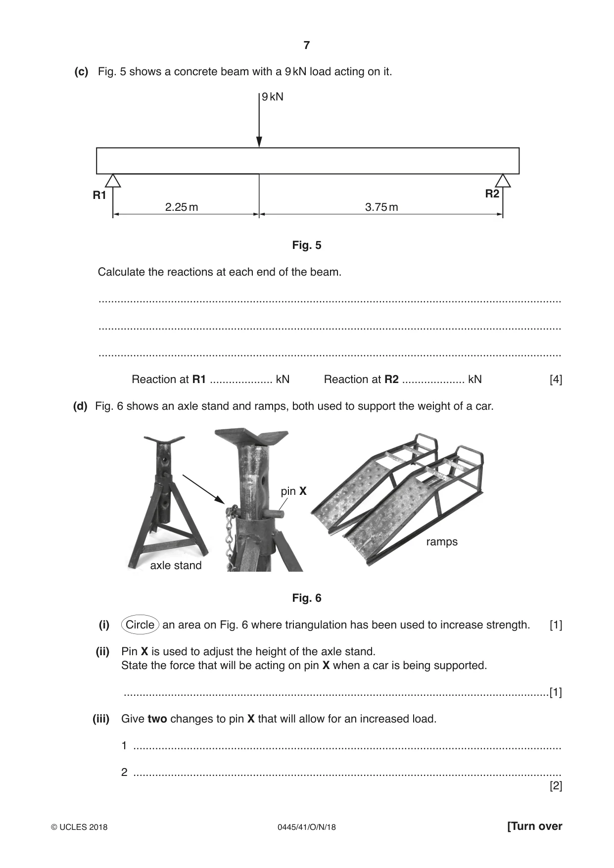
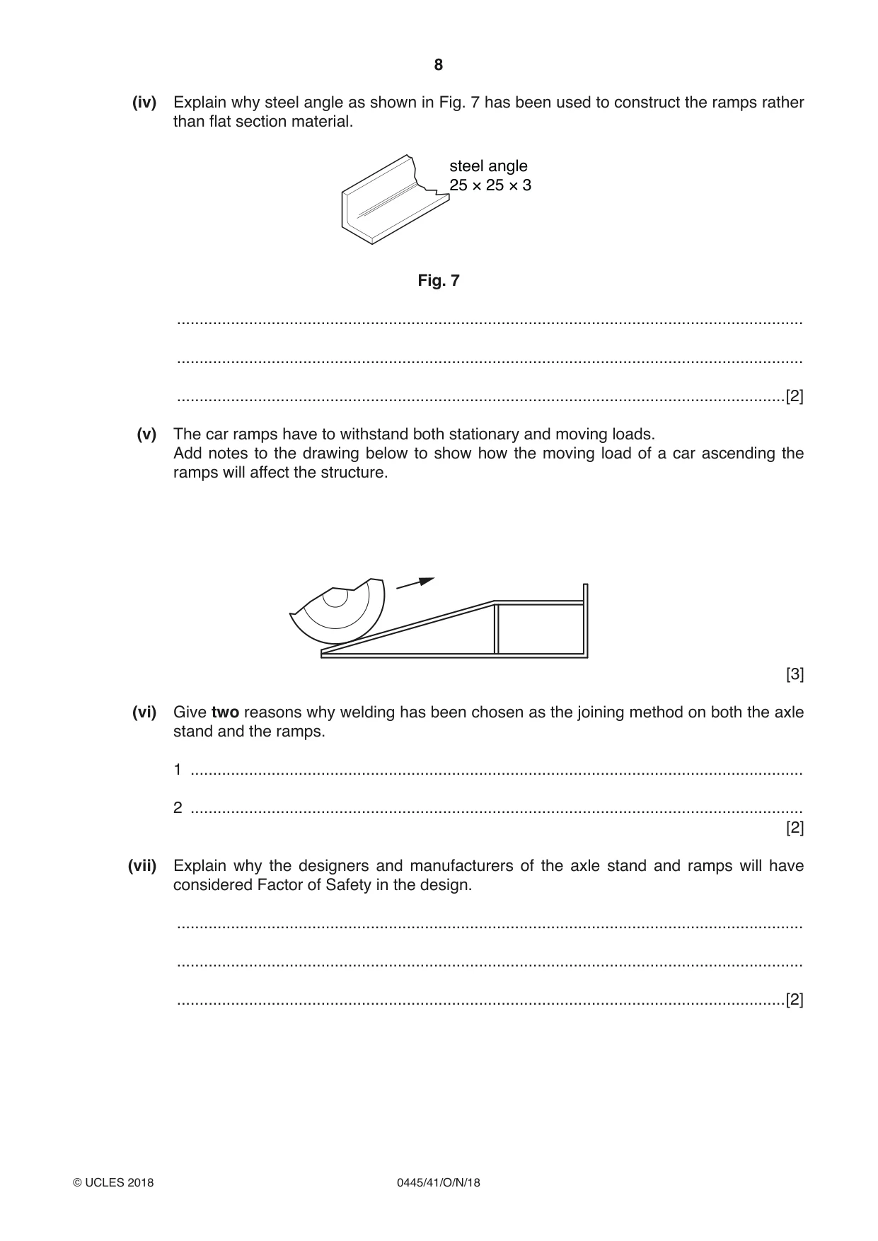
10 (a) Draw and name one example of the structures named in each of the boxes below. natural frame man-made frame natural shell man-made shell [4] (b) Concrete is used extensively in the construction industry. (i) Describe how the tensile strength of concrete can be improved when it is used for making a beam. ........................................................................................................................................... ........................................................................................................................................... .......................................................................................................................................[2] (ii) Give one reason why the compressive strength of concrete does not need improving. ........................................................................................................................................... .......................................................................................................................................[1] (iii) Name one other force that concrete in a structure may have to withstand. .......................................................................................................................................[1] (c) Fig. 5 shows a concrete beam with a 9 kN load acting on it. 9 kN R1 R2 2.25 m 3.75 m Fig. 5 Calculate the reactions at each end of the beam. ................................................................................................................................................... ................................................................................................................................................... ................................................................................................................................................... Reaction at R1 .................... kN Reaction at R2 .................... kN [4] (d) Fig. 6 shows an axle stand and ramps, both used to support the weight of a car. pin X ramps axle stand Fig. 6 (i) Circle an area on Fig. 6 where triangulation has been used to increase strength. [1] (ii) Pin X is used to adjust the height of the axle stand. State the force that will be acting on pin X when a car is being supported. .......................................................................................................................................[1] (iii) Give two changes to pin X that will allow for an increased load. 1 ........................................................................................................................................ 2 ........................................................................................................................................ [2] (iv) Explain why steel angle as shown in Fig. 7 has been used to construct the ramps rather than flat section material. steel angle 25 × 25 × 3 Fig. 7 ........................................................................................................................................... ........................................................................................................................................... .......................................................................................................................................[2] (v) The car ramps have to withstand both stationary and moving loads. Add notes to the drawing below to show how the moving load of a car ascending the ramps will affect the structure. [3] (vi) Give two reasons why welding has been chosen as the joining method on both the axle stand and the ramps. 1 ........................................................................................................................................ 2 ........................................................................................................................................ [2] (vii) Explain why the designers and manufacturers of the axle stand and ramps will have considered Factor of Safety in the design. ........................................................................................................................................... ........................................................................................................................................... .......................................................................................................................................[2]
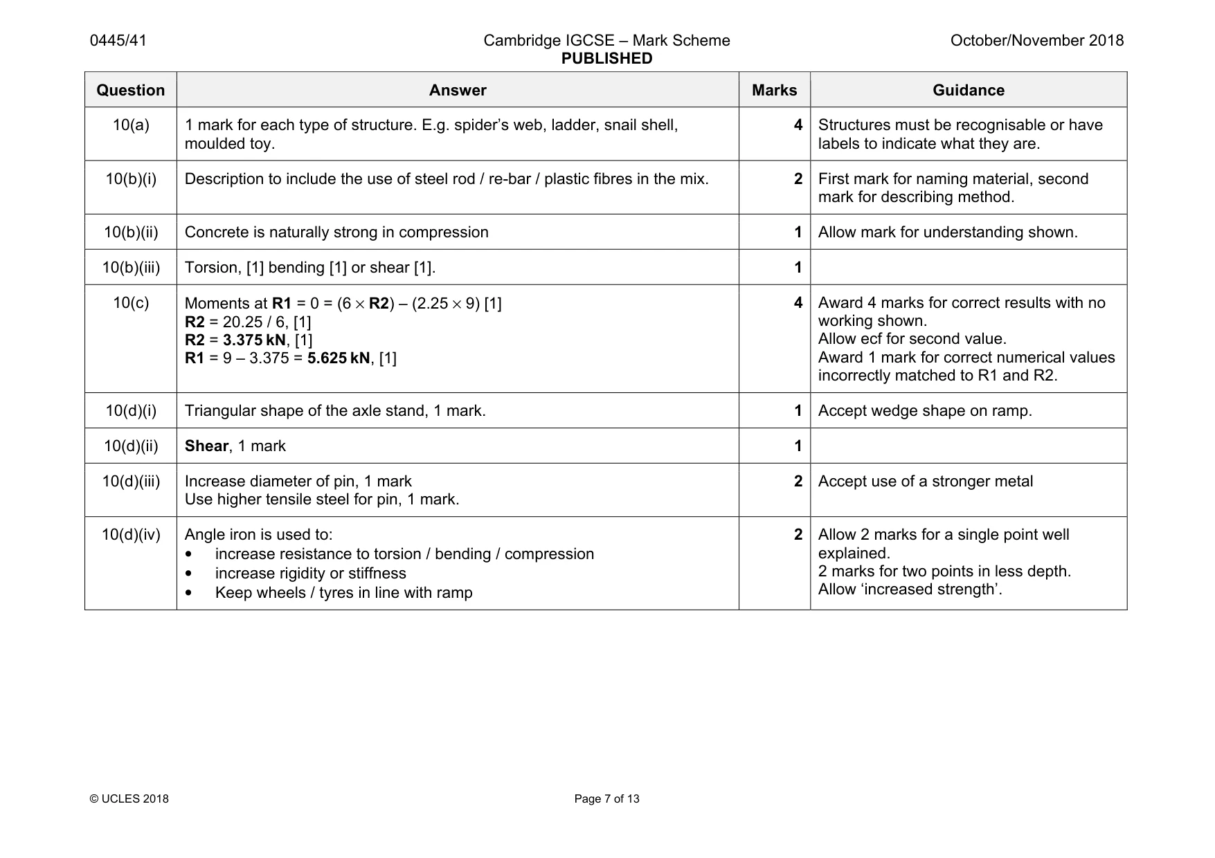
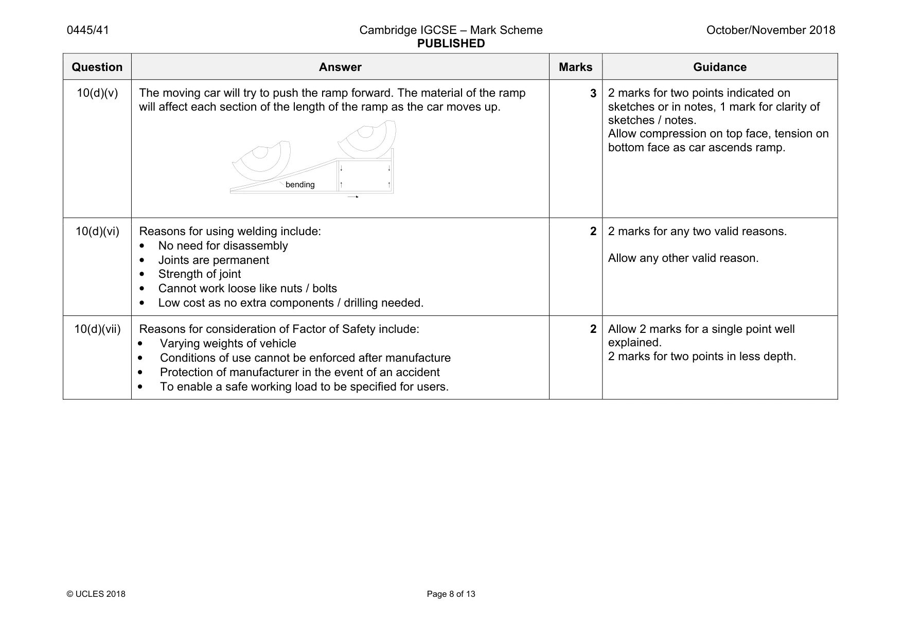
Mark scheme: 10(a) 1 mark for each type of structure. E.g. spider’s web, ladder, snail shell, moulded toy. 4 labels to indicate what they are. 10(b)(i) Description to include the use of steel rod / re-bar / plastic fibres in the mix. 2 First mark for naming material, second mark for describing method. 10(b)(ii) Concrete is naturally strong in compression 1 Allow mark for understanding shown. 10(b)(iii) Torsion, [1] bending [1] or shear [1]. 1 10(c) Moments at R1 = 0 = (6 × R2) – (2.25 × 9) [1] R2 = 20.25 / 6, [1] R2 = 3.375 kN, [1] R1 = 9 – 3.375 = 5.625 kN, [1] 4 Award 4 marks for correct results with no working shown. Allow ecf for second value. Award 1 mark for correct numerical values incorrectly matched to R1 and R2. 10(d)(i) Triangular shape of the axle stand, 1 mark. 1 Accept wedge shape on ramp. 10(d)(ii) Shear, 1 mark 1 10(d)(iii) Increase diameter of pin, 1 mark Use higher tensile steel for pin, 1 mark. 2 Accept use of a stronger metal 10(d)(iv) Angle iron is used to: • increase resistance to torsion / bending / compression • increase rigidity or stiffness • Keep wheels / tyres in line with ramp 2 Allow 2 marks for a single point well explained. 2 marks for two points in less depth. Allow ‘increased strength’. Question Answer Marks Guidance 10(d)(v) The moving car will try to push the ramp forward. The material of the ramp will affect each section of the length of the ramp as the car moves up. 3 2 marks for two points indicated on sketches or in notes, 1 mark for clarity of sketches / notes. Allow compression on top face, tension on bottom face as car ascends ramp. 10(d)(vi) Reasons for using welding include: • No need for disassembly • Joints are permanent • Strength of joint • Cannot work loose like nuts / bolts • Low cost as no extra components / drilling needed. 2 2 marks for any two valid reasons. Allow any other valid reason. 10(d)(vii) Reasons for consideration of Factor of Safety include: • Varying weights of vehicle • Conditions of use cannot be enforced after manufacture • Protection of manufacturer in the event of an accident • To enable a safe working load to be specified for users. 2 Allow 2 marks for a single point well explained. 2 marks for two points in less depth. bending
Q11 · Give two reasons for using gears in a mechanism
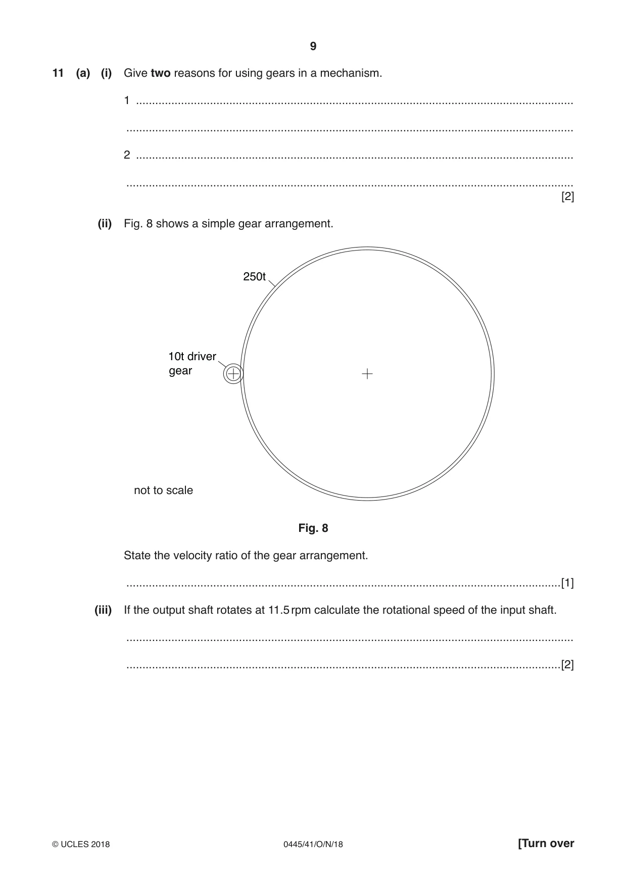
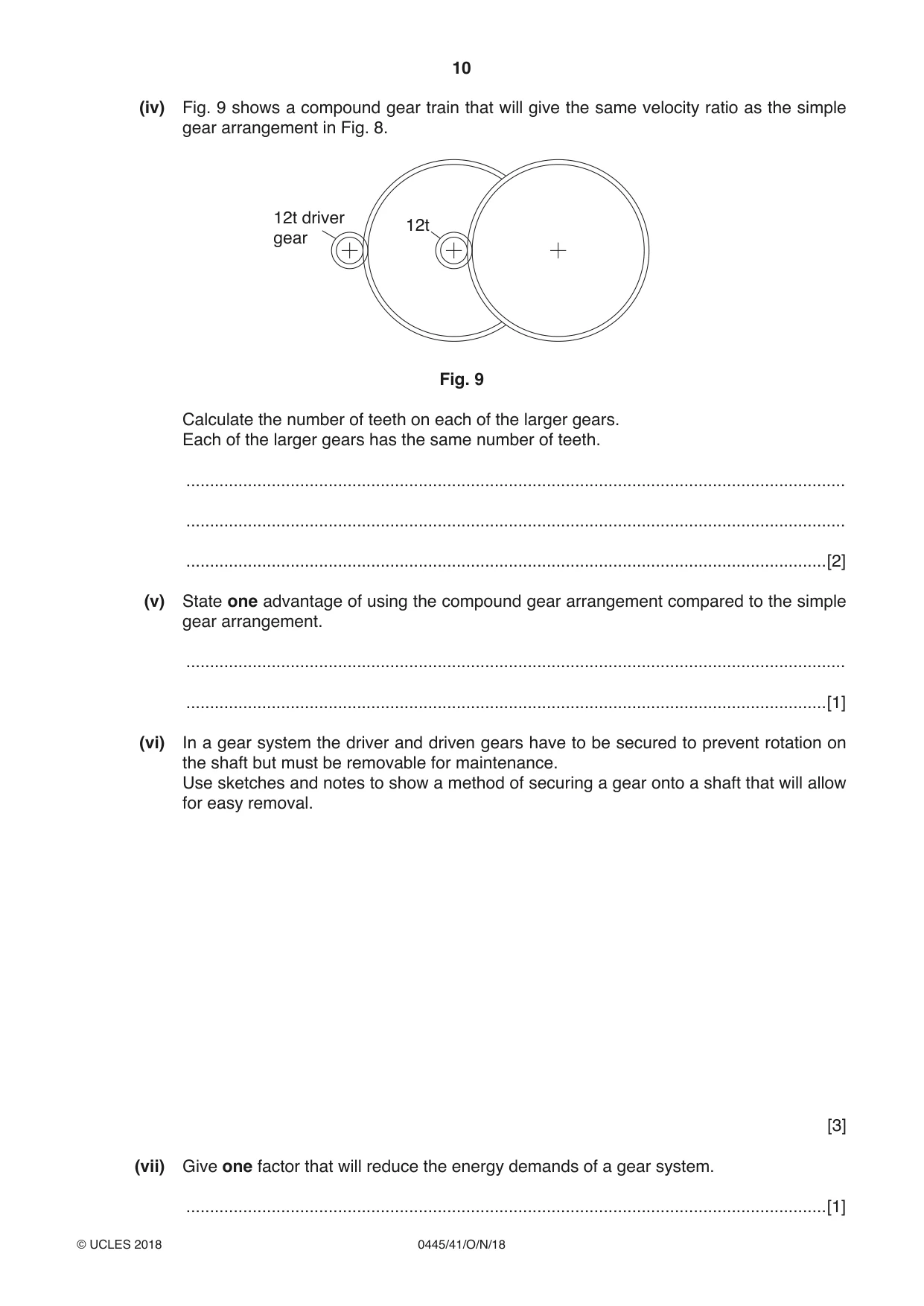
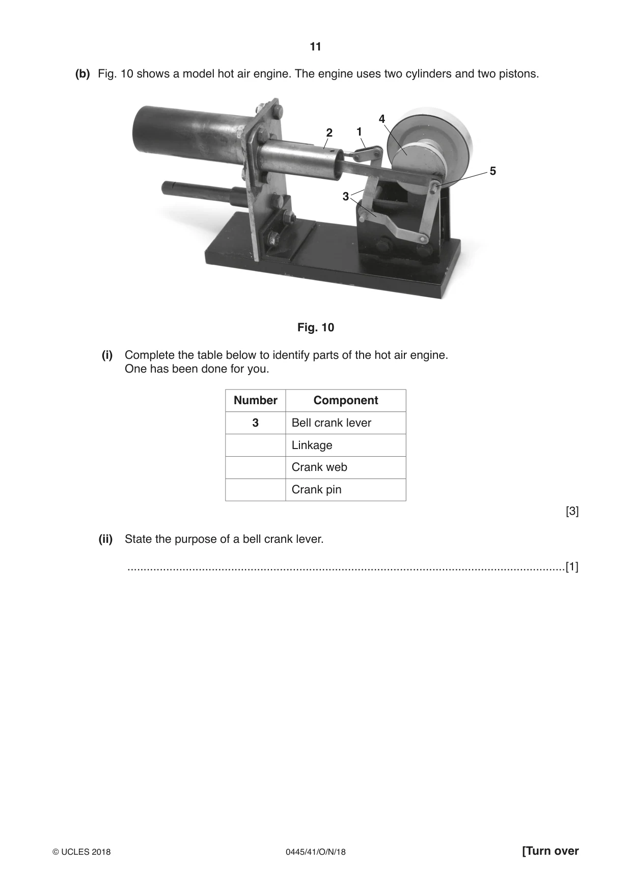
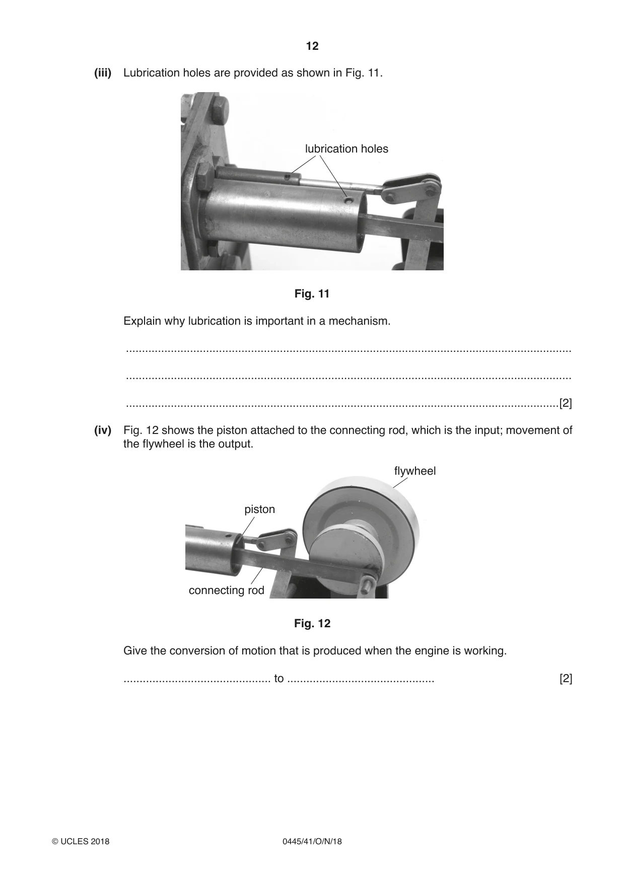
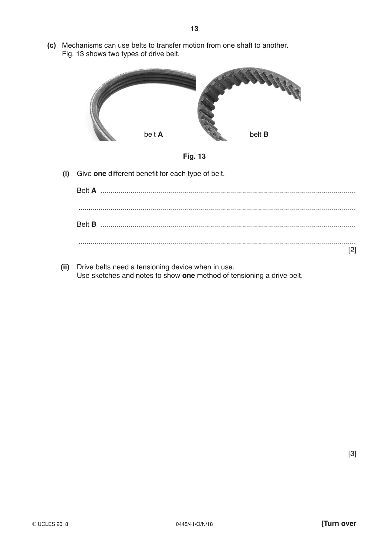
11 (a) (i) Give two reasons for using gears in a mechanism. 1 ........................................................................................................................................ ........................................................................................................................................... 2 ........................................................................................................................................ ........................................................................................................................................... [2] (ii) Fig. 8 shows a simple gear arrangement. 250t 10t driver gear not to scale Fig. 8 State the velocity ratio of the gear arrangement. .......................................................................................................................................[1] (iii) If the output shaft rotates at 11.5 rpm calculate the rotational speed of the input shaft. ........................................................................................................................................... .......................................................................................................................................[2] (iv) Fig. 9 shows a compound gear train that will give the same velocity ratio as the simple gear arrangement in Fig. 8. 12t driver 12t gear Fig. 9 Calculate the number of teeth on each of the larger gears. Each of the larger gears has the same number of teeth. ........................................................................................................................................... ........................................................................................................................................... .......................................................................................................................................[2] (v) State one advantage of using the compound gear arrangement compared to the simple gear arrangement. ........................................................................................................................................... .......................................................................................................................................[1] (vi) In a gear system the driver and driven gears have to be secured to prevent rotation on the shaft but must be removable for maintenance. Use sketches and notes to show a method of securing a gear onto a shaft that will allow for easy removal. [3] (vii) Give one factor that will reduce the energy demands of a gear system. .......................................................................................................................................[1] (b) Fig. 10 shows a model hot air engine. The engine uses two cylinders and two pistons. 4 2 1 5 3 Fig. 10 (i) Complete the table below to identify parts of the hot air engine. One has been done for you. Number Component 3 Bell crank lever Linkage Crank web Crank pin [3] (ii) State the purpose of a bell crank lever. .......................................................................................................................................[1] (iii) Lubrication holes are provided as shown in Fig. 11. lubrication holes Fig. 11 Explain why lubrication is important in a mechanism. ........................................................................................................................................... ........................................................................................................................................... .......................................................................................................................................[2] (iv) Fig. 12 shows the piston attached to the connecting rod, which is the input; movement of the flywheel is the output. flywheel piston connecting rod Fig. 12 Give the conversion of motion that is produced when the engine is working. .............................................. to .............................................. [2] (c) Mechanisms can use belts to transfer motion from one shaft to another. Fig. 13 shows two types of drive belt. belt A belt B Fig. 13 (i) Give one different benefit for each type of belt. Belt A ................................................................................................................................ ........................................................................................................................................... Belt B ................................................................................................................................ ........................................................................................................................................... [2] (ii) Drive belts need a tensioning device when in use. Use sketches and notes to show one method of tensioning a drive belt. [3]
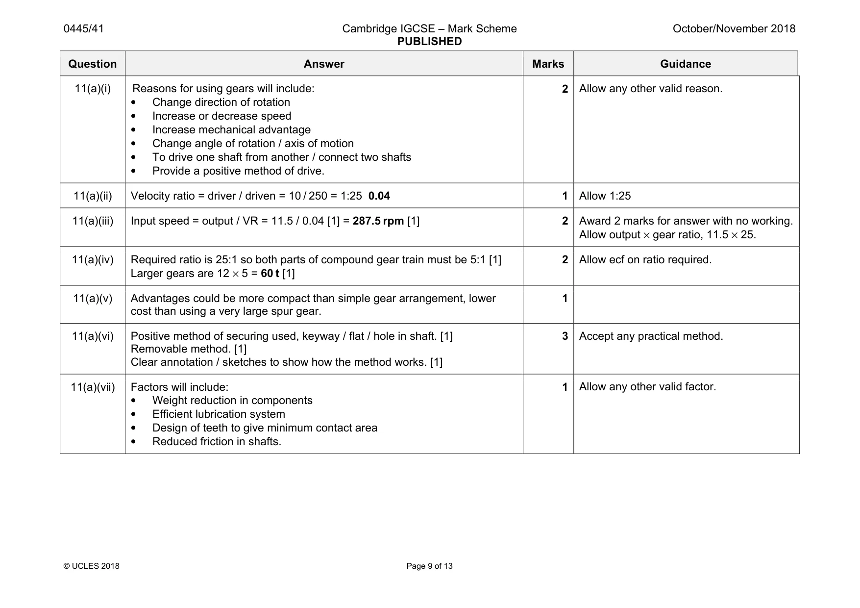
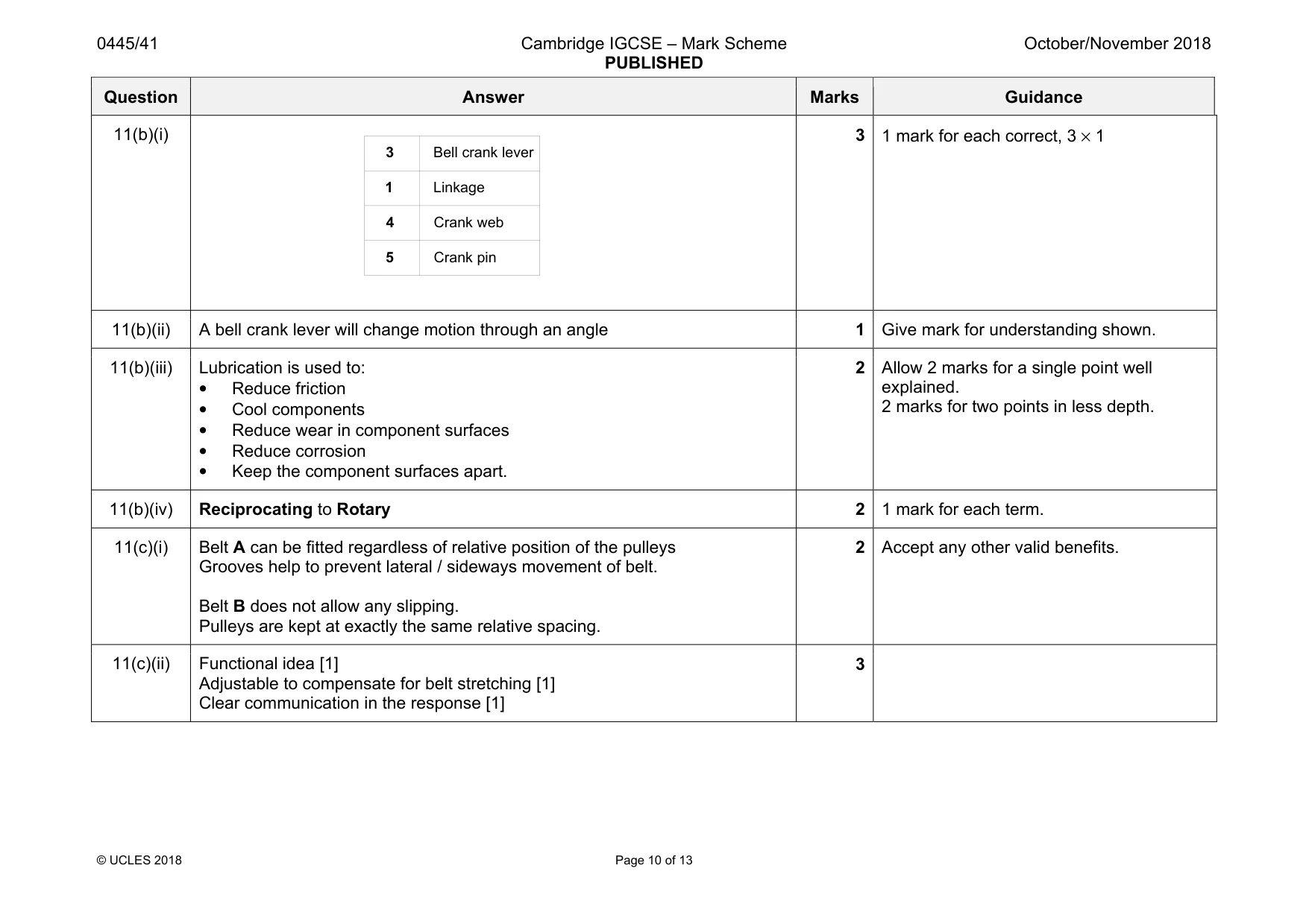
Mark scheme: 11(a)(i) Reasons for using gears will include: • Change direction of rotation • Increase or decrease speed • Increase mechanical advantage • Change angle of rotation / axis of motion • To drive one shaft from another / connect two shafts • Provide a positive method of drive. 2 Allow any other valid reason. 11(a)(ii) Velocity ratio = driver / driven = 10 / 250 = 1:25 0.04 1 Allow 1:25 11(a)(iii) Input speed = output / VR = 11.5 / 0.04 [1] = 287.5 rpm [1] 2 Award 2 marks for answer with no working. Allow output × gear ratio, 11.5 × 25. 11(a)(iv) Required ratio is 25:1 so both parts of compound gear train must be 5:1 [1] Larger gears are 12 × 5 = 60 t [1] 2 Allow ecf on ratio required. 11(a)(v) Advantages could be more compact than simple gear arrangement, lower cost than using a very large spur gear. 1 11(a)(vi) Positive method of securing used, keyway / flat / hole in shaft. [1] Removable method. [1] Clear annotation / sketches to show how the method works. [1] 3 Accept any practical method. 11(a)(vii) Factors will include: • Weight reduction in components • Efficient lubrication system • Design of teeth to give minimum contact area • Reduced friction in shafts. 1 Allow any other valid factor. Question Answer Marks Guidance 11(b)(i) 3 1 mark for each correct, 3 × 1 11(b)(ii) A bell crank lever will change motion through an angle 1 Give mark for understanding shown. 11(b)(iii) Lubrication is used to: • Reduce friction • Cool components • Reduce wear in component surfaces • Reduce corrosion • Keep the component surfaces apart. 2 Allow 2 marks for a single point well explained. 2 marks for two points in less depth. 11(b)(iv) Reciprocating to Rotary 2 1 mark for each term. 11(c)(i) Belt A can be fitted regardless of relative position of the pulleys Grooves help to prevent lateral / sideways movement of belt. Belt B does not allow any slipping. Pulleys are kept at exactly the same relative spacing. 2 Accept any other valid benefits. 11(c)(ii) Functional idea [1] Adjustable to compensate for belt stretching [1] Clear communication in the response [1] 3 3 1 4 5 Bell crank lever Linkage Crank web Crank pin
Q12 · Electronic components can be either polarised or non polarised
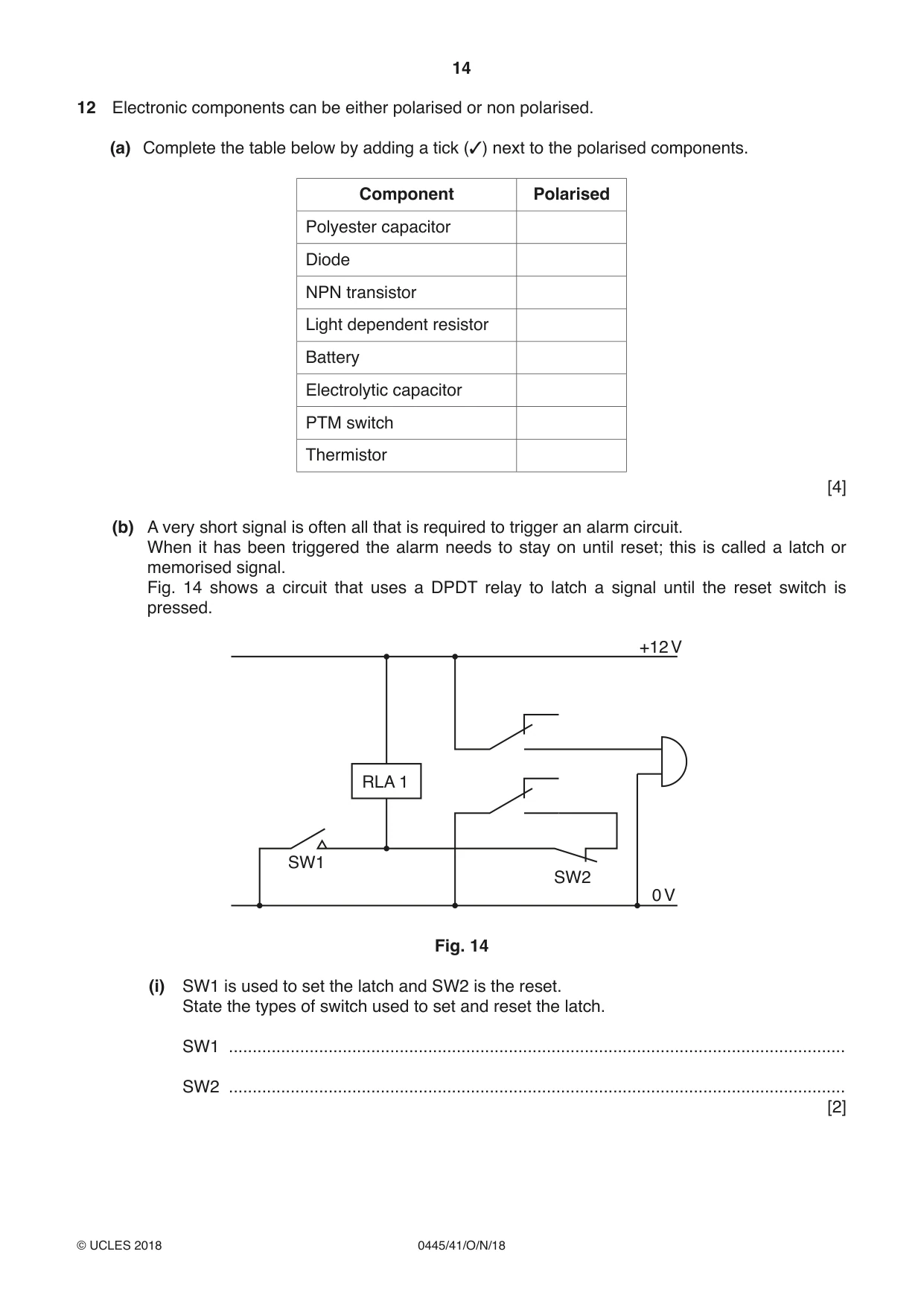
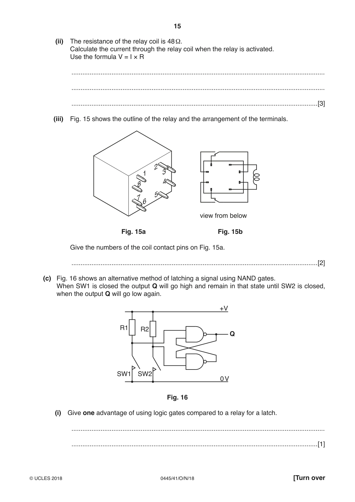
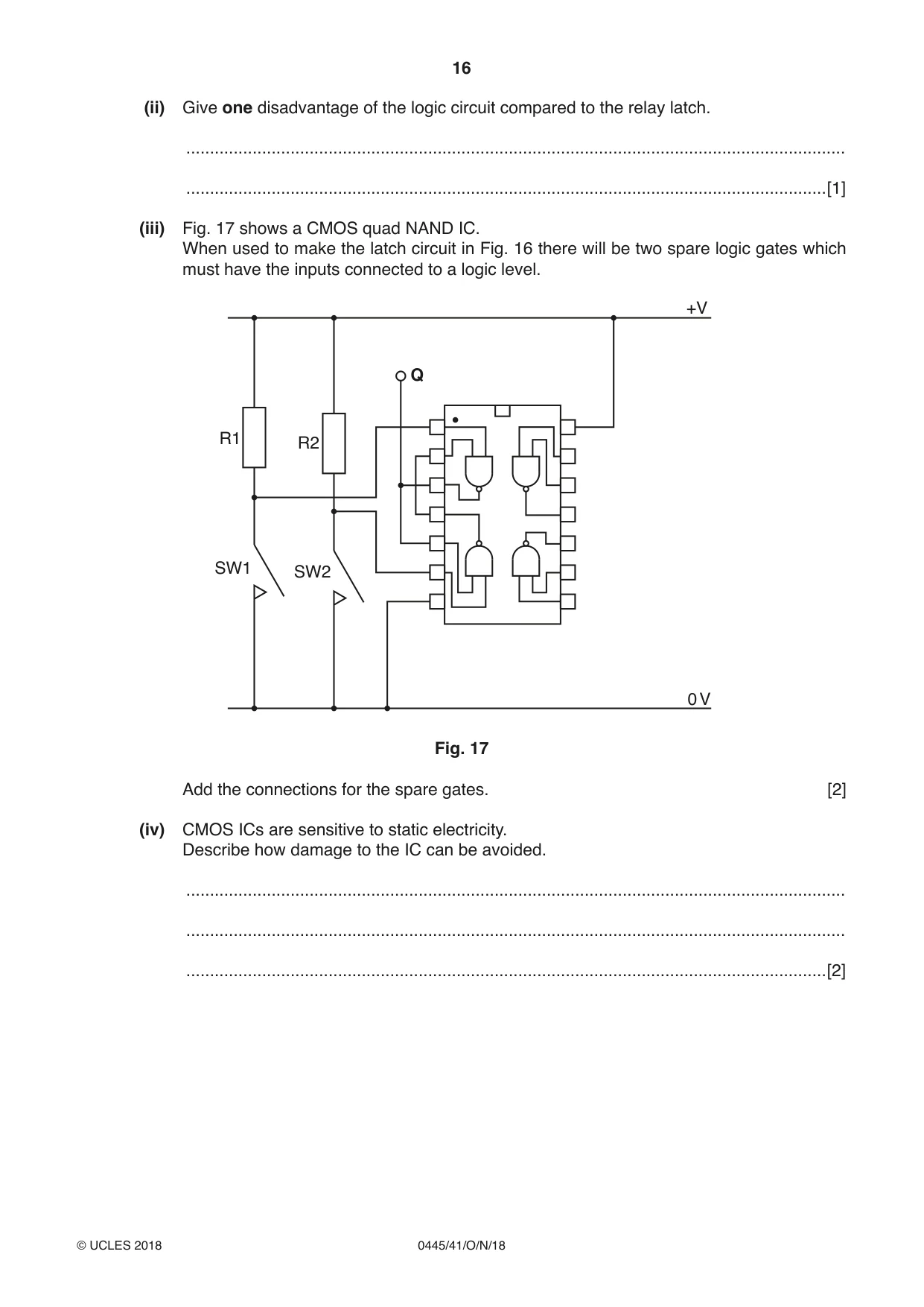
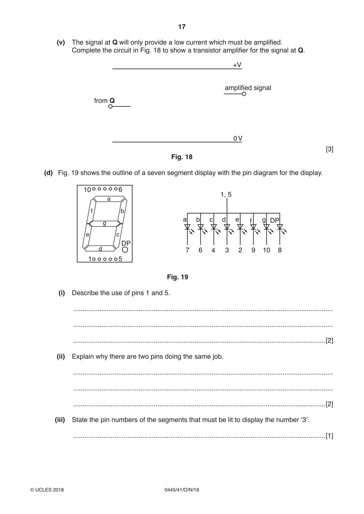
12 Electronic components can be either polarised or non polarised. (a) Complete the table below by adding a tick (3) next to the polarised components. Component Polarised Polyester capacitor Diode NPN transistor Light dependent resistor Battery Electrolytic capacitor PTM switch Thermistor [4] (b) A very short signal is often all that is required to trigger an alarm circuit. When it has been triggered the alarm needs to stay on until reset; this is called a latch or memorised signal. Fig. 14 shows a circuit that uses a DPDT relay to latch a signal until the reset switch is pressed. +12 V RLA 1 SW1 SW2 0 V Fig. 14 (i) SW1 is used to set the latch and SW2 is the reset. State the types of switch used to set and reset the latch. SW1 .................................................................................................................................. SW2 .................................................................................................................................. [2] (ii) The resistance of the relay coil is 48 Ω. Calculate the current through the relay coil when the relay is activated. Use the formula V = I × R ........................................................................................................................................... ........................................................................................................................................... .......................................................................................................................................[3] (iii) Fig. 15 shows the outline of the relay and the arrangement of the terminals. view from below Fig. 15a Fig. 15b Give the numbers of the coil contact pins on Fig. 15a. .......................................................................................................................................[2] (c) Fig. 16 shows an alternative method of latching a signal using NAND gates. When SW1 is closed the output Q will go high and remain in that state until SW2 is closed, when the output Q will go low again. +V R1 R2 Q SW1 SW2 0 V Fig. 16 (i) Give one advantage of using logic gates compared to a relay for a latch. ........................................................................................................................................... .......................................................................................................................................[1] (ii) Give one disadvantage of the logic circuit compared to the relay latch. ........................................................................................................................................... .......................................................................................................................................[1] (iii) Fig. 17 shows a CMOS quad NAND IC. When used to make the latch circuit in Fig. 16 there will be two spare logic gates which must have the inputs connected to a logic level. +V Q R1 R2 SW1 SW2 0 V Fig. 17 Add the connections for the spare gates. [2] (iv) CMOS ICs are sensitive to static electricity. Describe how damage to the IC can be avoided. ........................................................................................................................................... ........................................................................................................................................... .......................................................................................................................................[2]
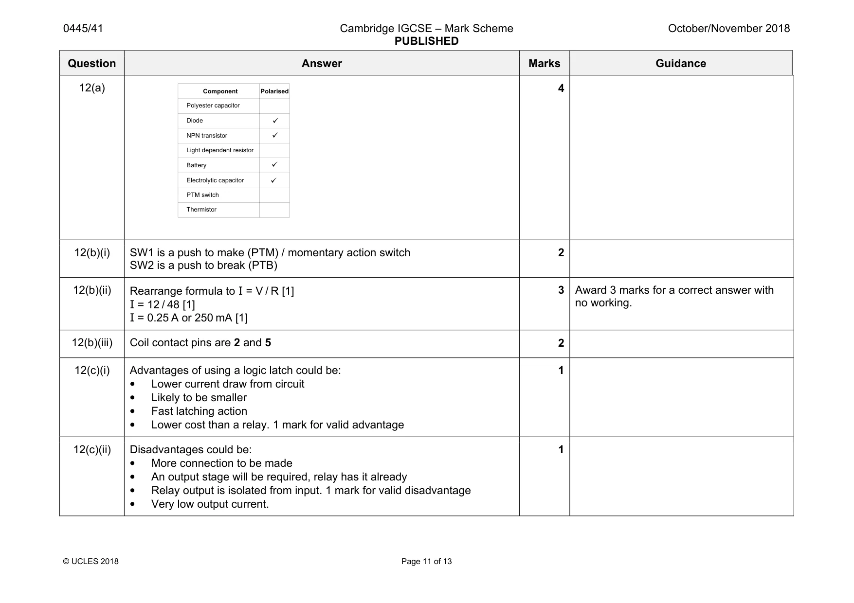
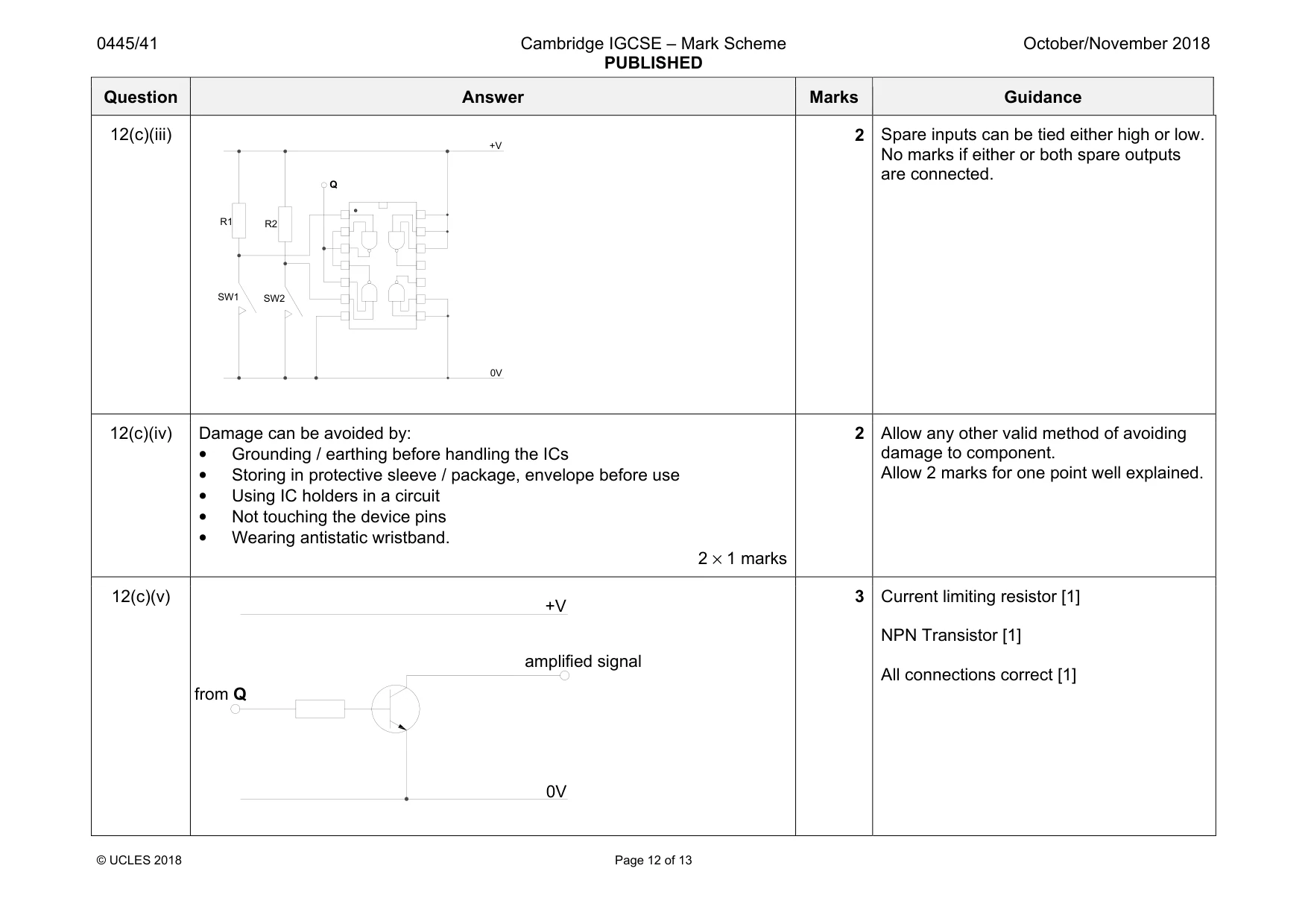
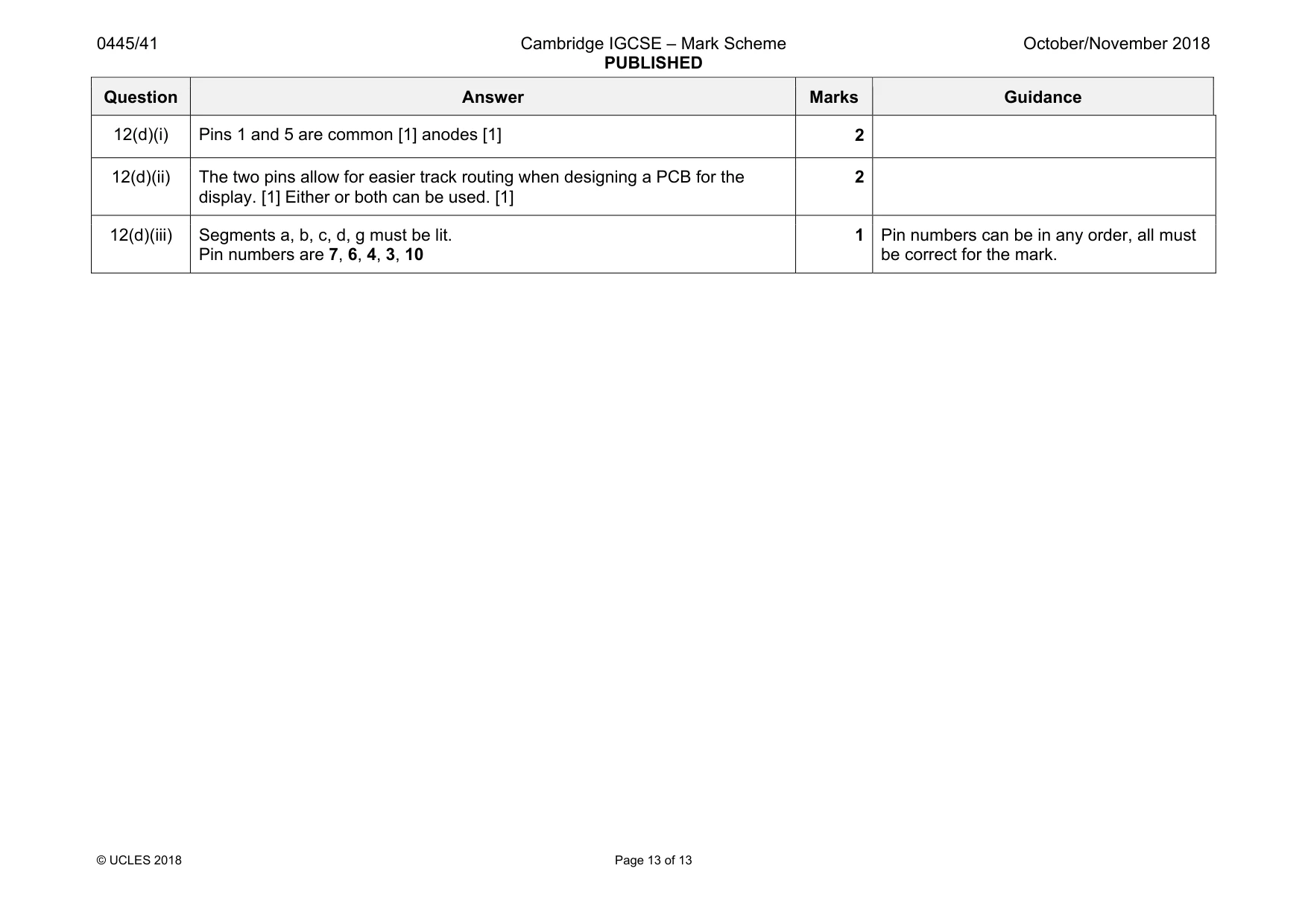
Mark scheme: 12(a) 4 12(b)(i) SW1 is a push to make (PTM) / momentary action switch SW2 is a push to break (PTB) 2 12(b)(ii) Rearrange formula to I = V / R [1] I = 12 / 48 [1] I = 0.25 A or 250 mA [1] 3 Award 3 marks for a correct answer with no working. 12(b)(iii) Coil contact pins are 2 and 5 2 12(c)(i) Advantages of using a logic latch could be: • Lower current draw from circuit • Likely to be smaller • Fast latching action • Lower cost than a relay. 1 mark for valid advantage 1 12(c)(ii) Disadvantages could be: • More connection to be made • An output stage will be required, relay has it already • Relay output is isolated from input. 1 mark for valid disadvantage • Very low output current. 1 Polyester capacitor Diode NPN transistor Light dependent resistor Battery Electrolytic capacitor PTM switch Component Polarised 9 9 9 9 Thermistor Question Answer Marks Guidance 12(c)(iii) 2 Spare inputs can be tied either high or low. No marks if either or both spare outputs are connected. 12(c)(iv) Damage can be avoided by: • Grounding / earthing before handling the ICs • Storing in protective sleeve / package, envelope before use • Using IC holders in a circuit • Not touching the device pins • Wearing antistatic wristband. 2 × 1 marks 2 Allow any other valid method of avoiding damage to component. Allow 2 marks for one point well explained. 12(c)(v) 3 Current limiting resistor [1] NPN Transistor [1] All connections correct [1] from Q 0V +V amplified signal SW1 SW2 R1 R2 0V +V Q Question Answer Marks Guidance 12(d)(i) Pins 1 and 5 are common [1] anodes [1] 2 12(d)(ii) The two pins allow for easier track routing when designing a PCB for the display. [1] Either or both can be used. [1] 2 12(d)(iii) Segments a, b, c, d, g must be lit. Pin numbers are 7, 6, 4, 3, 10 1 Pin numbers can be in any order, all must be correct for the mark.
What was in this paper
The subtopics covered by these 12 questions, and how many questions each got. Open one in a new tab to see every Cambridge question on it.
What you needed in this session
Cambridge’s own grade thresholds for 2018 Oct/Nov, Paper 4 · Variant 1. A higher threshold means an easier paper — the bar moves with how the cohort did.