Cambridge IGCSE Design and Technology 0445 — 2018 May/June Paper 4 · Variant 1
0445/41/M/J/18 · 12 questions · 50 marks · ≈56 min
The question paper and its mark scheme, free to read here and free to download. This is Cambridge’s own paper, exactly as it was sat.
Question paper20 pages

Mark scheme12 pages
Answers below. Sit the paper first if you are practising.

Questions as text
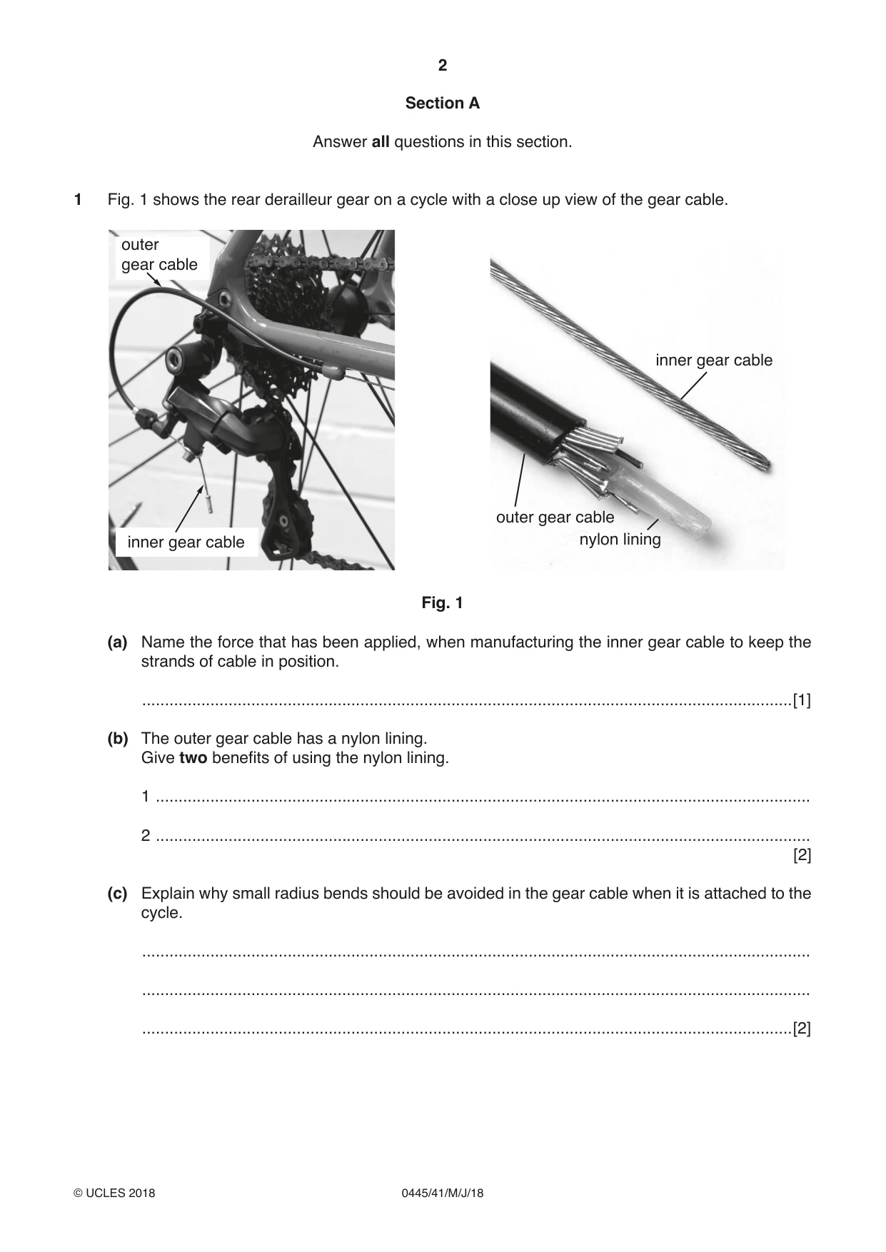
Q1 · The rear derailleur gear on a cycle with a close up view of the gear cable
1 Fig. 1 shows the rear derailleur gear on a cycle with a close up view of the gear cable. outer gear cable inner gear cable outer gear cable inner gear cable nylon lining Fig. 1 (a) Name the force that has been applied, when manufacturing the inner gear cable to keep the strands of cable in position. ...............................................................................................................................................[1] (b) The outer gear cable has a nylon lining. Give two benefits of using the nylon lining. 1 ................................................................................................................................................ 2 ................................................................................................................................................ [2] (c) Explain why small radius bends should be avoided in the gear cable when it is attached to the cycle. ................................................................................................................................................... ................................................................................................................................................... ...............................................................................................................................................[2]
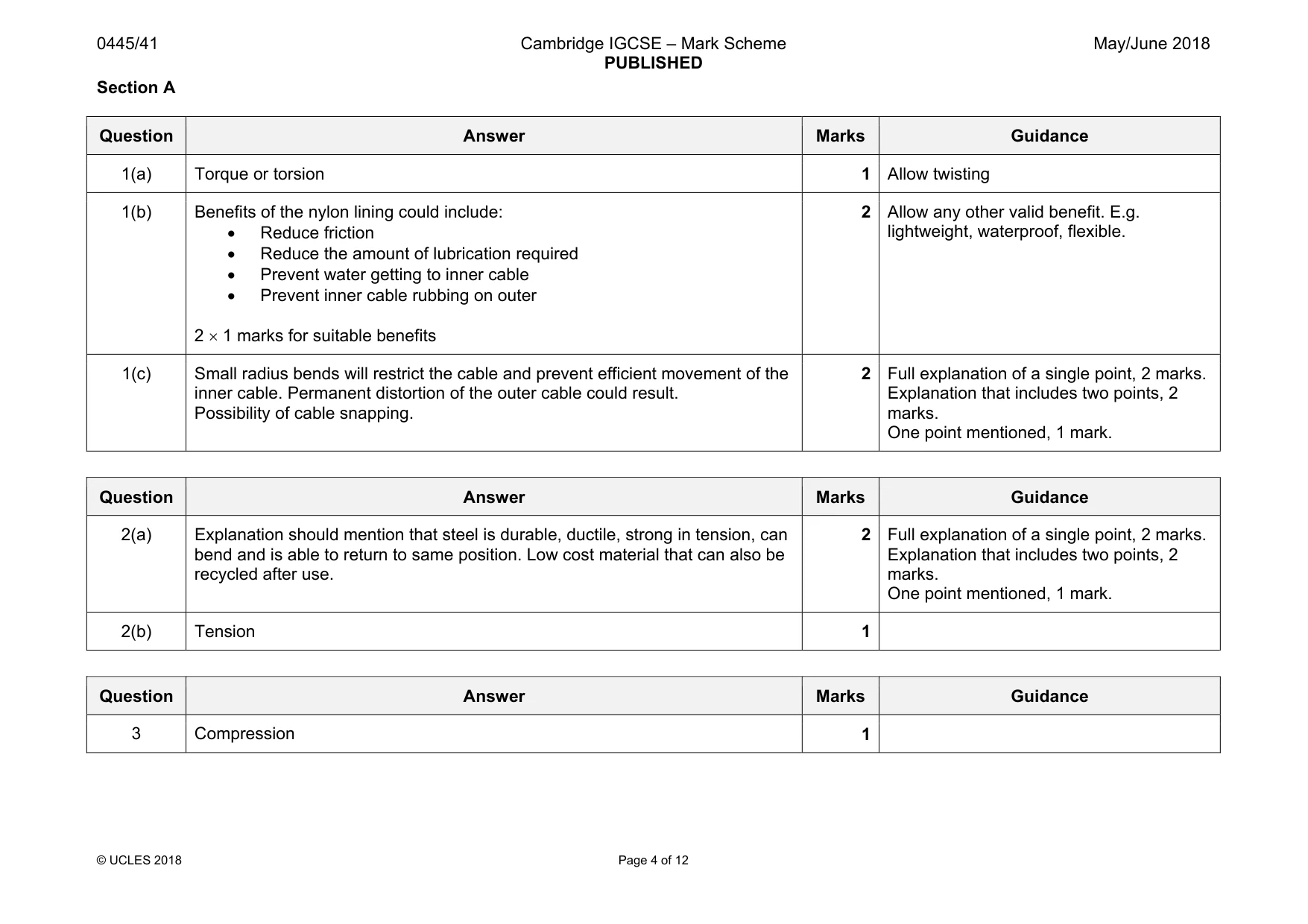
Mark scheme: 1(a) Torque or torsion 1 Allow twisting 1(b) Benefits of the nylon lining could include: • Reduce friction • Reduce the amount of lubrication required • Prevent water getting to inner cable • Prevent inner cable rubbing on outer 2 × 1 marks for suitable benefits 2 Allow any other valid benefit. E.g. lightweight, waterproof, flexible. 1(c) Small radius bends will restrict the cable and prevent efficient movement of the inner cable. Permanent distortion of the outer cable could result. Possibility of cable snapping. 2 Full explanation of a single point, 2 marks. Explanation that includes two points, 2 marks. One point mentioned, 1 mark.
Q2 · Explain why steel is used for control cables on a cycle
2 (a) Explain why steel is used for control cables on a cycle. ................................................................................................................................................... ................................................................................................................................................... ...............................................................................................................................................[2] (b) State the force being used when a control cable is operated. ...............................................................................................................................................[1]
Mark scheme: 2(a) Explanation should mention that steel is durable, ductile, strong in tension, can bend and is able to return to same position. Low cost material that can also be recycled after use. 2 Full explanation of a single point, 2 marks. Explanation that includes two points, 2 marks. One point mentioned, 1 mark. 2(b) Tension 1
Q3 · Hydraulic systems are now used for many applications rather than a control cable
3 Hydraulic systems are now used for many applications rather than a control cable. State the force created in a hydraulic system. ......................................................................................................................................................[1]
Mark scheme: 3 Compression 1
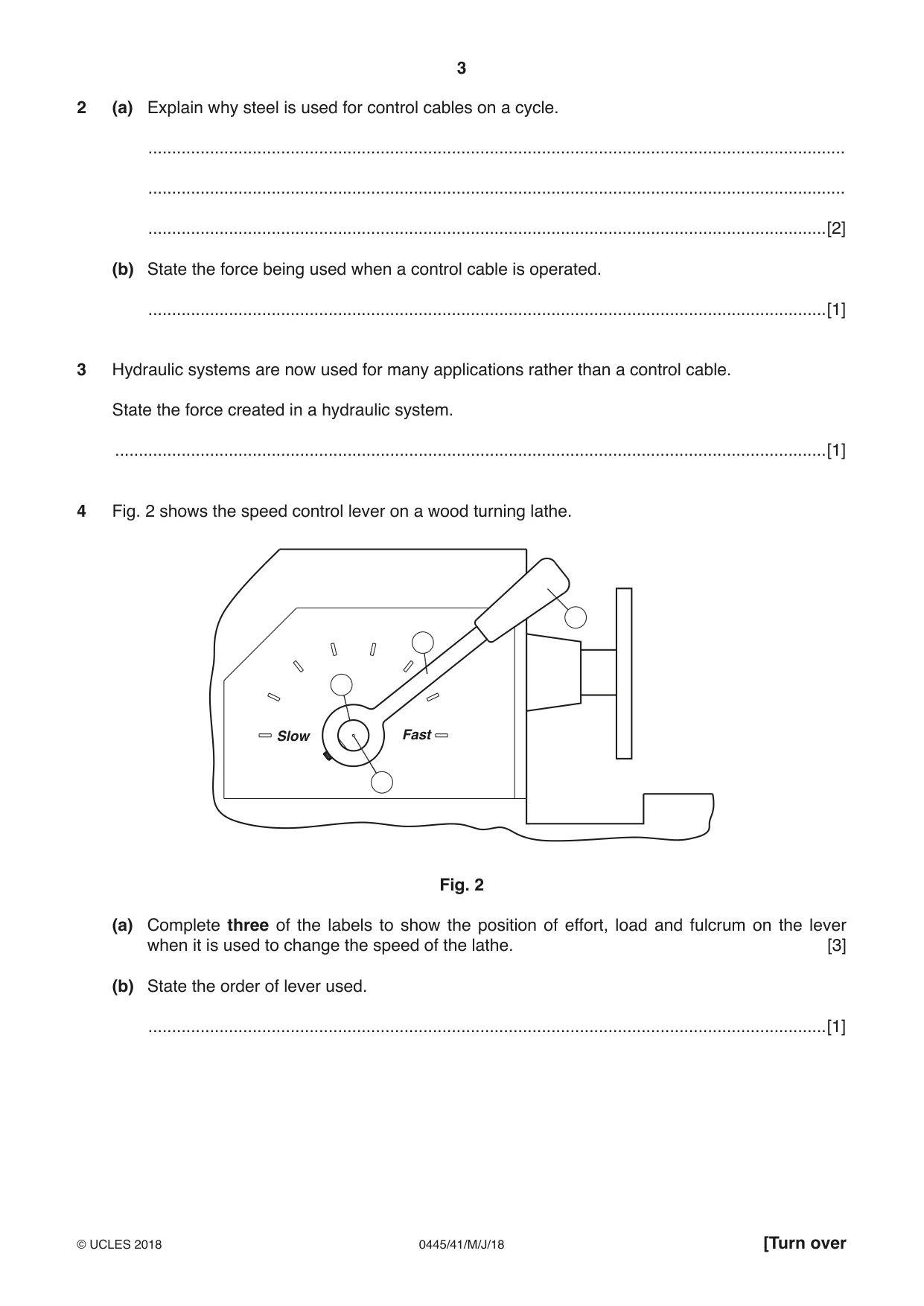
Q4 · The speed control lever on a wood turning lathe
4 Fig. 2 shows the speed control lever on a wood turning lathe. Slow Fast Fig. 2 (a) Complete three of the labels to show the position of effort, load and fulcrum on the lever when it is used to change the speed of the lathe. [3] (b) State the order of lever used. ...............................................................................................................................................[1]
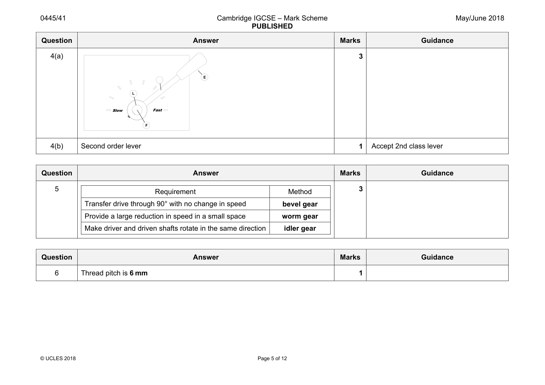
Mark scheme: 4(a) 3 4(b) Second order lever 1 Accept 2nd class lever Fast Slow L F E
Q5 · Choose from the terms below to complete the table
5 Choose from the terms below to complete the table. bevel gear idler gear rack and pinion worm gear Requirement Method Transfer drive through 90° with no change in speed Provide a large reduction in speed in a small space Make driver and driven shafts rotate in the same direction [3]
Mark scheme: 5 Requirement Method Transfer drive through 90° with no change in speed bevel gear Provide a large reduction in speed in a small space worm gear Make driver and driven shafts rotate in the same direction idler gear 3
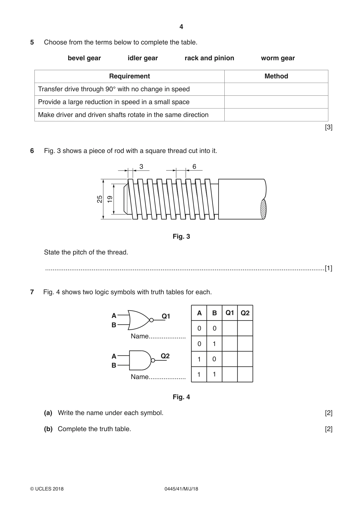
Q6 · A piece of rod with a square thread cut into it
6 Fig. 3 shows a piece of rod with a square thread cut into it. 3 6 2519 Fig. 3 State the pitch of the thread. ......................................................................................................................................................[1]
Mark scheme: 6 Thread pitch is 6 mm 1
Q7 · Two logic symbols with truth tables for each
7 Fig. 4 shows two logic symbols with truth tables for each. A B Q1 Q2 A Q1 B 0 0 Name.................... 0 1 A Q2 1 0 B 1 1 Name.................... Fig. 4 (a) Write the name under each symbol. [2] (b) Complete the truth table. [2]
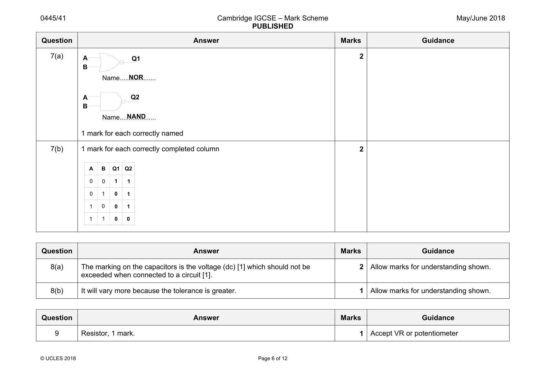
Mark scheme: 7(a) 1 mark for each correctly named 2 7(b) 1 mark for each correctly completed column 2 Q1 Q2 A B A B Name.................... Name.................... NOR NAND A B Q1 1 Q2 0 0 0 0 1 1 1 1 0 0 0 1 1 1 0
Q8 · A catalogue describes two capacitors in the following way: • electrolytic capacitor 3300…
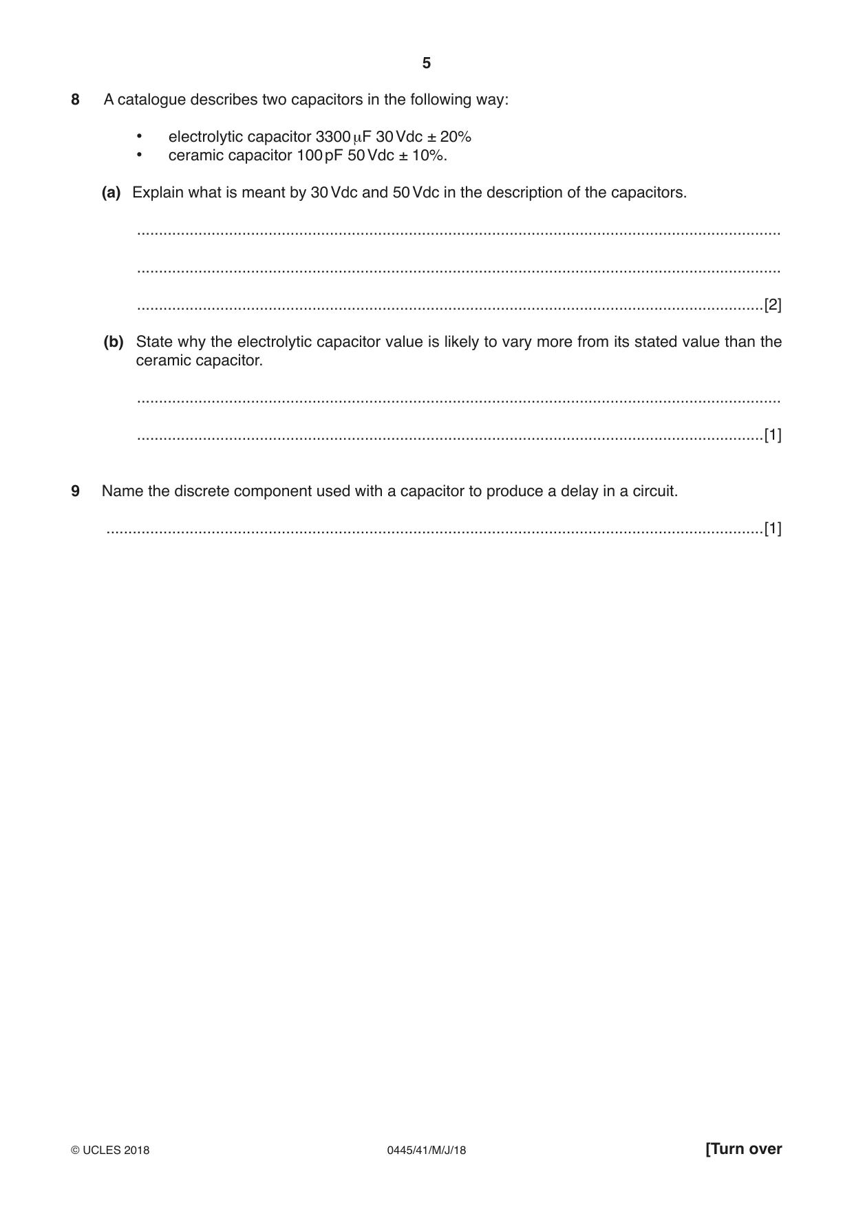
8 A catalogue describes two capacitors in the following way: • electrolytic capacitor 3300 μF 30 Vdc ± 20% • ceramic capacitor 100 pF 50 Vdc ± 10%. (a) Explain what is meant by 30 Vdc and 50 Vdc in the description of the capacitors. ................................................................................................................................................... ................................................................................................................................................... ...............................................................................................................................................[2] (b) State why the electrolytic capacitor value is likely to vary more from its stated value than the ceramic capacitor. ................................................................................................................................................... ...............................................................................................................................................[1]
Mark scheme: 8(a) The marking on the capacitors is the voltage (dc) [1] which should not be exceeded when connected to a circuit [1]. 2 Allow marks for understanding shown. 8(b) It will vary more because the tolerance is greater. 1 Allow marks for understanding shown.
Q9 · Name the discrete component used with a capacitor to produce a delay in a circuit
9 Name the discrete component used with a capacitor to produce a delay in a circuit. ......................................................................................................................................................[1]
Mark scheme: 9 Resistor, 1 mark. 1 Accept VR or potentiometer
Q10 · The initial design for a scaffold to give safe access while building work is carried out
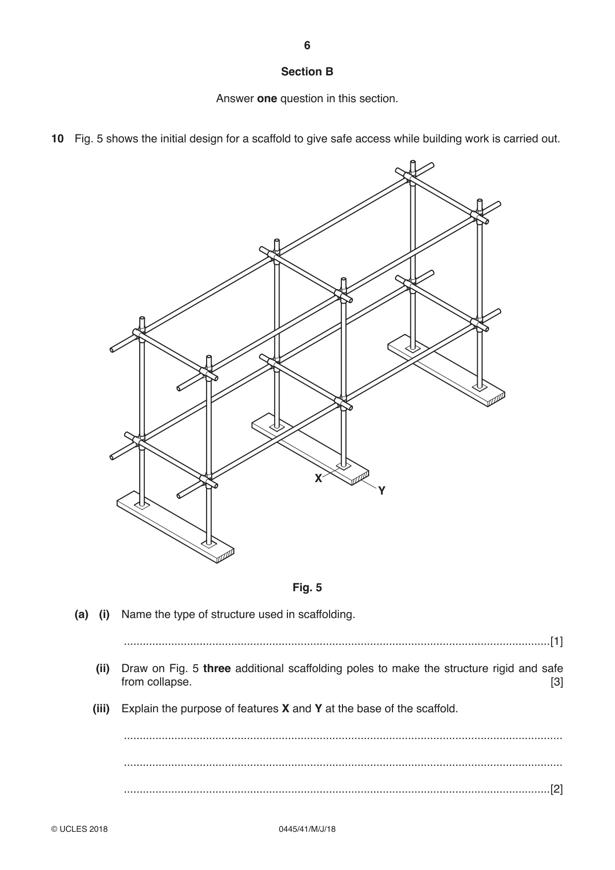
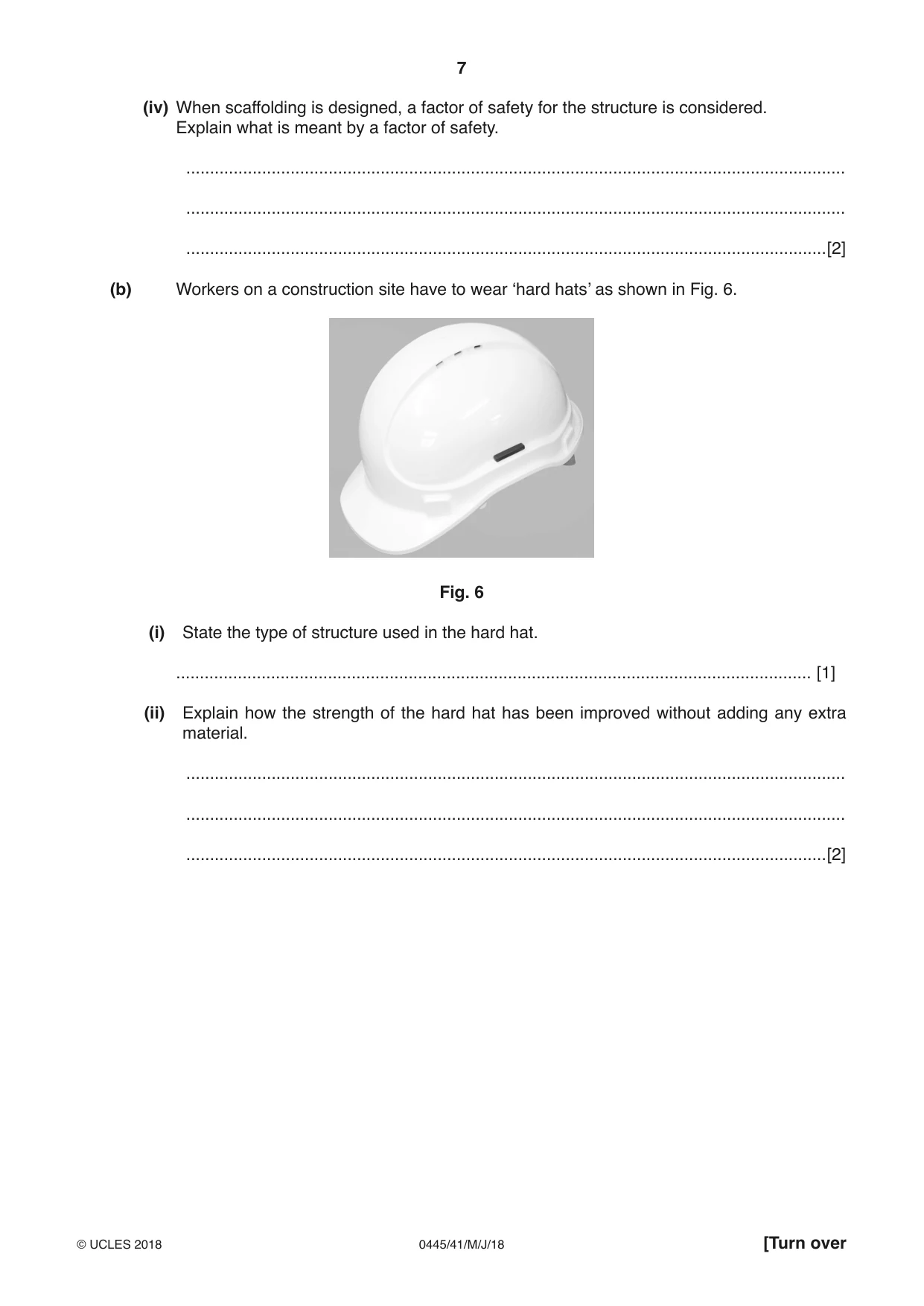
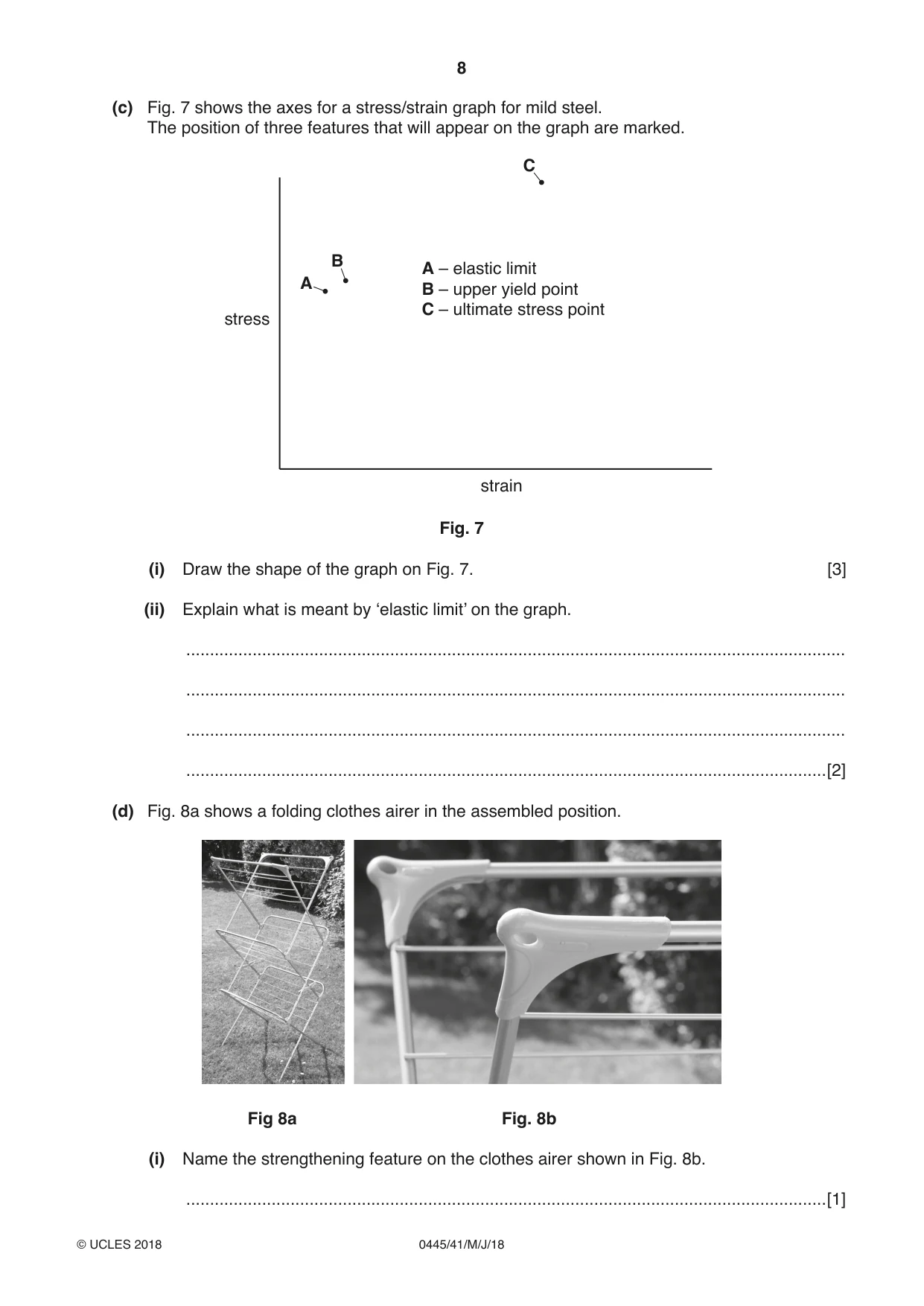
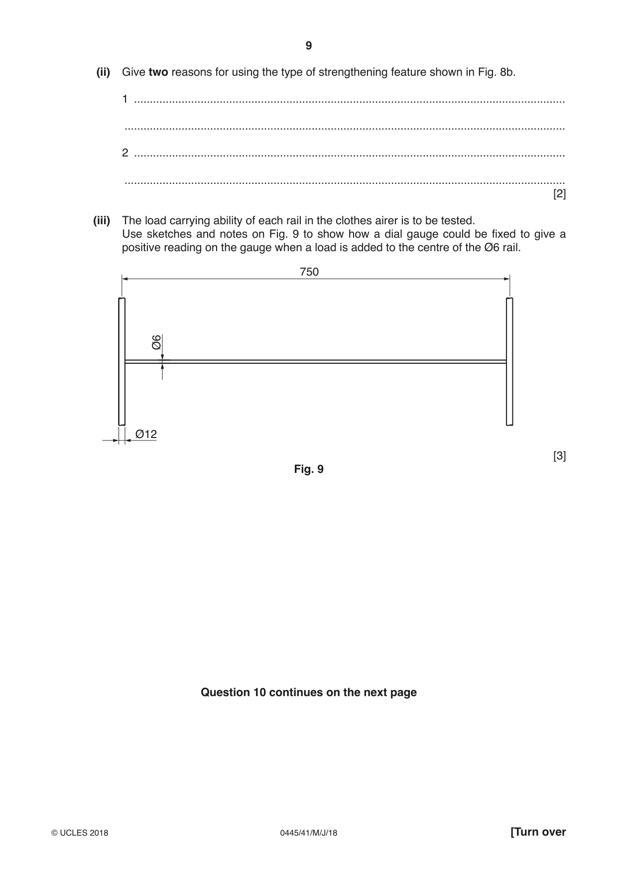
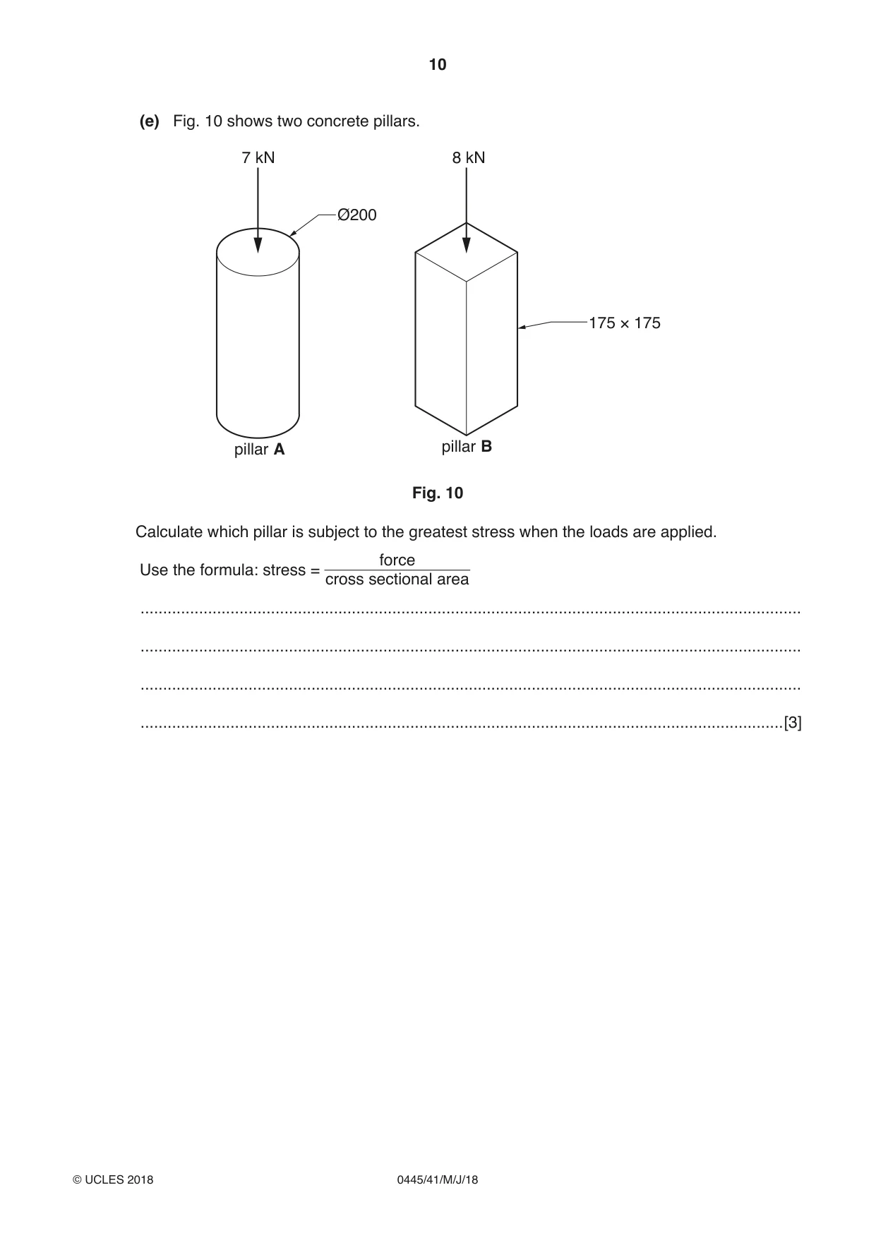
10 Fig. 5 shows the initial design for a scaffold to give safe access while building work is carried out. X Y Fig. 5 (a) (i) Name the type of structure used in scaffolding. .......................................................................................................................................[1] (ii) Draw on Fig. 5 three additional scaffolding poles to make the structure rigid and safe from collapse. [3] (iii) Explain the purpose of features X and Y at the base of the scaffold. ........................................................................................................................................... ........................................................................................................................................... .......................................................................................................................................[2] (iv) When scaffolding is designed, a factor of safety for the structure is considered. Explain what is meant by a factor of safety. ........................................................................................................................................... ........................................................................................................................................... .......................................................................................................................................[2] (b) Workers on a construction site have to wear ‘hard hats’ as shown in Fig. 6. Fig. 6 (i) State the type of structure used in the hard hat. ...................................................................................................................................... [1] (ii) Explain how the strength of the hard hat has been improved without adding any extra material. ........................................................................................................................................... ........................................................................................................................................... .......................................................................................................................................[2] (c) Fig. 7 shows the axes for a stress/strain graph for mild steel. The position of three features that will appear on the graph are marked. C B A – elastic limit A B – upper yield point C – ultimate stress point stress strain Fig. 7 (i) Draw the shape of the graph on Fig. 7. [3] (ii) Explain what is meant by ‘elastic limit’ on the graph. ........................................................................................................................................... ........................................................................................................................................... ........................................................................................................................................... .......................................................................................................................................[2] (d) Fig. 8a shows a folding clothes airer in the assembled position. Fig 8a Fig. 8b (i) Name the strengthening feature on the clothes airer shown in Fig. 8b. .......................................................................................................................................[1] (ii) Give two reasons for using the type of strengthening feature shown in Fig. 8b. 1 ........................................................................................................................................ ........................................................................................................................................... 2 ........................................................................................................................................ ........................................................................................................................................... [2] (iii) The load carrying ability of each rail in the clothes airer is to be tested. Use sketches and notes on Fig. 9 to show how a dial gauge could be fixed to give a positive reading on the gauge when a load is added to the centre of the Ø6 rail. 750 Ø6 Ø12 [3] Fig. 9 Question 10 continues on the next page (e) Fig. 10 shows two concrete pillars. 7 kN 8 kN Ø200 175 × 175 pillar A pillar B Fig. 10 Calculate which pillar is subject to the greatest stress when the loads are applied. forceUse the formula: stress = cross sectional area ................................................................................................................................................... ................................................................................................................................................... ................................................................................................................................................... ...............................................................................................................................................[3]
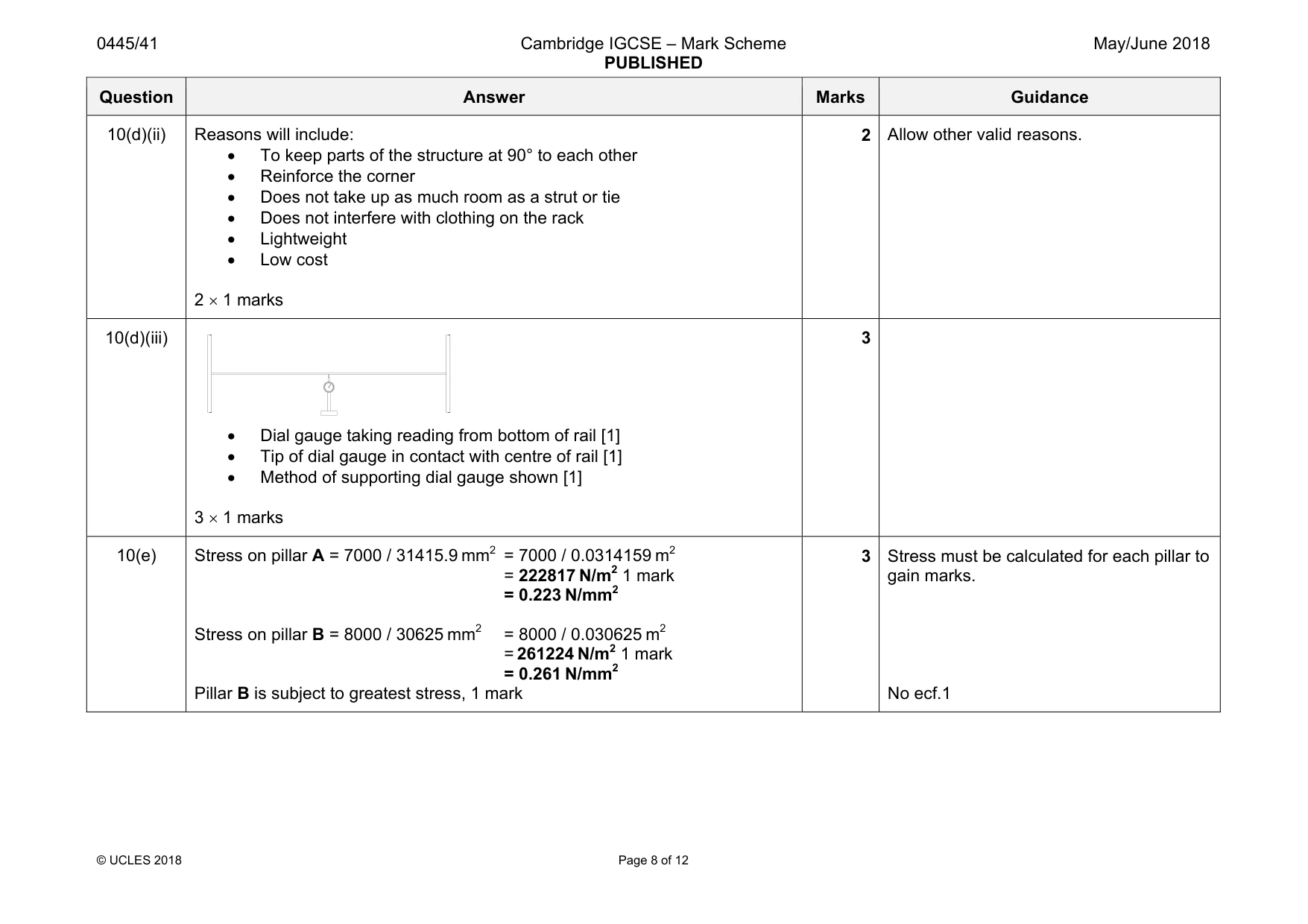
Mark scheme: 10(a)(i) Scaffolding is a frame structure 1 10(a)(ii) Each face of the structure to be made rigid, minimum of three poles. 1 mark for each pole in the correct position. 3 Maximum of 2 marks for multiple added poles in any one plane. 10(a)(iii) Features X and Y are to spread the load of the scaffold [1] and prevent it from sinking into soft ground. [1] They can also be used for levelling on uneven ground. [1] 2 1 mark each for any two correct points included. 10(a)(iv) A factor of safety is the load carrying capacity of a structure [1] beyond the expected loads. [1] The factor of safety is a number that is multiplied by the total expected load giving a load that design of structure must carry. [1] 2 One mark for each valid point made, allow examples in the explanation. Allow 2 marks for one point fully explained. 10(b)(i) The hard hat is a shell structure 1 10(b)(ii) Ribs have been moulded into the shell [1] to make the structure more rigid / prevent any flexing [1]. 2 Both points needed for 2 marks. 10(c)(i) 3 Smooth rise to elastic limit A[1] Sharp dip after upper yield point B[1] Gradual fall after ultimate stress point C[1] 10(c)(ii) Material will stretch / elongate until this point. [1] Elastic limit is the point beyond which the material will not return to its original length and is permanently deformed. [1] Stress is directly proportional to strain up to the elastic limit. [1] 2 Two points needed for 2 marks. 10(d)(i) Gusset plate 1 A B C stress strain A - elastic limit B - upper yield point C - ultimate stress point Question Answer Marks Guidance 10(d)(ii) Reasons will include: • To keep parts of the structure at 90° to each other • Reinforce the corner • Does not take up as much room as a strut or tie • Does not interfere with clothing on the rack • Lightweight • Low cost 2 × 1 marks 2 Allow other valid reasons. 10(d)(iii) • Dial gauge taking reading from bottom of rail [1] • Tip of dial gauge in contact with centre of rail [1] • Method of supporting dial gauge shown [1] 3 × 1 marks 3 10(e) Stress on pillar A = 7000 / 31415.9 mm2 = 7000 / 0.0314159 m2 = 222817 N/m2 1 mark = 0.223 N/mm2 Stress on pillar B = 8000 / 30625 mm2 = 8000 / 0.030625 m2 = 261224 N/m2 1 mark = 0.261 N/mm2 Pillar B is subject to greatest stress, 1 mark 3 Stress must be calculated for each pillar to gain marks. No ecf.1
Q11 · Views of the chain drive on a cycle
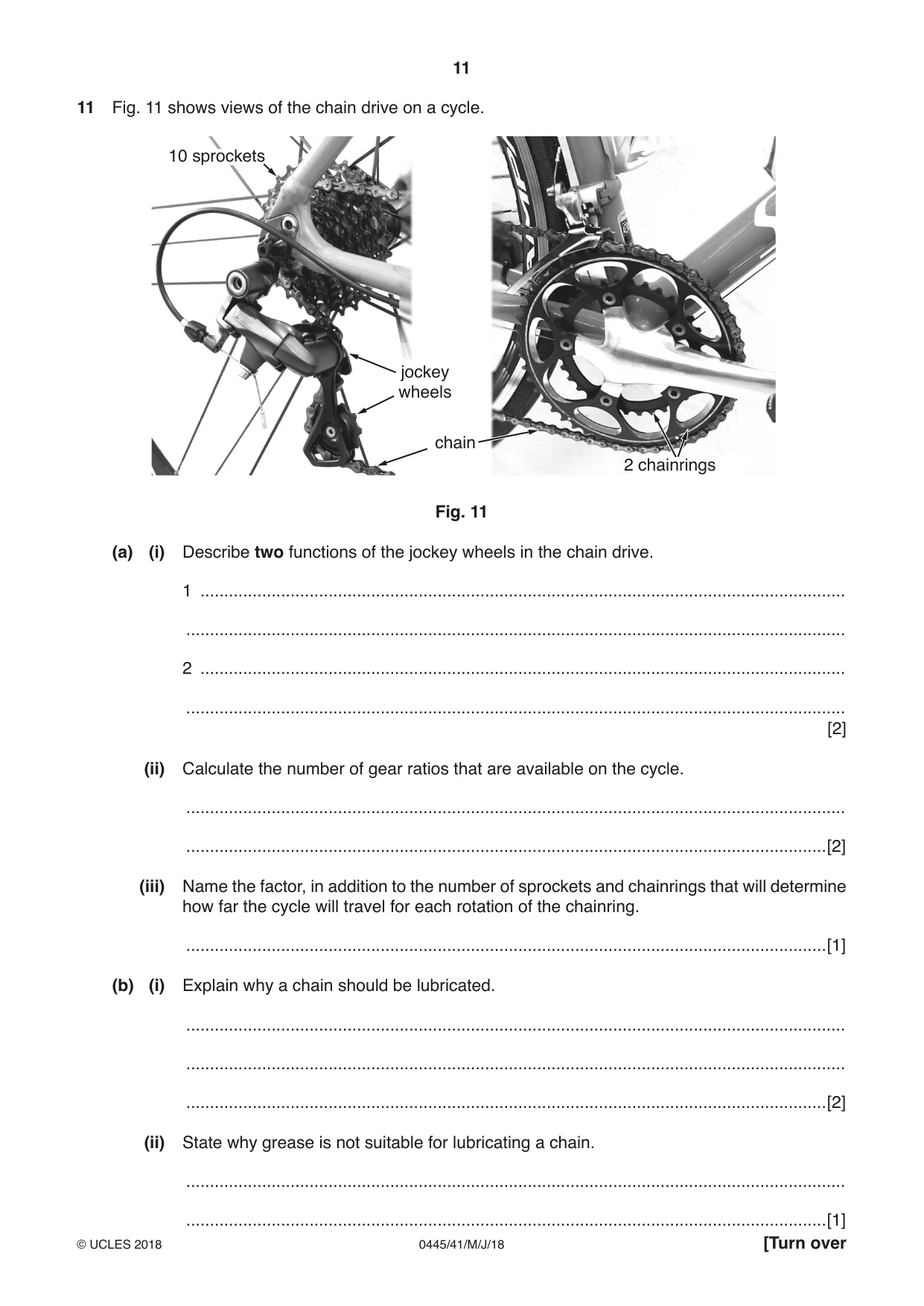
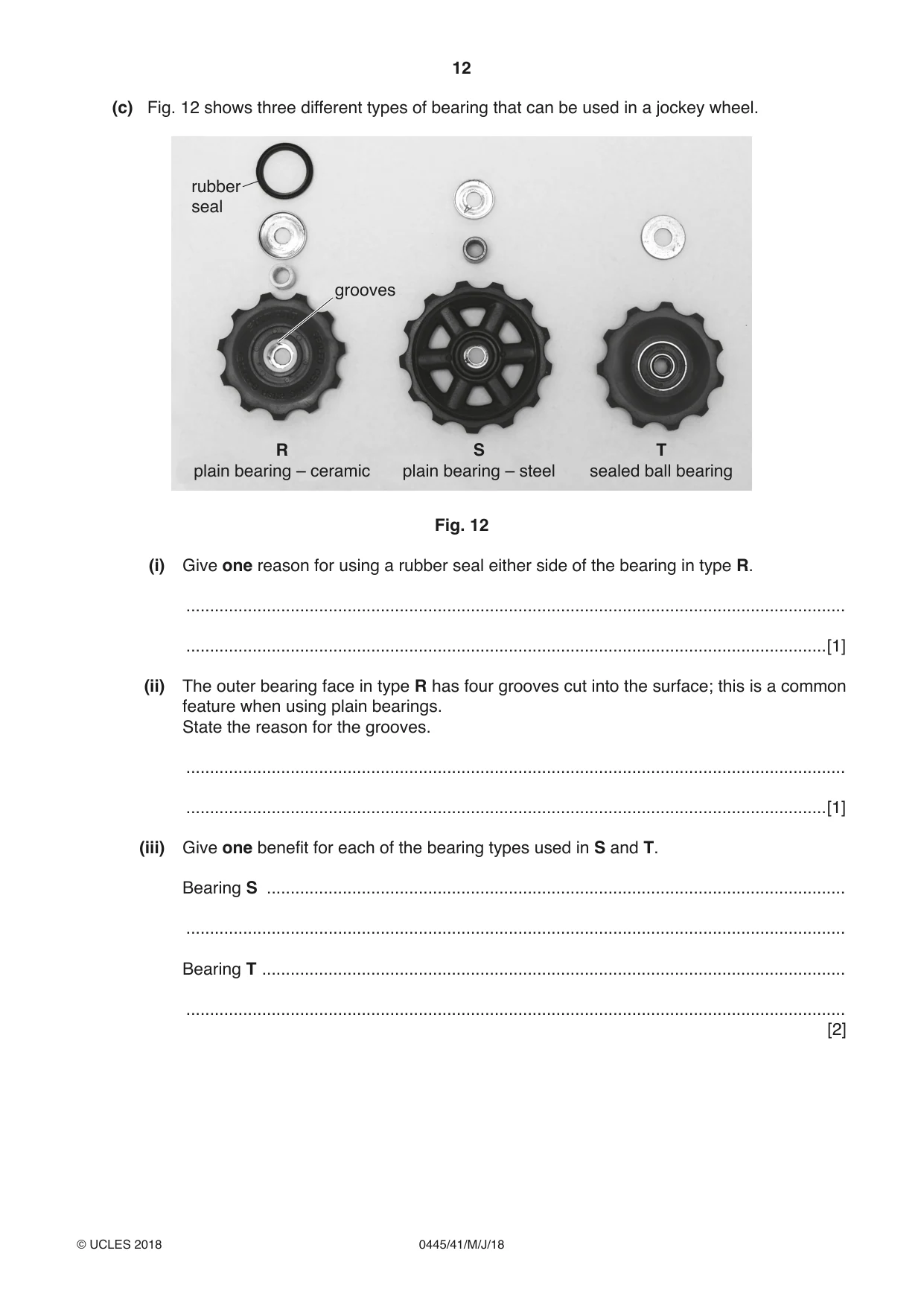
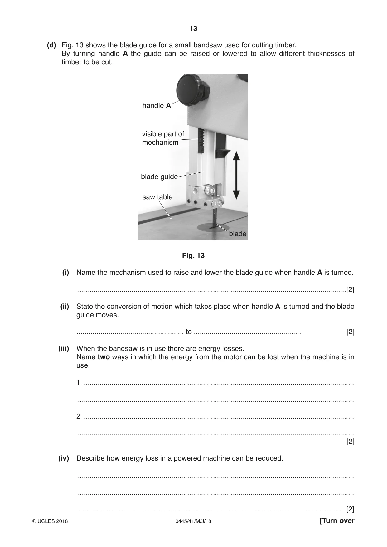
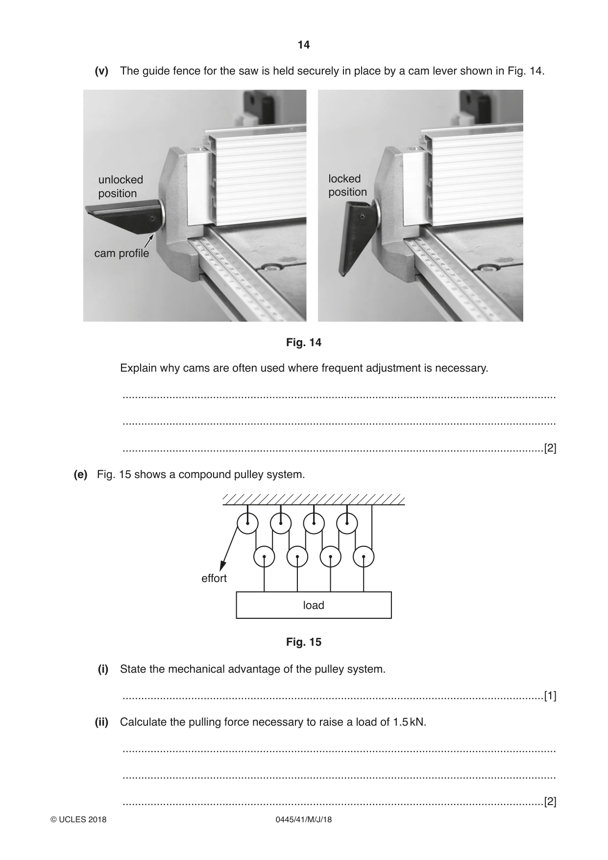
11 Fig. 11 shows views of the chain drive on a cycle. 10 sprockets jockey wheels chain 2 chainrings Fig. 11 (a) (i) Describe two functions of the jockey wheels in the chain drive. 1 ........................................................................................................................................ ........................................................................................................................................... 2 ........................................................................................................................................ ........................................................................................................................................... [2] (ii) Calculate the number of gear ratios that are available on the cycle. ........................................................................................................................................... .......................................................................................................................................[2] (iii) Name the factor, in addition to the number of sprockets and chainrings that will determine how far the cycle will travel for each rotation of the chainring. .......................................................................................................................................[1] (b) (i) Explain why a chain should be lubricated. ........................................................................................................................................... ........................................................................................................................................... .......................................................................................................................................[2] (ii) State why grease is not suitable for lubricating a chain. ........................................................................................................................................... (c) Fig. 12 shows three different types of bearing that can be used in a jockey wheel. rubber seal grooves R S T plain bearing – ceramic plain bearing – steel sealed ball bearing Fig. 12 (i) Give one reason for using a rubber seal either side of the bearing in type R. ........................................................................................................................................... .......................................................................................................................................[1] (ii) The outer bearing face in type R has four grooves cut into the surface; this is a common feature when using plain bearings. State the reason for the grooves. ........................................................................................................................................... .......................................................................................................................................[1] (iii) Give one benefit for each of the bearing types used in S and T. Bearing S .......................................................................................................................... ........................................................................................................................................... Bearing T ........................................................................................................................... ........................................................................................................................................... [2] (d) Fig. 13 shows the blade guide for a small bandsaw used for cutting timber. By turning handle A the guide can be raised or lowered to allow different thicknesses of timber to be cut. handle A visible part of mechanism blade guide saw table blade Fig. 13 (i) Name the mechanism used to raise and lower the blade guide when handle A is turned. .......................................................................................................................................[2] (ii) State the conversion of motion which takes place when handle A is turned and the blade guide moves. ...................................................... to ...................................................... [2] (iii) When the bandsaw is in use there are energy losses. Name two ways in which the energy from the motor can be lost when the machine is in use. 1 ........................................................................................................................................ ........................................................................................................................................... 2 ........................................................................................................................................ ........................................................................................................................................... [2] (iv) Describe how energy loss in a powered machine can be reduced. ........................................................................................................................................... ........................................................................................................................................... .......................................................................................................................................[2] (v) The guide fence for the saw is held securely in place by a cam lever shown in Fig. 14. unlocked locked position position cam profile Fig. 14 Explain why cams are often used where frequent adjustment is necessary. ........................................................................................................................................... ........................................................................................................................................... .......................................................................................................................................[2] (e) Fig. 15 shows a compound pulley system. effort load Fig. 15 (i) State the mechanical advantage of the pulley system. .......................................................................................................................................[1] (ii) Calculate the pulling force necessary to raise a load of 1.5 kN. ........................................................................................................................................... ........................................................................................................................................... .......................................................................................................................................[2]
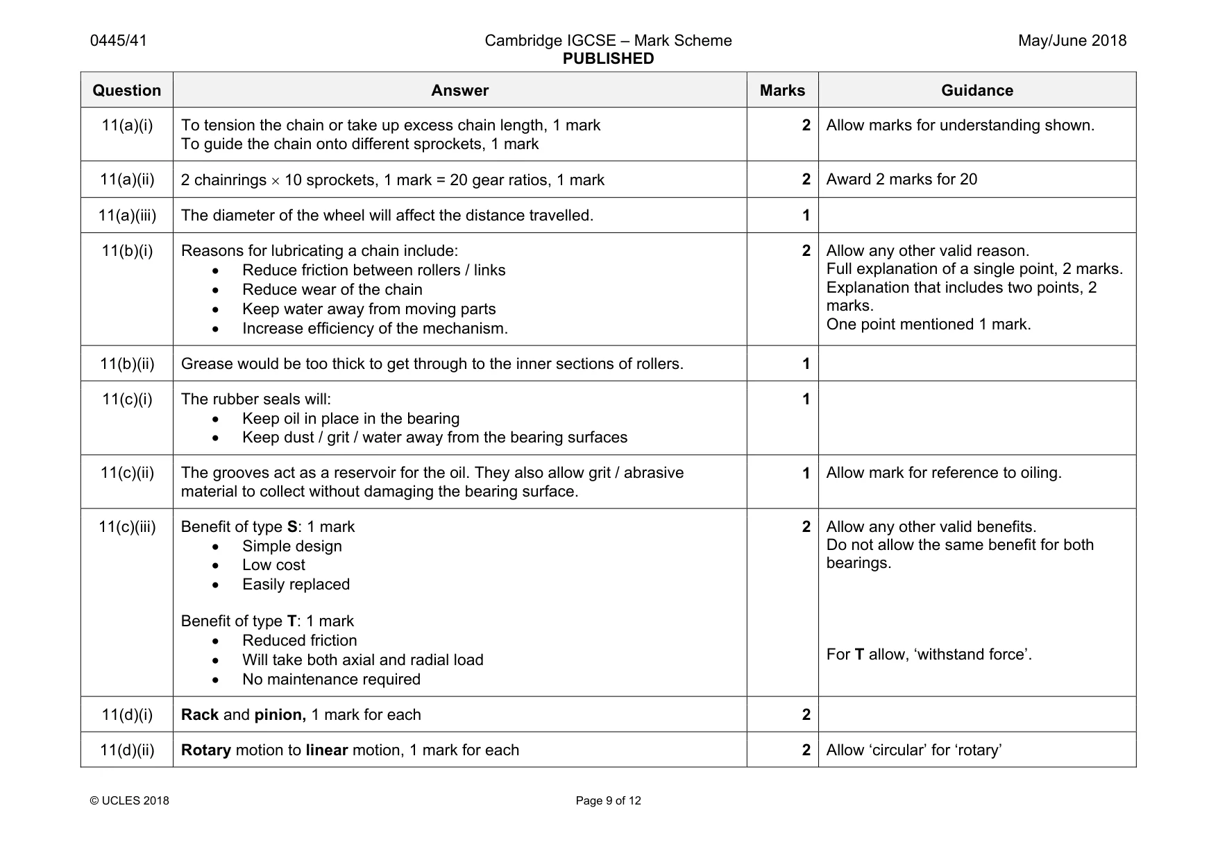
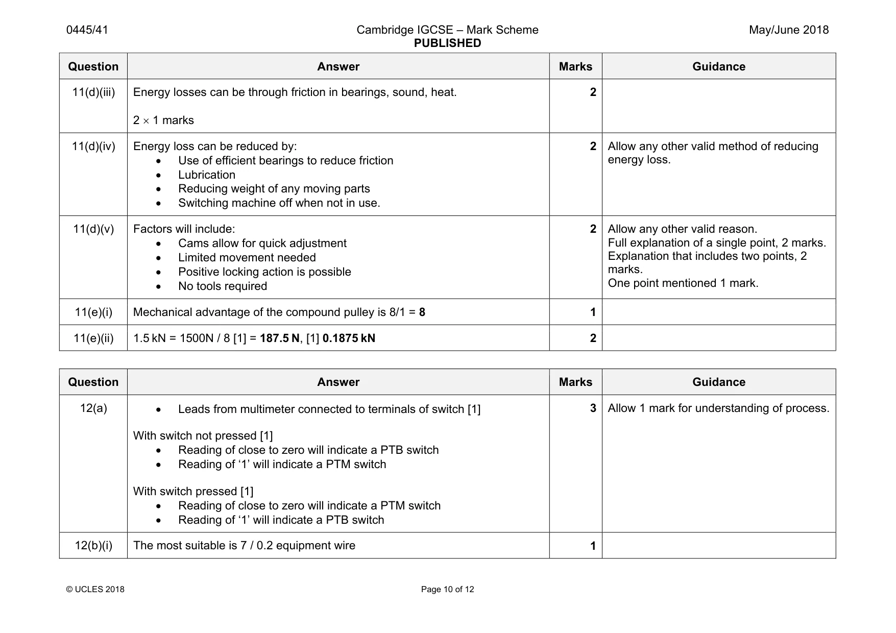
Mark scheme: 11(a)(i) To tension the chain or take up excess chain length, 1 mark To guide the chain onto different sprockets, 1 mark 2 11(a)(ii) 2 chainrings × 10 sprockets, 1 mark = 20 gear ratios, 1 mark 2 Award 2 marks for 20 11(a)(iii) The diameter of the wheel will affect the distance travelled. 1 11(b)(i) Reasons for lubricating a chain include: • Reduce friction between rollers / links • Reduce wear of the chain • Keep water away from moving parts • Increase efficiency of the mechanism. 2 Allow any other valid reason. Full explanation of a single point, 2 marks. Explanation that includes two points, 2 marks. One point mentioned 1 mark. 11(b)(ii) Grease would be too thick to get through to the inner sections of rollers. 1 11(c)(i) The rubber seals will: • Keep oil in place in the bearing • Keep dust / grit / water away from the bearing surfaces 1 11(c)(ii) The grooves act as a reservoir for the oil. They also allow grit / abrasive material to collect without damaging the bearing surface. 1 Allow mark for reference to oiling. 11(c)(iii) Benefit of type S: 1 mark • Simple design • Low cost • Easily replaced Benefit of type T: 1 mark • Reduced friction • Will take both axial and radial load • No maintenance required 2 Allow any other valid benefits. Do not allow the same benefit for both bearings. For T allow, ‘withstand force’. 11(d)(i) Rack and pinion, 1 mark for each 2 11(d)(ii) Rotary motion to linear motion, 1 mark for each 2 Allow ‘circular’ for ‘rotary’ Question Answer Marks Guidance 11(d)(iii) Energy losses can be through friction in bearings, sound, heat. 2 × 1 marks 2 11(d)(iv) Energy loss can be reduced by: • Use of efficient bearings to reduce friction • Lubrication • Reducing weight of any moving parts • Switching machine off when not in use. 2 Allow any other valid method of reducing energy loss. 11(d)(v) Factors will include: • Cams allow for quick adjustment • Limited movement needed • Positive locking action is possible • No tools required 2 Allow any other valid reason. Full explanation of a single point, 2 marks. Explanation that includes two points, 2 marks. One point mentioned 1 mark. 11(e)(i) Mechanical advantage of the compound pulley is 8/1 = 8 1 11(e)(ii) 1.5 kN = 1500N / 8 [1] = 187.5 N, [1] 0.1875 kN 2
Q12 · A push switch that could be either a PTM switch or a PTB switch, the two types are…
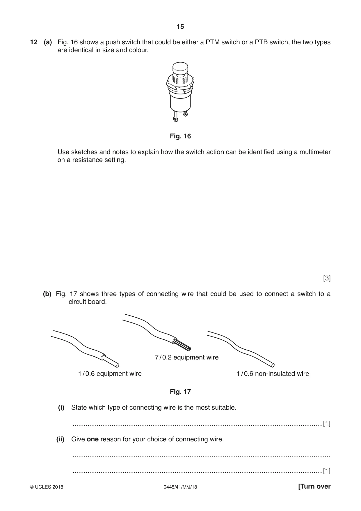
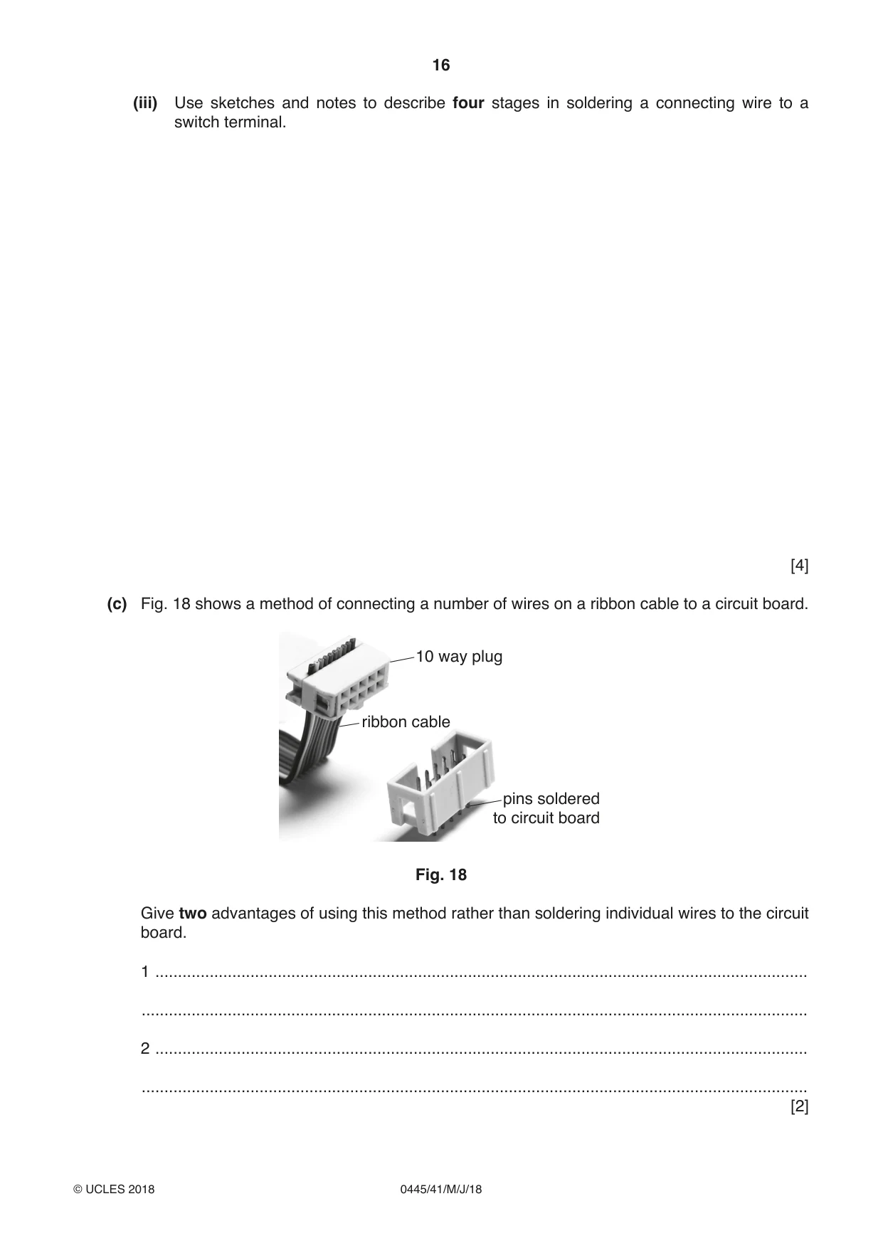
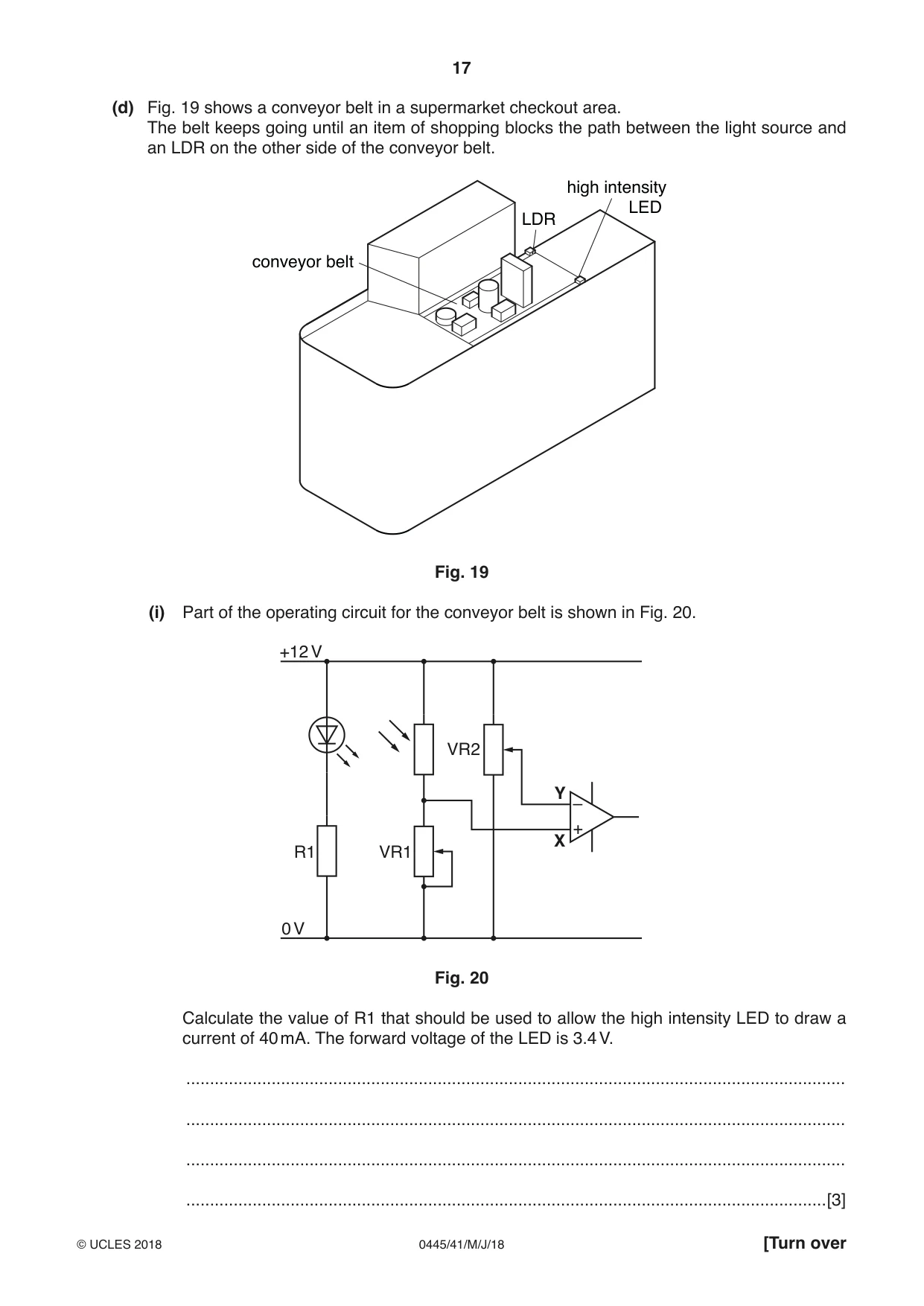
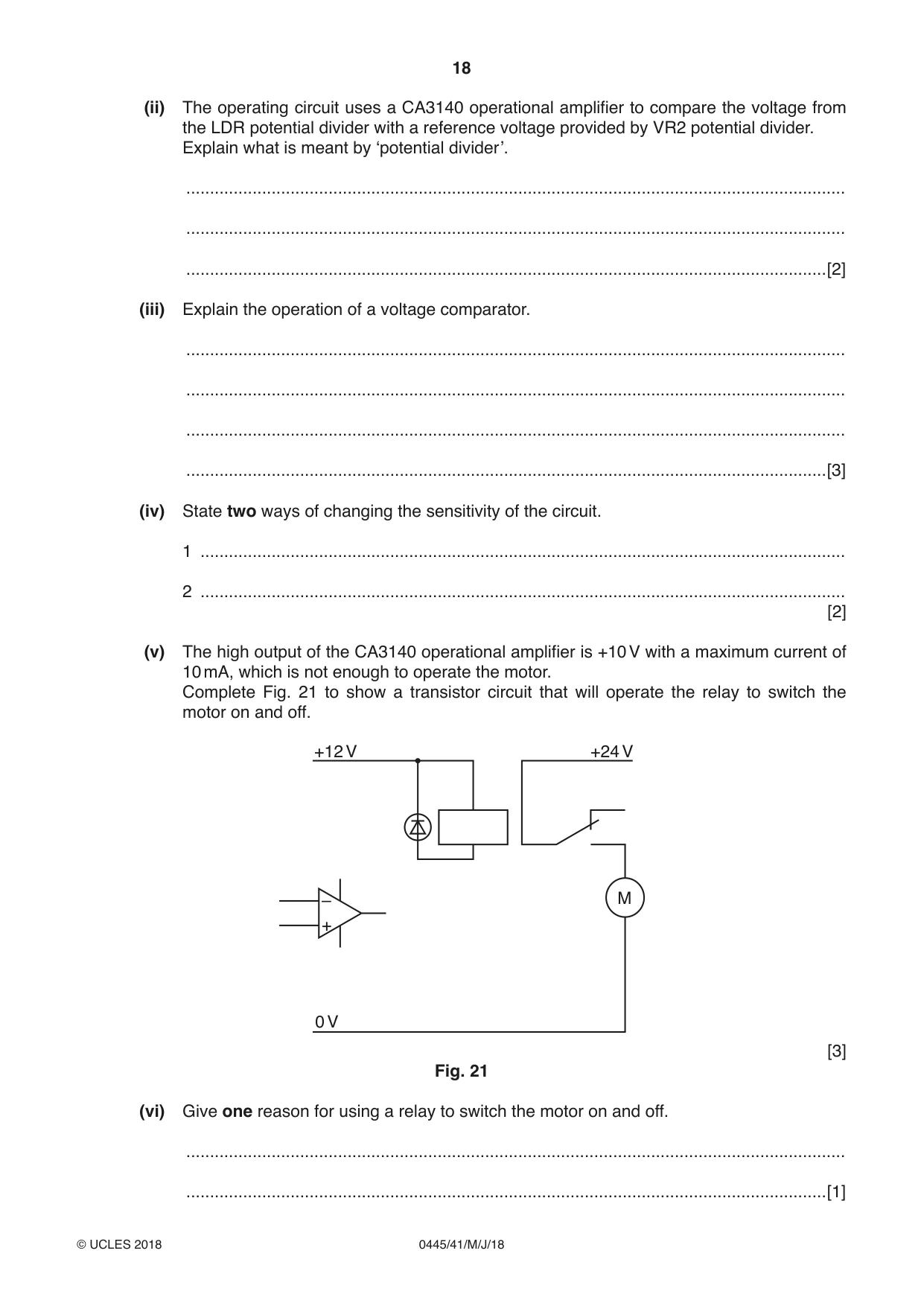
12 (a) Fig. 16 shows a push switch that could be either a PTM switch or a PTB switch, the two types are identical in size and colour. Fig. 16 Use sketches and notes to explain how the switch action can be identified using a multimeter on a resistance setting. [3] (b) Fig. 17 shows three types of connecting wire that could be used to connect a switch to a circuit board. 7 / 0.2 equipment wire 1 / 0.6 equipment wire 1 / 0.6 non-insulated wire Fig. 17 (i) State which type of connecting wire is the most suitable. .......................................................................................................................................[1] (ii) Give one reason for your choice of connecting wire. ........................................................................................................................................... .......................................................................................................................................[1] (iii) Use sketches and notes to describe four stages in soldering a connecting wire to a switch terminal. [4] (c) Fig. 18 shows a method of connecting a number of wires on a ribbon cable to a circuit board. 10 way plug ribbon cable pins soldered to circuit board Fig. 18 Give two advantages of using this method rather than soldering individual wires to the circuit board. 1 ................................................................................................................................................ ................................................................................................................................................... 2 ................................................................................................................................................ ................................................................................................................................................... [2] (d) Fig. 19 shows a conveyor belt in a supermarket checkout area. The belt keeps going until an item of shopping blocks the path between the light source and an LDR on the other side of the conveyor belt. high intensity LED LDR conveyor belt Fig. 19 (i) Part of the operating circuit for the conveyor belt is shown in Fig. 20. +12 V VR2 Y – + X R1 VR1 0 V Fig. 20 Calculate the value of R1 that should be used to allow the high intensity LED to draw a current of 40 mA. The forward voltage of the LED is 3.4 V. ........................................................................................................................................... ........................................................................................................................................... ........................................................................................................................................... .......................................................................................................................................[3]
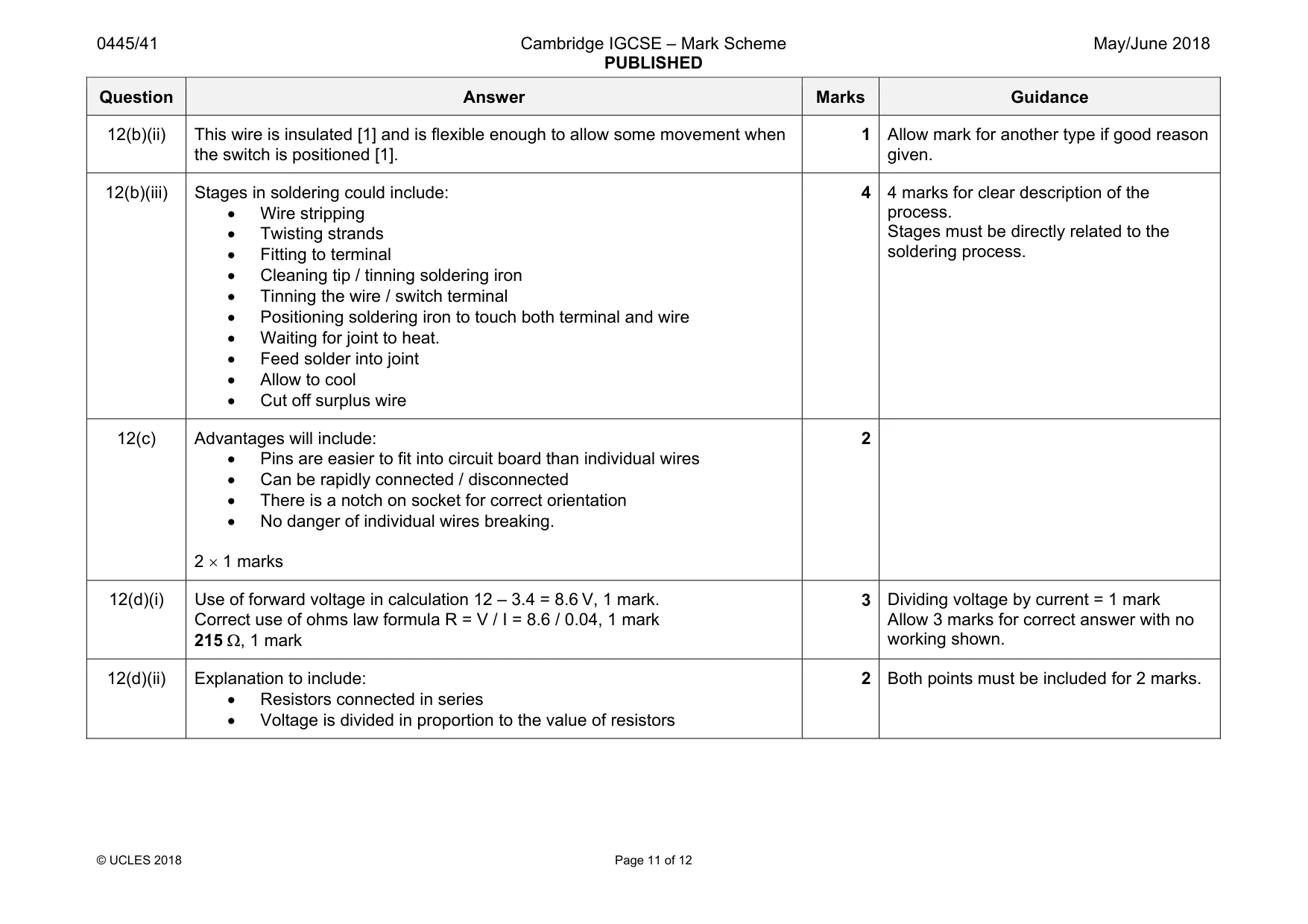
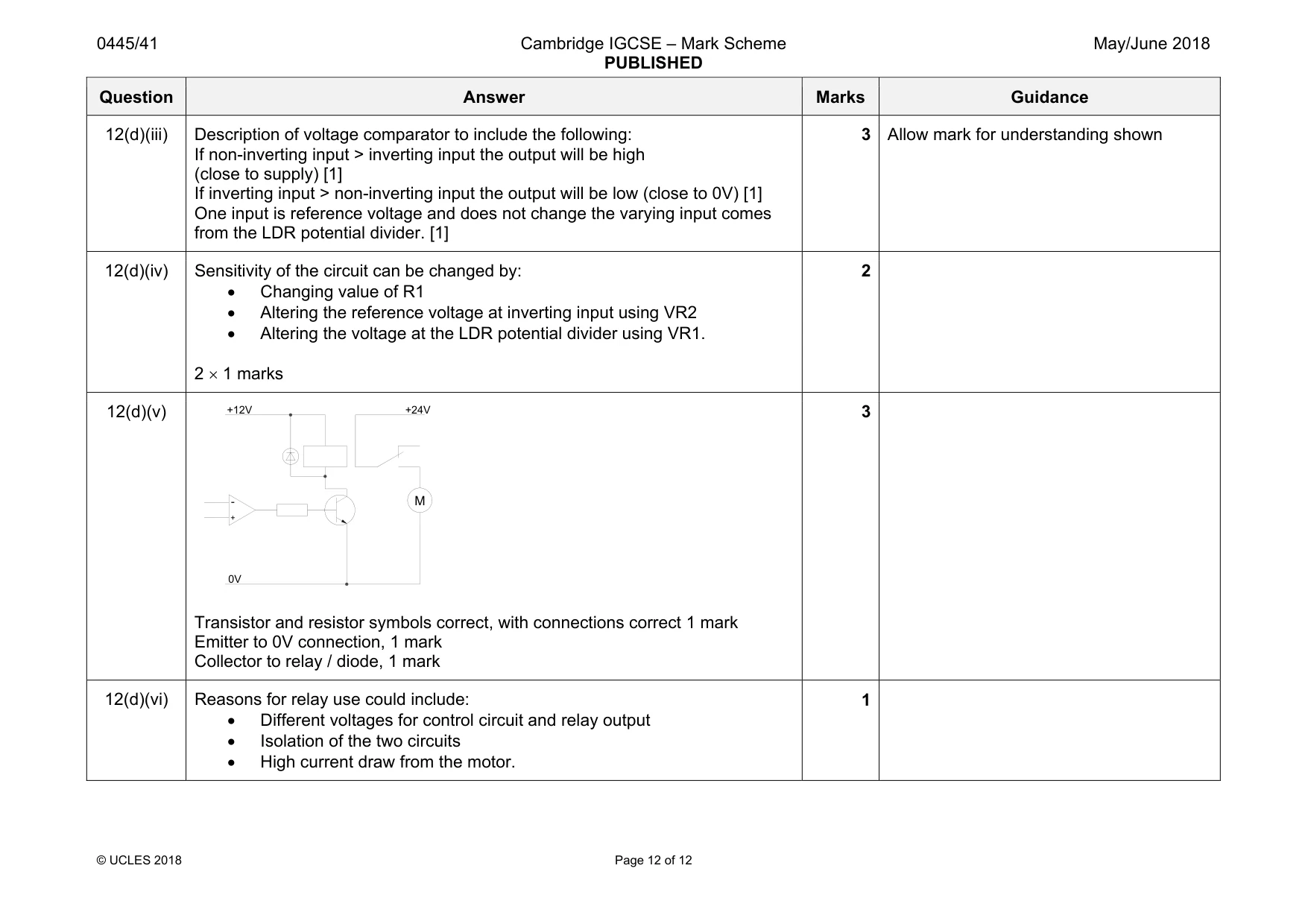
Mark scheme: 12(a) Leads from multimeter connected to terminals of switch [1] With switch not pressed [1] • Reading of close to zero will indicate a PTB switch • Reading of ‘1’ will indicate a PTM switch With switch pressed [1] • Reading of close to zero will indicate a PTM switch • Reading of ‘1’ will indicate a PTB switch 3 12(b)(i) The most suitable is 7 / 0.2 equipment wire 1 Question Answer Marks Guidance 12(b)(ii) This wire is insulated [1] and is flexible enough to allow some movement when the switch is positioned [1]. 1 Allow mark for another type if good reason given. 12(b)(iii) Stages in soldering could include: • Wire stripping • Twisting strands • Fitting to terminal • Cleaning tip / tinning soldering iron • Tinning the wire / switch terminal • Positioning soldering iron to touch both terminal and wire • Waiting for joint to heat. • Feed solder into joint • Allow to cool • Cut off surplus wire 4 4 marks for clear description of the process. Stages must be directly related to the soldering process. 12(c) Advantages will include: • Pins are easier to fit into circuit board than individual wires • Can be rapidly connected / disconnected • There is a notch on socket for correct orientation • No danger of individual wires breaking. 2 × 1 marks 2 12(d)(i) Use of forward voltage in calculation 12 – 3.4 = 8.6 V, 1 mark. Correct use of ohms law formula R = V / I = 8.6 / 0.04, 1 mark 215 Ω, 1 mark 3 Dividing voltage by current = 1 mark Allow 3 marks for correct answer with no working shown. 12(d)(ii) Explanation to include: • Resistors connected in series • Voltage is divided in proportion to the value of resistors 2 Both points must be included for 2 marks. Question Answer Marks Guidance 12(d)(iii) Description of voltage comparator to include the following: If non-inverting input > inverting input the output will be high (close to supply) [1] If inverting input > non-inverting input the output will be low (close to 0V) [1] One input is reference voltage and does not change the varying input comes from the LDR potential divider. [1] 3 Allow mark for understanding shown 12(d)(iv) Sensitivity of the circuit can be changed by: • Changing value of R1 • Altering the reference voltage at inverting input using VR2 • Altering the voltage at the LDR potential divider using VR1. 2 × 1 marks 2 12(d)(v) Transistor and resistor symbols correct, with connections correct 1 mark Emitter to 0V connection, 1 mark Collector to relay / diode, 1 mark 3 12(d)(vi) Reasons for relay use could include: • Different voltages for control circuit and relay output • Isolation of the two circuits • High current draw from the motor. 1 M +12V 0V +24V
What was in this paper
The subtopics covered by these 12 questions, and how many questions each got. Open one in a new tab to see every Cambridge question on it.
What you needed in this session
Cambridge’s own grade thresholds for 2018 May/June, Paper 4 · Variant 1. A higher threshold means an easier paper — the bar moves with how the cohort did.