Cambridge IGCSE Design and Technology 0445 — 2017 Oct/Nov Paper 4 · Variant 1
0445/41/O/N/17 · 12 questions · 50 marks · ≈56 min
The question paper and its mark scheme, free to read here and free to download. This is Cambridge’s own paper, exactly as it was sat.
Question paper20 pages


Mark scheme11 pages
Answers below. Sit the paper first if you are practising.
Questions as text
Q1 · Three switches and their circuit symbols
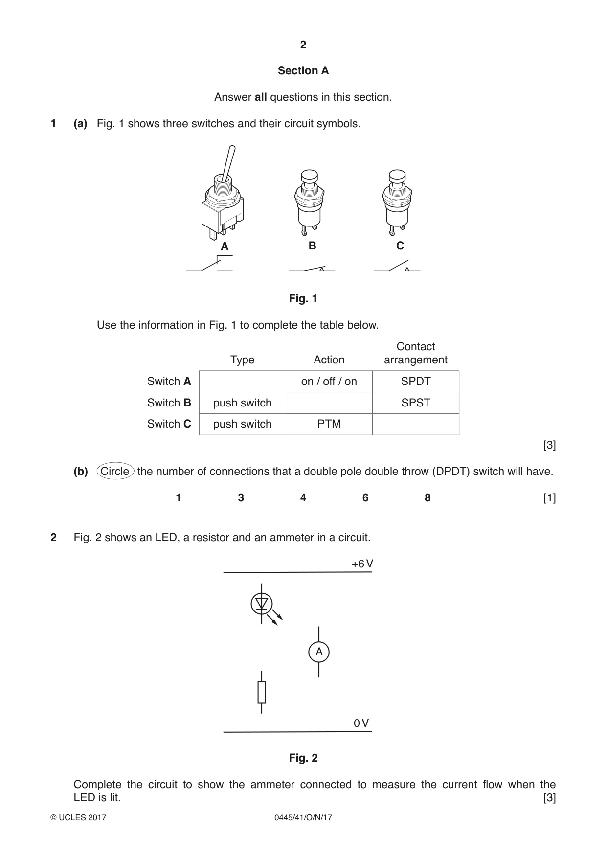
1 (a) Fig. 1 shows three switches and their circuit symbols. A B C Fig. 1 Use the information in Fig. 1 to complete the table below. Contact Type Action arrangement Switch A on / off / on SPDT Switch B push switch SPST Switch C push switch PTM [3] (b) Circle the number of connections that a double pole double throw (DPDT) switch will have. 1 3 4 6 8 [1]
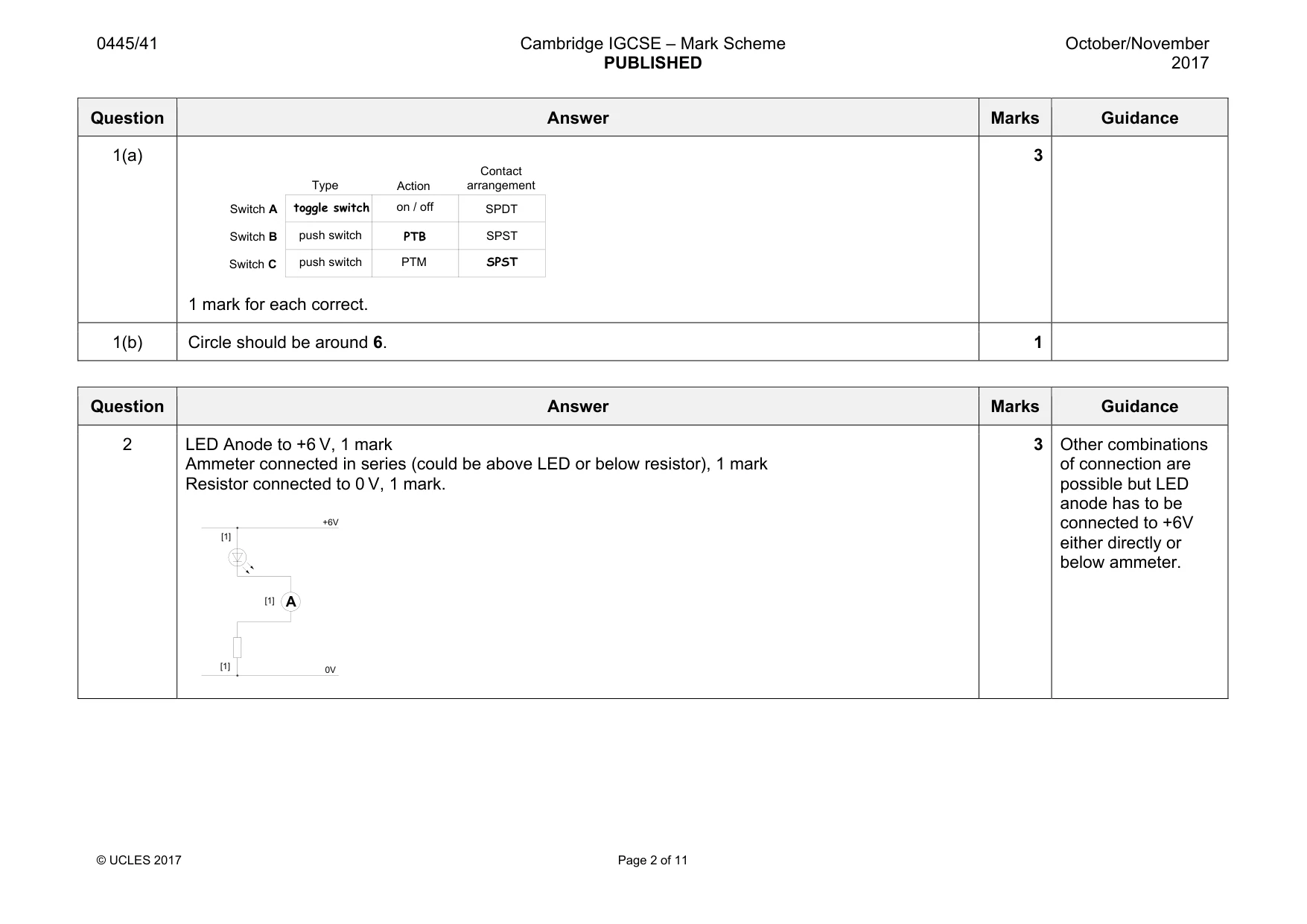
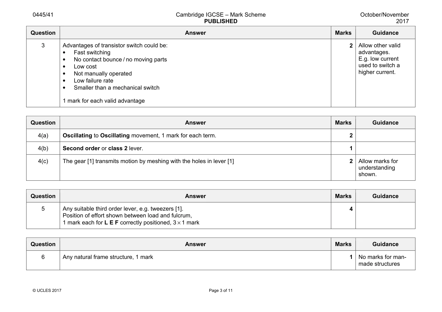
Mark scheme: 1(a) 1 mark for each correct. 3 1(b) Circle should be around 6. 1 Type Action Contact arrangement push switch SPST SPDT push switch on / off Switch A Switch B Switch C PTM toggle switch PTB SPST
Q2 · An LED, a resistor and an ammeter in a circuit
2 Fig. 2 shows an LED, a resistor and an ammeter in a circuit. +6 V A 0 V Fig. 2 Complete the circuit to show the ammeter connected to measure the current flow when the LED is lit. [3]
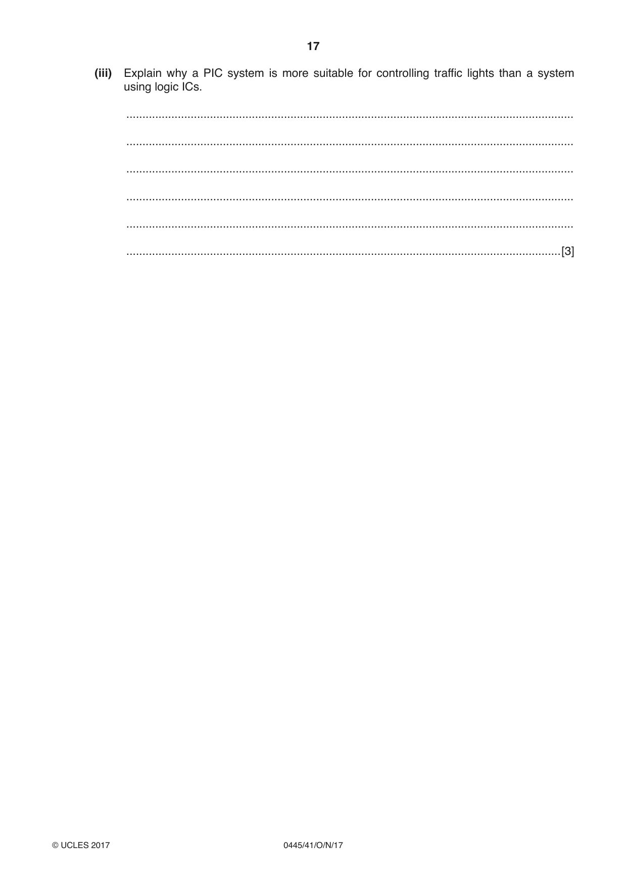
Mark scheme: A +6V 0V [1] [1] [1] 2 LED Anode to +6 V, 1 mark Ammeter connected in series (could be above LED or below resistor), 1 mark Resistor connected to 0 V, 1 mark. 3 of connection are possible but LED anode has to be connected to +6V either directly or below ammeter.
Q3 · A transistor can be used as an electronic switch
3 A transistor can be used as an electronic switch. Give two advantages of a transistor switch over a mechanical switch such as a push switch. 1 ....................................................................................................................................................... 2 ....................................................................................................................................................... [2]
Mark scheme: 3 Advantages of transistor switch could be: • Fast switching • No contact bounce / no moving parts • Low cost • Not manually operated • Low failure rate • Smaller than a mechanical switch 1 mark for each valid advantage 2 Allow other valid advantages. E.g. low current used to switch a higher current.
Q4 · An ice cream scoop that uses a moveable bar to release a ball of ice cream when the lever…
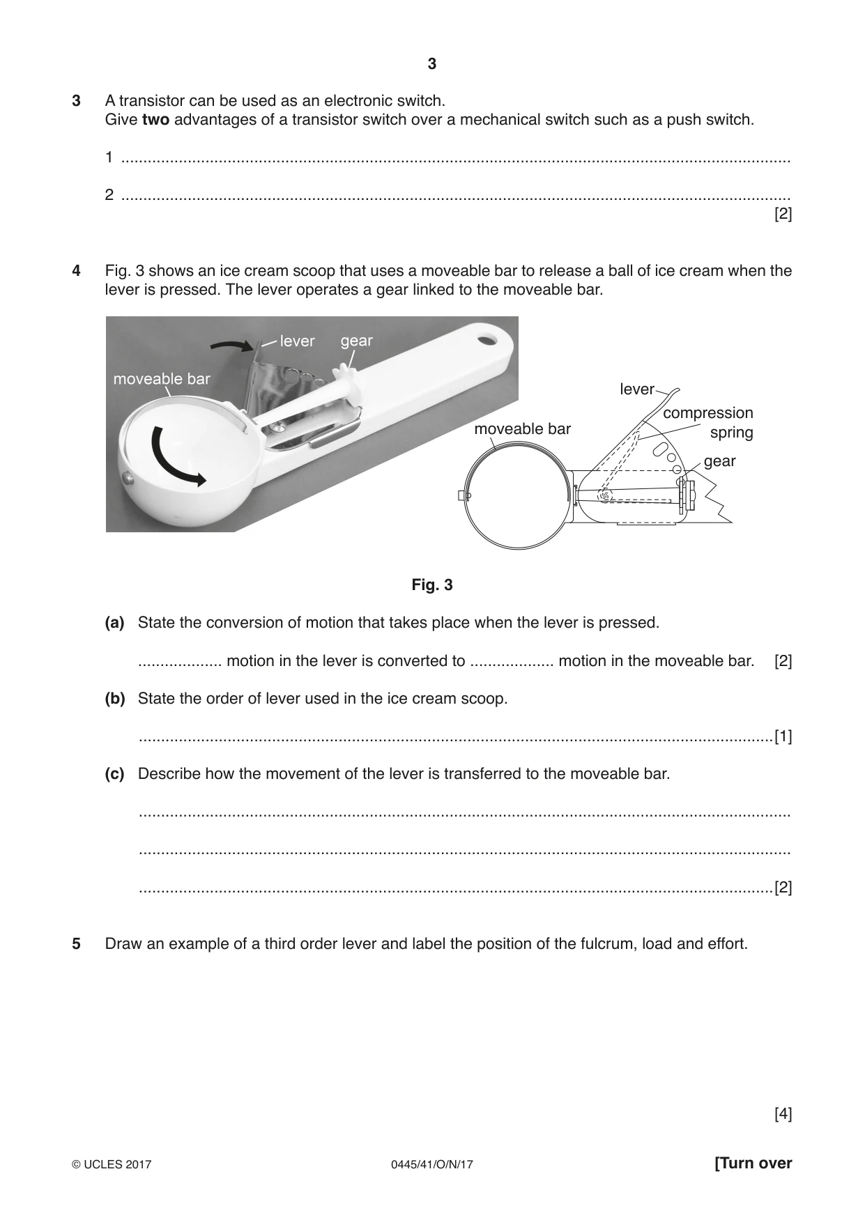
4 Fig. 3 shows an ice cream scoop that uses a moveable bar to release a ball of ice cream when the lever is pressed. The lever operates a gear linked to the moveable bar. lever compression moveable bar spring gear Fig. 3 (a) State the conversion of motion that takes place when the lever is pressed. ................... motion in the lever is converted to ................... motion in the moveable bar. [2] (b) State the order of lever used in the ice cream scoop. ...............................................................................................................................................[1] (c) Describe how the movement of the lever is transferred to the moveable bar. ................................................................................................................................................... ................................................................................................................................................... ...............................................................................................................................................[2]
Mark scheme: 4(a) Oscillating to Oscillating movement, 1 mark for each term. 2 4(b) Second order or class 2 lever. 1 4(c) The gear [1] transmits motion by meshing with the holes in lever [1] 2 Allow marks for understanding shown.
Q5 · Draw an example of a third order lever and label the position of the fulcrum, load and…
5 Draw an example of a third order lever and label the position of the fulcrum, load and effort. [4]
Mark scheme: 5 Any suitable third order lever, e.g. tweezers [1]. Position of effort shown between load and fulcrum, 1 mark each for L E F correctly positioned, 3 × 1 mark 4
Q6 · Draw and name a natural frame structure
6 Draw and name a natural frame structure. [1]
Mark scheme: 6 Any natural frame structure, 1 mark 1 No marks for man- made structures
Q7 · Draw and name a natural shell structure
7 Draw and name a natural shell structure. [1]
Mark scheme: 7 Any natural shell structure, 1 mark 1 No marks for man- made structures
Q8 · A bracket made from square steel tube
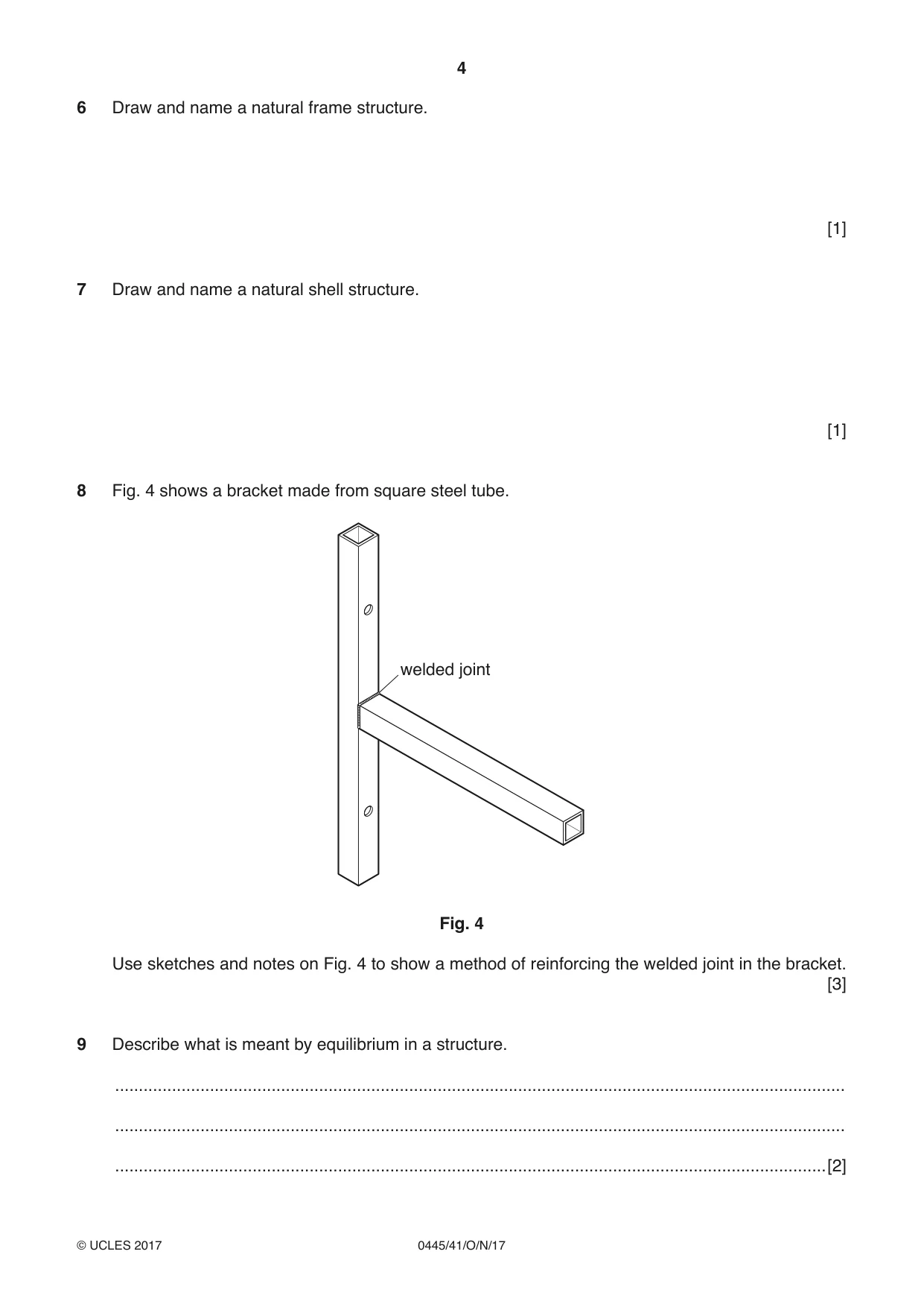
8 Fig. 4 shows a bracket made from square steel tube. welded joint Fig. 4 Use sketches and notes on Fig. 4 to show a method of reinforcing the welded joint in the bracket. [3]
Mark scheme: 8 Gusset, brace or tie used 1 mark. Correct position, e.g. tie used above joint, brace below joint, gusset either above or below joint, 1 mark. Clear sketches / notes to show fixing method / how the reinforcement would work, 1 mark. 3
Q9 · Describe what is meant by equilibrium in a structure
9 Describe what is meant by equilibrium in a structure. .......................................................................................................................................................... .......................................................................................................................................................... ......................................................................................................................................................[2]
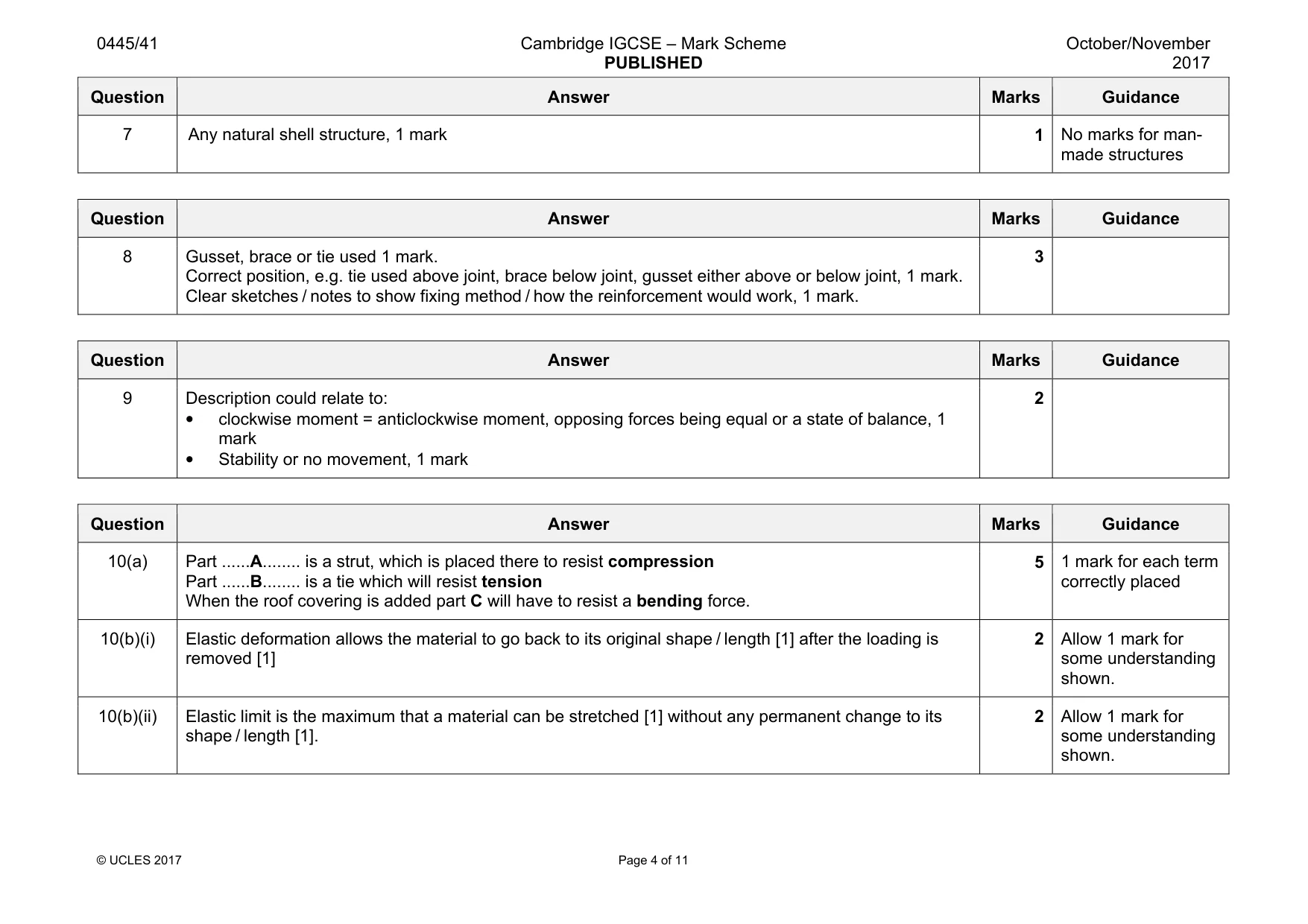
Mark scheme: 9 Description could relate to: • clockwise moment = anticlockwise moment, opposing forces being equal or a state of balance, 1 mark • Stability or no movement, 1 mark 2
Question 10
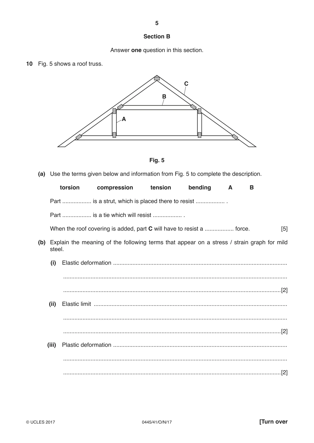
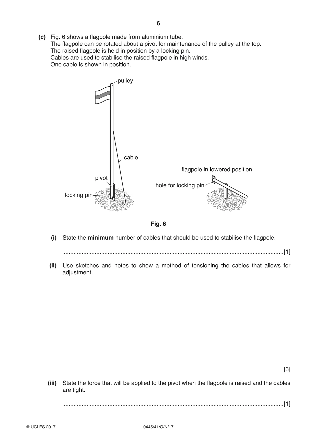
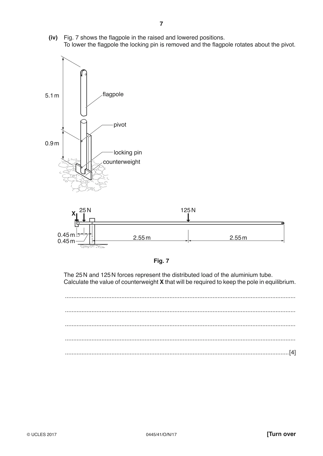
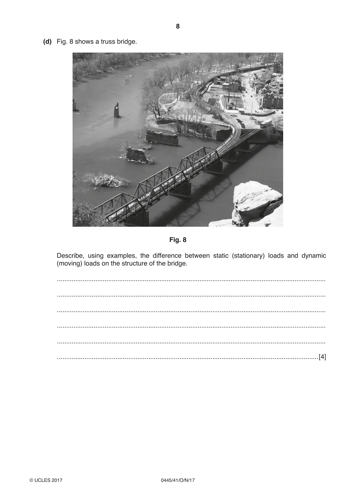
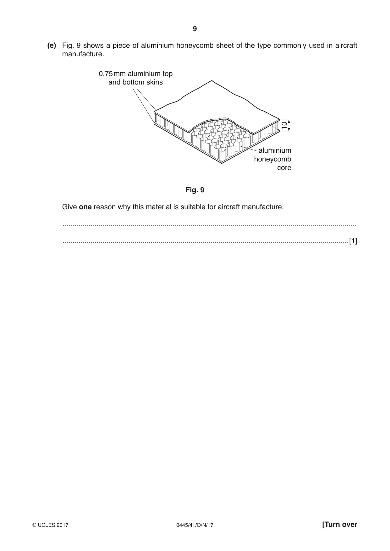
10 Fig. 5 shows a roof truss. C B A Fig. 5 (a) Use the terms given below and information from Fig. 5 to complete the description. torsion compression tension bending A B Part .................. is a strut, which is placed there to resist .................. . Part .................. is a tie which will resist .................. . When the roof covering is added, part C will have to resist a .................. force. [5] (b) Explain the meaning of the following terms that appear on a stress / strain graph for mild steel. (i) Elastic deformation ............................................................................................................ ........................................................................................................................................... .......................................................................................................................................[2] (ii) Elastic limit ........................................................................................................................ ........................................................................................................................................... .......................................................................................................................................[2] (iii) Plastic deformation ............................................................................................................ ........................................................................................................................................... .......................................................................................................................................[2] (c) Fig. 6 shows a flagpole made from aluminium tube. The flagpole can be rotated about a pivot for maintenance of the pulley at the top. The raised flagpole is held in position by a locking pin. Cables are used to stabilise the raised flagpole in high winds. One cable is shown in position. pulley cable flagpole in lowered position pivot hole for locking pin locking pin Fig. 6 (i) State the minimum number of cables that should be used to stabilise the flagpole. .......................................................................................................................................[1] (ii) Use sketches and notes to show a method of tensioning the cables that allows for adjustment. [3] (iii) State the force that will be applied to the pivot when the flagpole is raised and the cables are tight. .......................................................................................................................................[1] (iv) Fig. 7 shows the flagpole in the raised and lowered positions. To lower the flagpole the locking pin is removed and the flagpole rotates about the pivot. 5.1 m flagpole pivot 0.9 m locking pin counterweight 25 N 125 N X 0.45 m 2.55 m 2.55 m 0.45 m Fig. 7 The 25 N and 125 N forces represent the distributed load of the aluminium tube. Calculate the value of counterweight X that will be required to keep the pole in equilibrium. ........................................................................................................................................... ........................................................................................................................................... ........................................................................................................................................... ........................................................................................................................................... .......................................................................................................................................[4] (d) Fig. 8 shows a truss bridge. Fig. 8 Describe, using examples, the difference between static (stationary) loads and dynamic (moving) loads on the structure of the bridge. ................................................................................................................................................... ................................................................................................................................................... ................................................................................................................................................... ................................................................................................................................................... ................................................................................................................................................... ...............................................................................................................................................[4] (e) Fig. 9 shows a piece of aluminium honeycomb sheet of the type commonly used in aircraft manufacture. 0.75 mm aluminium top and bottom skins 10 aluminium honeycomb core Fig. 9 Give one reason why this material is suitable for aircraft manufacture. ................................................................................................................................................... ...............................................................................................................................................[1]
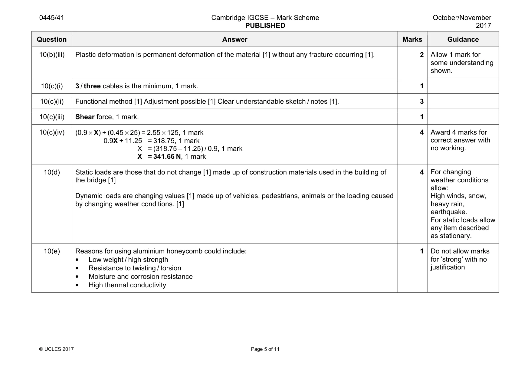
Mark scheme: 10(a) Part ......A........ is a strut, which is placed there to resist compression Part ......B........ is a tie which will resist tension When the roof covering is added part C will have to resist a bending force. 5 1 mark for each term correctly placed 10(b)(i) Elastic deformation allows the material to go back to its original shape / length [1] after the loading is removed [1] 2 Allow 1 mark for some understanding shown. 10(b)(ii) Elastic limit is the maximum that a material can be stretched [1] without any permanent change to its shape / length [1]. 2 Allow 1 mark for some understanding shown. Question Answer Marks Guidance 10(b)(iii) Plastic deformation is permanent deformation of the material [1] without any fracture occurring [1]. 2 Allow 1 mark for some understanding shown. 10(c)(i) 3 / three cables is the minimum, 1 mark. 1 10(c)(ii) Functional method [1] Adjustment possible [1] Clear understandable sketch / notes [1]. 3 10(c)(iii) Shear force, 1 mark. 1 10(c)(iv) (0.9 × X) + (0.45 × 25) = 2.55 × 125, 1 mark 0.9X + 11.25 = 318.75, 1 mark X = (318.75 – 11.25) / 0.9, 1 mark X = 341.66 N, 1 mark 4 Award 4 marks for correct answer with no working. 10(d) Static loads are those that do not change [1] made up of construction materials used in the building of the bridge [1] Dynamic loads are changing values [1] made up of vehicles, pedestrians, animals or the loading caused by changing weather conditions. [1] 4 For changing weather conditions allow: High winds, snow, heavy rain, earthquake. For static loads allow any item described as stationary. 10(e) Reasons for using aluminium honeycomb could include: • Low weight / high strength • Resistance to twisting / torsion • Moisture and corrosion resistance • High thermal conductivity 1 Do not allow marks for ‘strong’ with no justification
Q11 · Power sources used to operate mechanisms usually have safety features that will prevent…
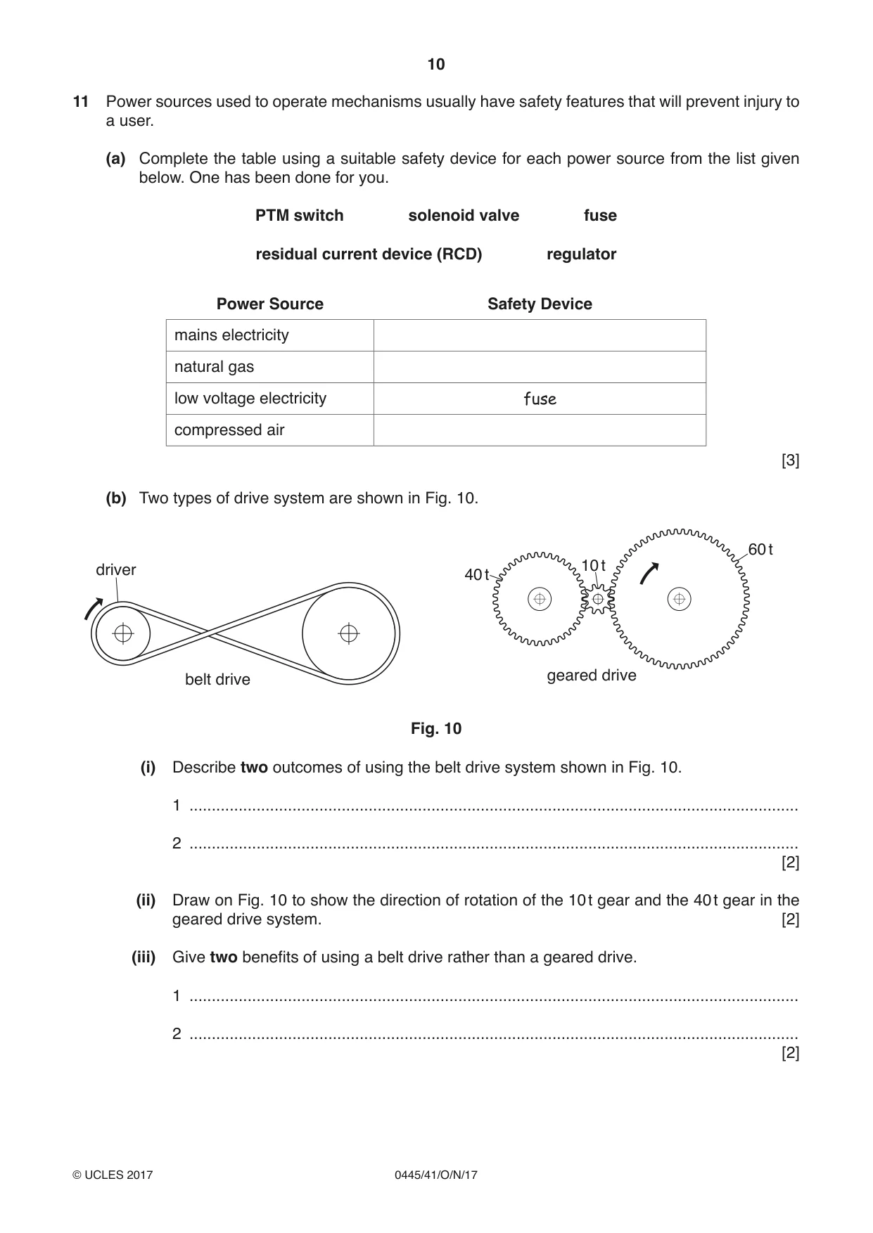
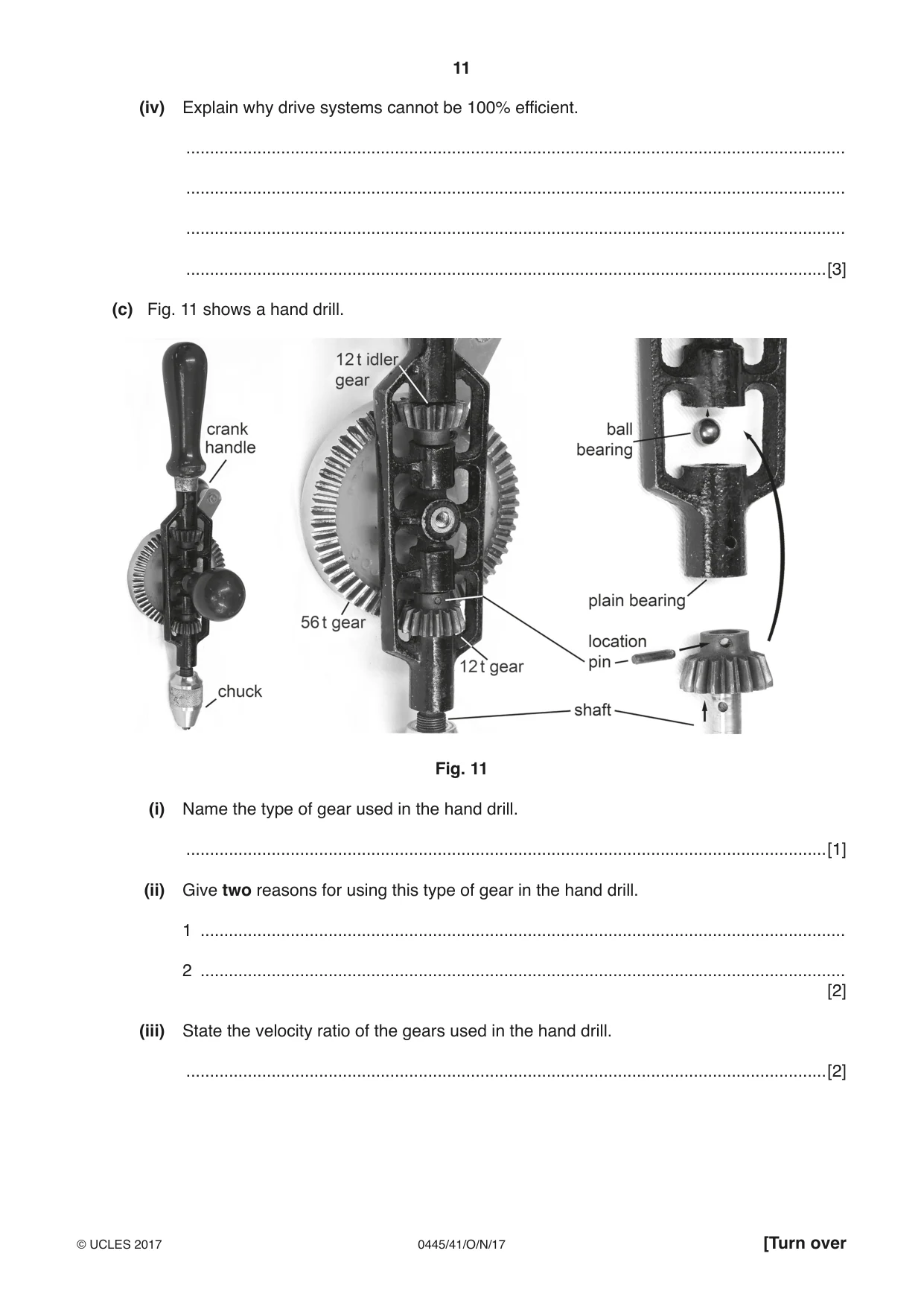
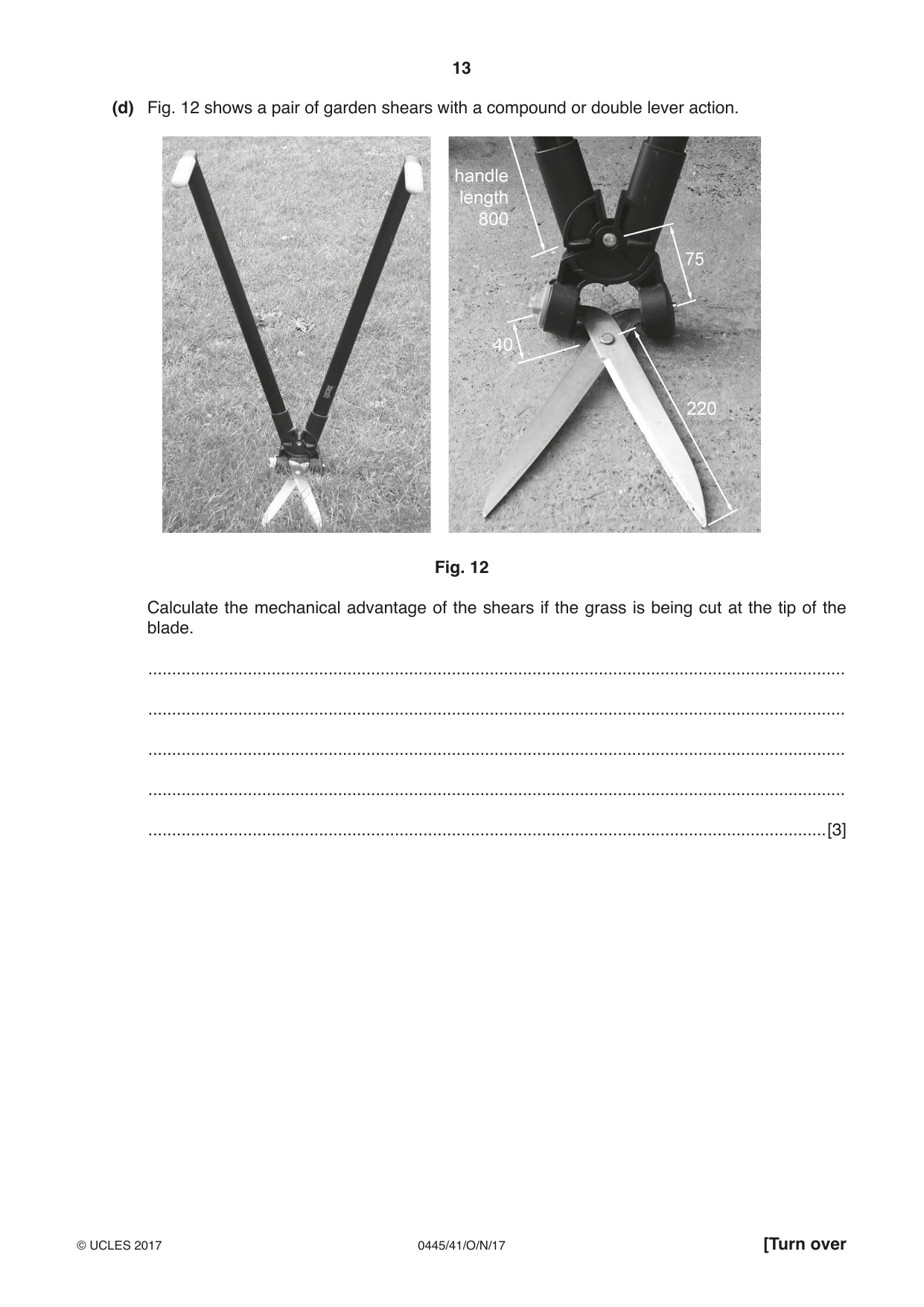
11 Power sources used to operate mechanisms usually have safety features that will prevent injury to a user. (a) Complete the table using a suitable safety device for each power source from the list given below. One has been done for you. PTM switch solenoid valve fuse residual current device (RCD) regulator Power Source Safety Device mains electricity natural gas low voltage electricity fuse compressed air [3] (b) Two types of drive system are shown in Fig. 10. 60 t driver 10 t 40 t belt drive geared drive Fig. 10 (i) Describe two outcomes of using the belt drive system shown in Fig. 10. 1 ........................................................................................................................................ 2 ........................................................................................................................................ [2] (ii) Draw on Fig. 10 to show the direction of rotation of the 10 t gear and the 40 t gear in the geared drive system. [2] (iii) Give two benefits of using a belt drive rather than a geared drive. 1 ........................................................................................................................................ 2 ........................................................................................................................................ [2] (iv) Explain why drive systems cannot be 100% efficient. ........................................................................................................................................... ........................................................................................................................................... ........................................................................................................................................... .......................................................................................................................................[3] (c) Fig. 11 shows a hand drill. Fig. 11 (i) Name the type of gear used in the hand drill. .......................................................................................................................................[1] (ii) Give two reasons for using this type of gear in the hand drill. 1 ........................................................................................................................................ 2 ........................................................................................................................................ [2] (iii) State the velocity ratio of the gears used in the hand drill. .......................................................................................................................................[2] (iv) Calculate the speed of the chuck when the handle turns the 56 t gear at 60 rpm. ........................................................................................................................................... ........................................................................................................................................... .......................................................................................................................................[2] (v) The shaft of the hand drill rotates in plain bearings. Give one drawback of using plain bearings. .......................................................................................................................................[1] (vi) The end of the shaft rotates against a ball bearing. Explain why the ball bearing is needed in this position. ........................................................................................................................................... ........................................................................................................................................... ........................................................................................................................................... .......................................................................................................................................[2] (d) Fig. 12 shows a pair of garden shears with a compound or double lever action. Fig. 12 Calculate the mechanical advantage of the shears if the grass is being cut at the tip of the blade. ................................................................................................................................................... ................................................................................................................................................... ................................................................................................................................................... ................................................................................................................................................... ...............................................................................................................................................[3]
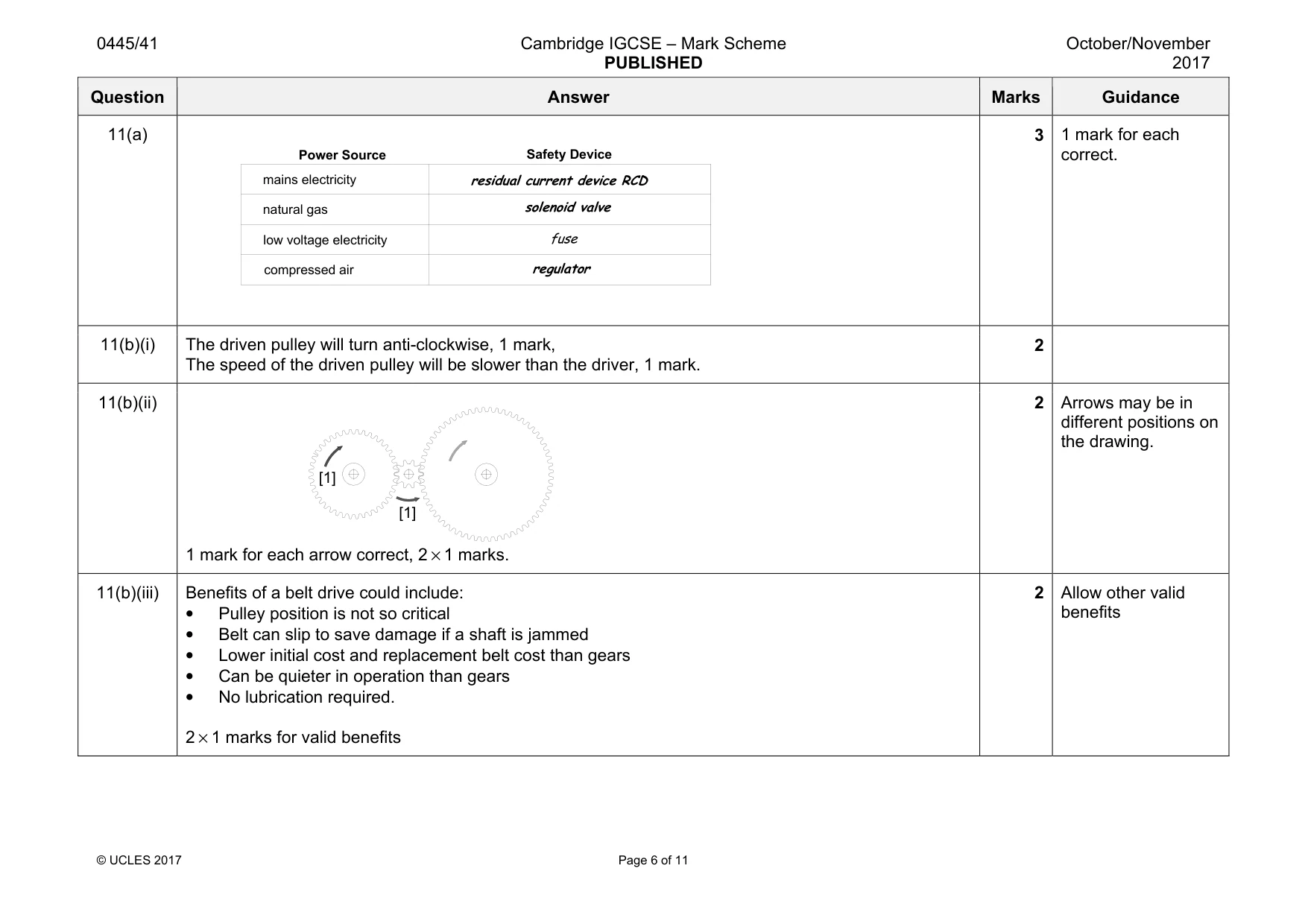
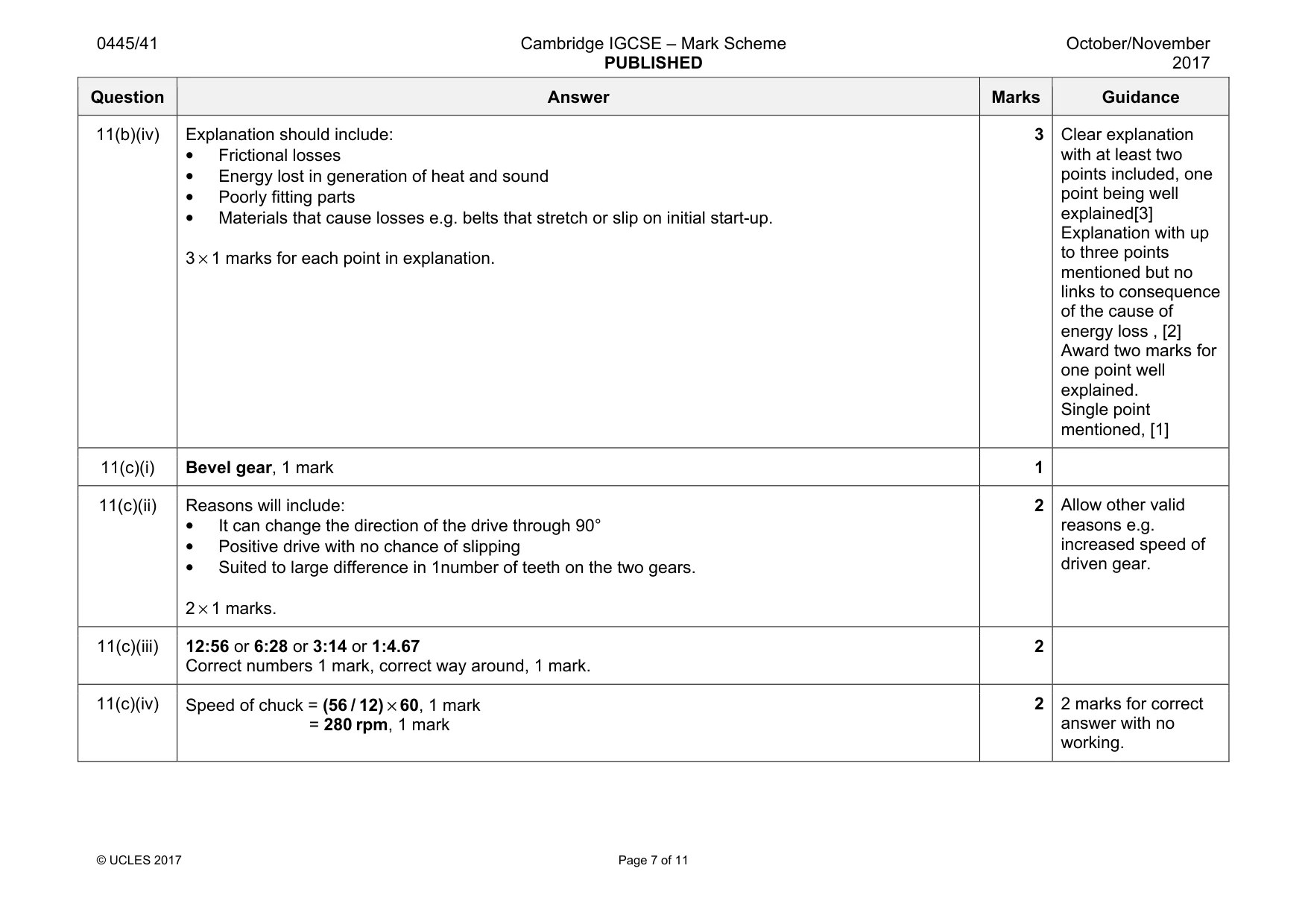
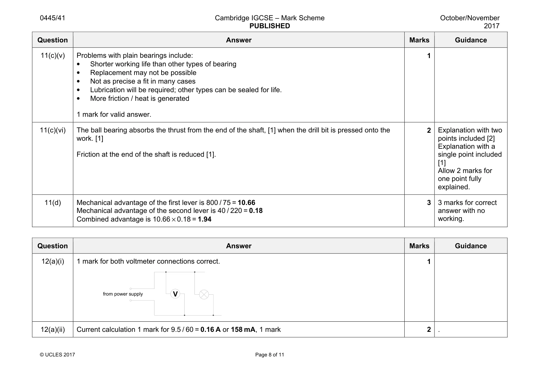
Mark scheme: 11(a) 3 1 mark for each correct. 11(b)(i) The driven pulley will turn anti-clockwise, 1 mark, The speed of the driven pulley will be slower than the driver, 1 mark. 2 11(b)(ii) 1 mark for each arrow correct, 2 × 1 marks. 2 Arrows may be in different positions on the drawing. 11(b)(iii) Benefits of a belt drive could include: • Pulley position is not so critical • Belt can slip to save damage if a shaft is jammed • Lower initial cost and replacement belt cost than gears • Can be quieter in operation than gears • No lubrication required. 2 × 1 marks for valid benefits 2 Allow other valid benefits [1] [1] Power Source Safety Device natural gas compressed air mains electricity low voltage electricity solenoid valve fuse residual current device RCD regulator Question Answer Marks Guidance 11(b)(iv) Explanation should include: • Frictional losses • Energy lost in generation of heat and sound • Poorly fitting parts • Materials that cause losses e.g. belts that stretch or slip on initial start-up. 3 × 1 marks for each point in explanation. 3 Clear explanation with at least two points included, one point being well explained[3] Explanation with up to three points mentioned but no links to consequence of the cause of energy loss , [2] Award two marks for one point well explained. Single point mentioned, [1] 11(c)(i) Bevel gear, 1 mark 1 11(c)(ii) Reasons will include: • It can change the direction of the drive through 90° • Positive drive with no chance of slipping • Suited to large difference in 1number of teeth on the two gears. 2 × 1 marks. 2 Allow other valid reasons e.g. increased speed of driven gear. 11(c)(iii) 12:56 or 6:28 or 3:14 or 1:4.67 Correct numbers 1 mark, correct way around, 1 mark. 2 11(c)(iv) Speed of chuck = (56 / 12) × 60, 1 mark = 280 rpm, 1 mark 2 2 marks for correct answer with no working. Question Answer Marks Guidance 11(c)(v) Problems with plain bearings include: • Shorter working life than other types of bearing • Replacement may not be possible • Not as precise a fit in many cases • Lubrication will be required; other types can be sealed for life. • More friction / heat is generated 1 mark for valid answer. 1 11(c)(vi) The ball bearing absorbs the thrust from the end of the shaft, [1] when the drill bit is pressed onto the work. [1] Friction at the end of the shaft is reduced [1]. 2 Explanation with two points included [2] Explanation with a single point included [1] Allow 2 marks for one point fully explained. 11(d) Mechanical advantage of the first lever is 800 / 75 = 10.66 Mechanical advantage of the second lever is 40 / 220 = 0.18 Combined advantage is 10.66 × 0.18 = 1.94 3 3 marks for correct answer with no working.
Q12 · A voltmeter ready to be connected to a partly completed circuit
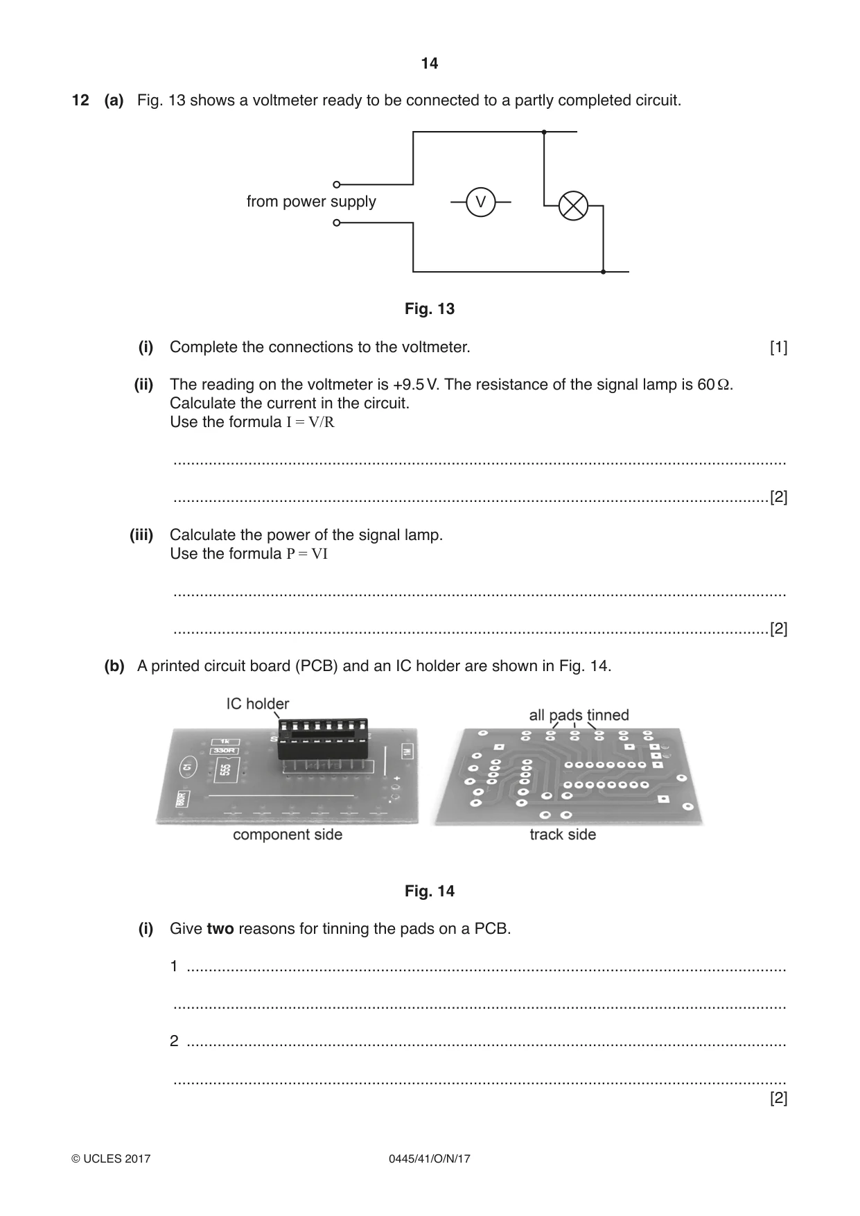
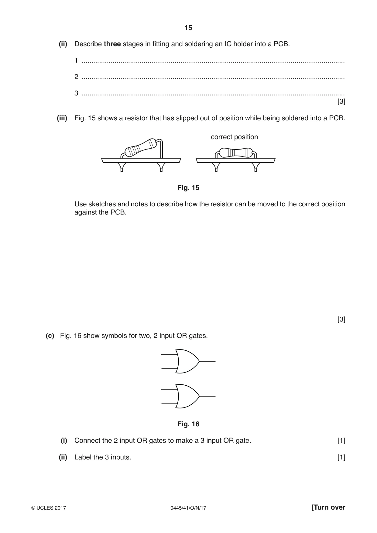
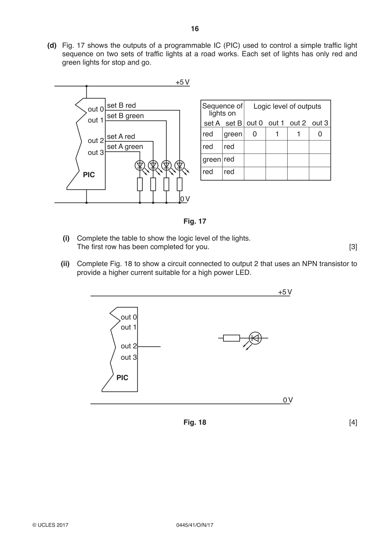
12 (a) Fig. 13 shows a voltmeter ready to be connected to a partly completed circuit. from power supply V Fig. 13 (i) Complete the connections to the voltmeter. [1] (ii) The reading on the voltmeter is +9.5 V. The resistance of the signal lamp is 60 Ω. Calculate the current in the circuit. Use the formula I = V/R ........................................................................................................................................... .......................................................................................................................................[2] (iii) Calculate the power of the signal lamp. Use the formula P = VI ........................................................................................................................................... .......................................................................................................................................[2] (b) A printed circuit board (PCB) and an IC holder are shown in Fig. 14. Fig. 14 (i) Give two reasons for tinning the pads on a PCB. 1 ........................................................................................................................................ ........................................................................................................................................... 2 ........................................................................................................................................ ........................................................................................................................................... [2] (ii) Describe three stages in fitting and soldering an IC holder into a PCB. 1 ........................................................................................................................................ 2 ........................................................................................................................................ 3 ........................................................................................................................................ [3] (iii) Fig. 15 shows a resistor that has slipped out of position while being soldered into a PCB. correct position Fig. 15 Use sketches and notes to describe how the resistor can be moved to the correct position against the PCB. [3] (c) Fig. 16 show symbols for two, 2 input OR gates. Fig. 16 (i) Connect the 2 input OR gates to make a 3 input OR gate. [1] (ii) Label the 3 inputs. [1] (d) Fig. 17 shows the outputs of a programmable IC (PIC) used to control a simple traffic light sequence on two sets of traffic lights at a road works. Each set of lights has only red and green lights for stop and go. +5 V set B red Sequence of Logic level of outputs out 0 lights on set B green out 1 set A set B out 0 out 1 out 2 out 3 red green 0 1 1 0 set A red out 2 set A green red red out 3 green red red red PIC 0 V Fig. 17 (i) Complete the table to show the logic level of the lights. The first row has been completed for you. [3] (ii) Complete Fig. 18 to show a circuit connected to output 2 that uses an NPN transistor to provide a higher current suitable for a high power LED. +5 V out 0 out 1 out 2 out 3 PIC 0 V Fig. 18 [4]
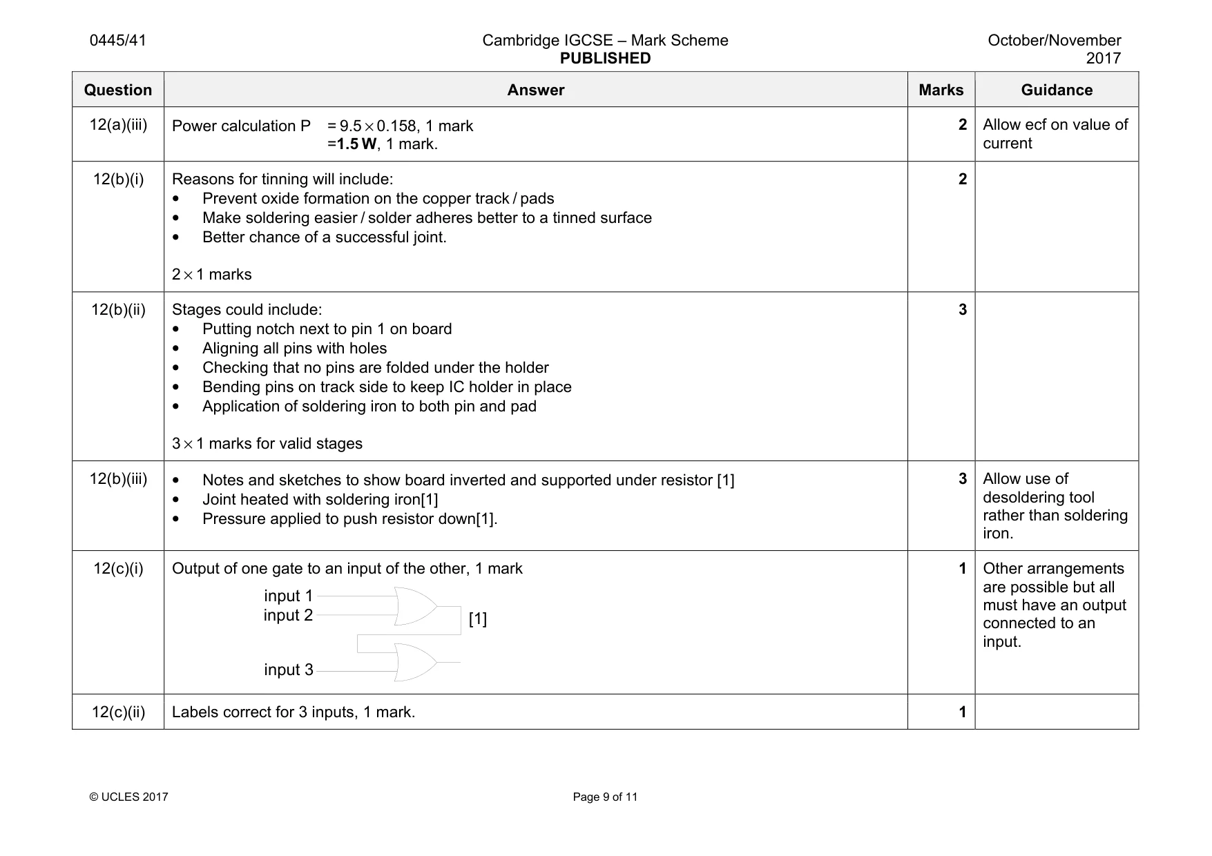
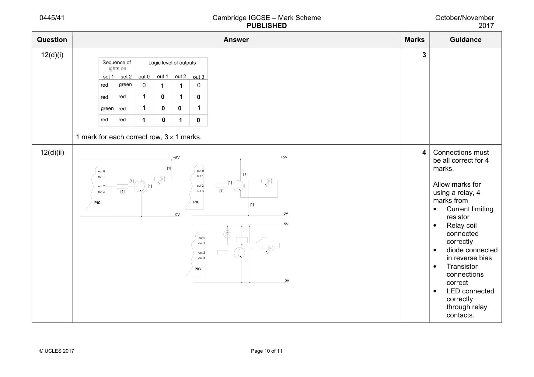
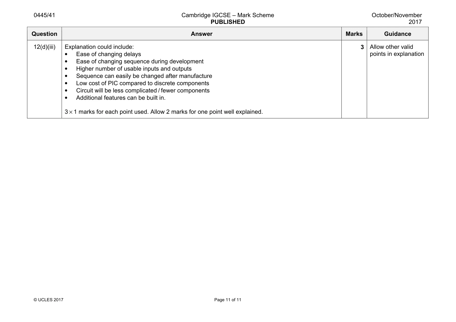
Mark scheme: 12(a)(i) 1 mark for both voltmeter connections correct. 1 12(a)(ii) Current calculation 1 mark for 9.5 / 60 = 0.16 A or 158 mA, 1 mark 2 . V from power supply Question Answer Marks Guidance 12(a)(iii) Power calculation P = 9.5 × 0.158, 1 mark =1.5 W, 1 mark. 2 Allow ecf on value of current 12(b)(i) Reasons for tinning will include: • Prevent oxide formation on the copper track / pads • Make soldering easier / solder adheres better to a tinned surface • Better chance of a successful joint. 2 × 1 marks 2 12(b)(ii) Stages could include: • Putting notch next to pin 1 on board • Aligning all pins with holes • Checking that no pins are folded under the holder • Bending pins on track side to keep IC holder in place • Application of soldering iron to both pin and pad 3 × 1 marks for valid stages 3 12(b)(iii) • Notes and sketches to show board inverted and supported under resistor [1] • Joint heated with soldering iron[1] • Pressure applied to push resistor down[1]. 3 Allow use of desoldering tool rather than soldering iron. 12(c)(i) Output of one gate to an input of the other, 1 mark 1 Other arrangements are possible but all must have an output connected to an input. 12(c)(ii) Labels correct for 3 inputs, 1 mark. 1 [1] input 1 input 2 input 3 Question Answer Marks Guidance 12(d)(i) 1 mark for each correct row, 3 × 1 marks. 3 12(d)(ii) 4 Connections must be all correct for 4 marks. Allow marks for using a relay, 4 marks from • Current limiting resistor • Relay coil connected correctly • diode connected in reverse bias • Transistor connections correct • LED connected correctly through relay contacts. set 1 set 2 red green green red red red red red 0 out 0 out 1 out 2 out 3 1 1 0 Sequence of lights on Logic level of outputs 1 1 1 1 1 1 0 0 0 0 0 0 out 0 out 1 out 2 out 3 PIC +5V 0V [1] [1] [1] [1] out 0 out 1 out 2 out 3 PIC +5V 0V out 0 out 1 out 2 out 3 PIC +5V 0V [1] [1] [1] [1] Question Answer Marks Guidance 12(d)(iii) Explanation could include: • Ease of changing delays • Ease of changing sequence during development • Higher number of usable inputs and outputs • Sequence can easily be changed after manufacture • Low cost of PIC compared to discrete components • Circuit will be less complicated / fewer components • Additional features can be built in. 3 × 1 marks for each point used. Allow 2 marks for one point well explained. 3 Allow other valid points in explanation
What was in this paper
The subtopics covered by these 12 questions, and how many questions each got. Open one in a new tab to see every Cambridge question on it.
What you needed in this session
Cambridge’s own grade thresholds for 2017 Oct/Nov, Paper 4 · Variant 1. A higher threshold means an easier paper — the bar moves with how the cohort did.