Cambridge IGCSE Design and Technology 0445 — 2017 May/June Paper 4 · Variant 3
0445/43/M/J/17 · 10 questions · 50 marks · ≈56 min
The question paper and its mark scheme, free to read here and free to download. This is Cambridge’s own paper, exactly as it was sat.
Question paper20 pages
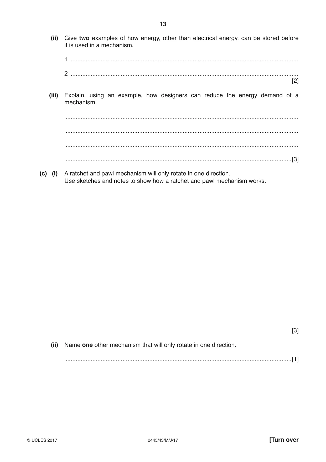
Mark scheme12 pages
Answers below. Sit the paper first if you are practising.
Questions as text
Q1 · Rigid PVC is a plastic often used for the manufacture of door and window frames
1 Rigid PVC is a plastic often used for the manufacture of door and window frames. (a) Give two advantages of using rigid PVC as a structural material when compared to wood. 1 ................................................................................................................................................ ................................................................................................................................................... 2 ................................................................................................................................................ ................................................................................................................................................... [2] (b) Give two advantages of using wood as a structural material when compared to plastics. 1 ................................................................................................................................................ ................................................................................................................................................... 2 ................................................................................................................................................ ................................................................................................................................................... [2]
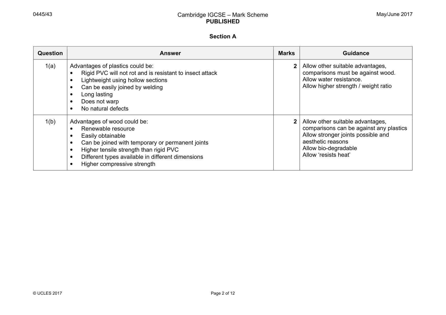
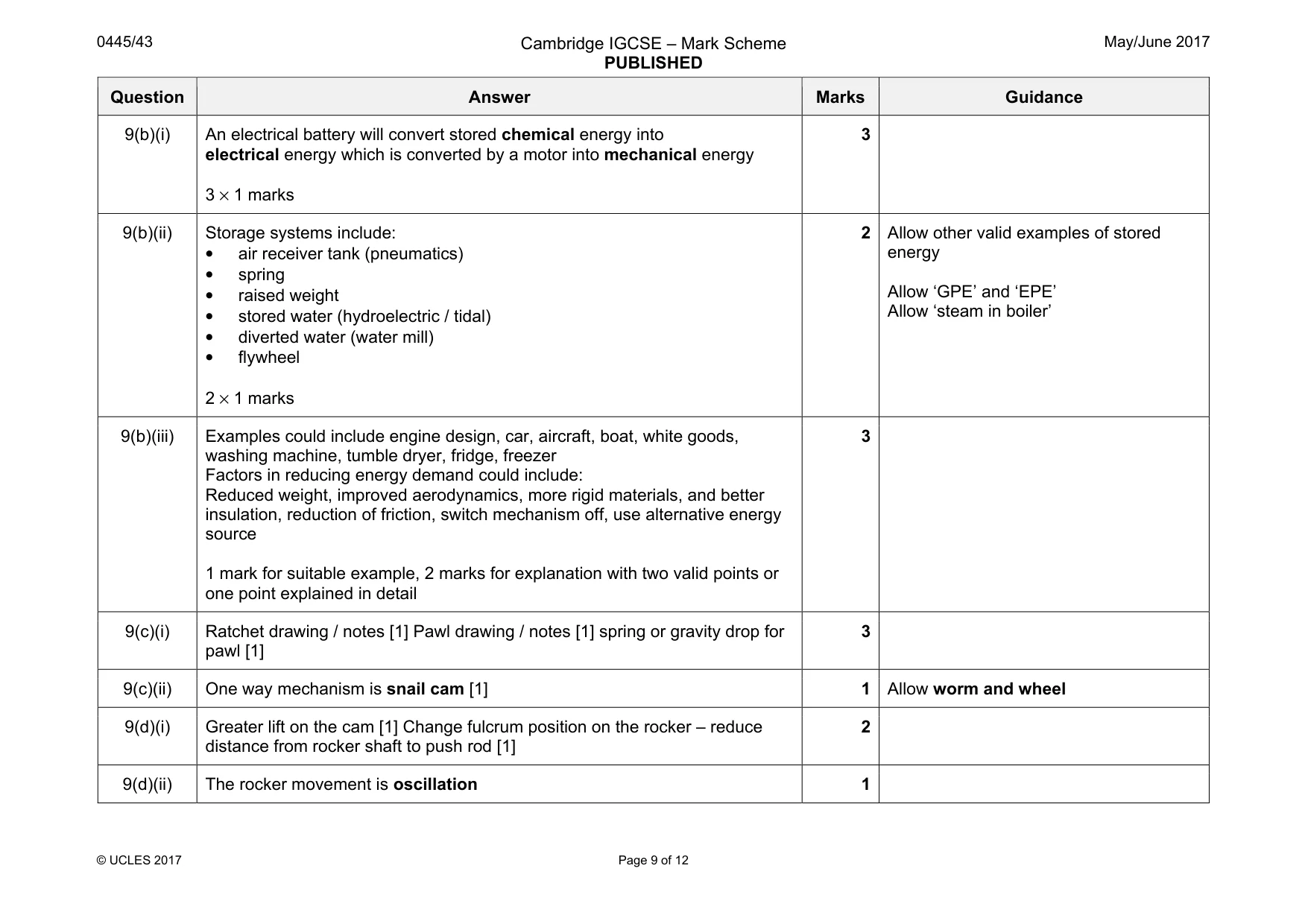
Mark scheme: 1(a) Advantages of plastics could be: • Rigid PVC will not rot and is resistant to insect attack • Lightweight using hollow sections • Can be easily joined by welding • Long lasting • Does not warp • No natural defects 2 Allow other suitable advantages, comparisons must be against wood. Allow water resistance. Allow higher strength / weight ratio 1(b) Advantages of wood could be: • Renewable resource • Easily obtainable • Can be joined with temporary or permanent joints • Higher tensile strength than rigid PVC • Different types available in different dimensions • Higher compressive strength 2 Allow other suitable advantages, comparisons can be against any plastics Allow stronger joints possible and aesthetic reasons Allow bio-degradable Allow ‘resists heat’
Q2 · Two different types of structural beam used to span an opening in a building
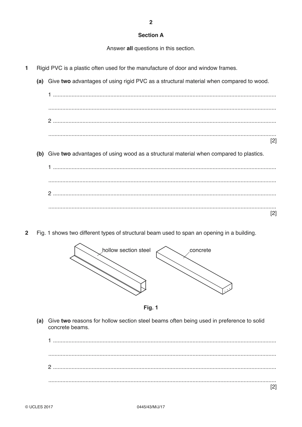
2 Fig. 1 shows two different types of structural beam used to span an opening in a building. hollow section steel concrete Fig. 1 (a) Give two reasons for hollow section steel beams often being used in preference to solid concrete beams. 1 ................................................................................................................................................ ................................................................................................................................................... 2 ................................................................................................................................................ ................................................................................................................................................... [2] (b) Use sketches and notes to show what is meant by a ‘laminated wooden beam’. [2] (c) Give one reason for choosing a laminated wooden beam rather than concrete or hollow section steel. ................................................................................................................................................... ...............................................................................................................................................[1]
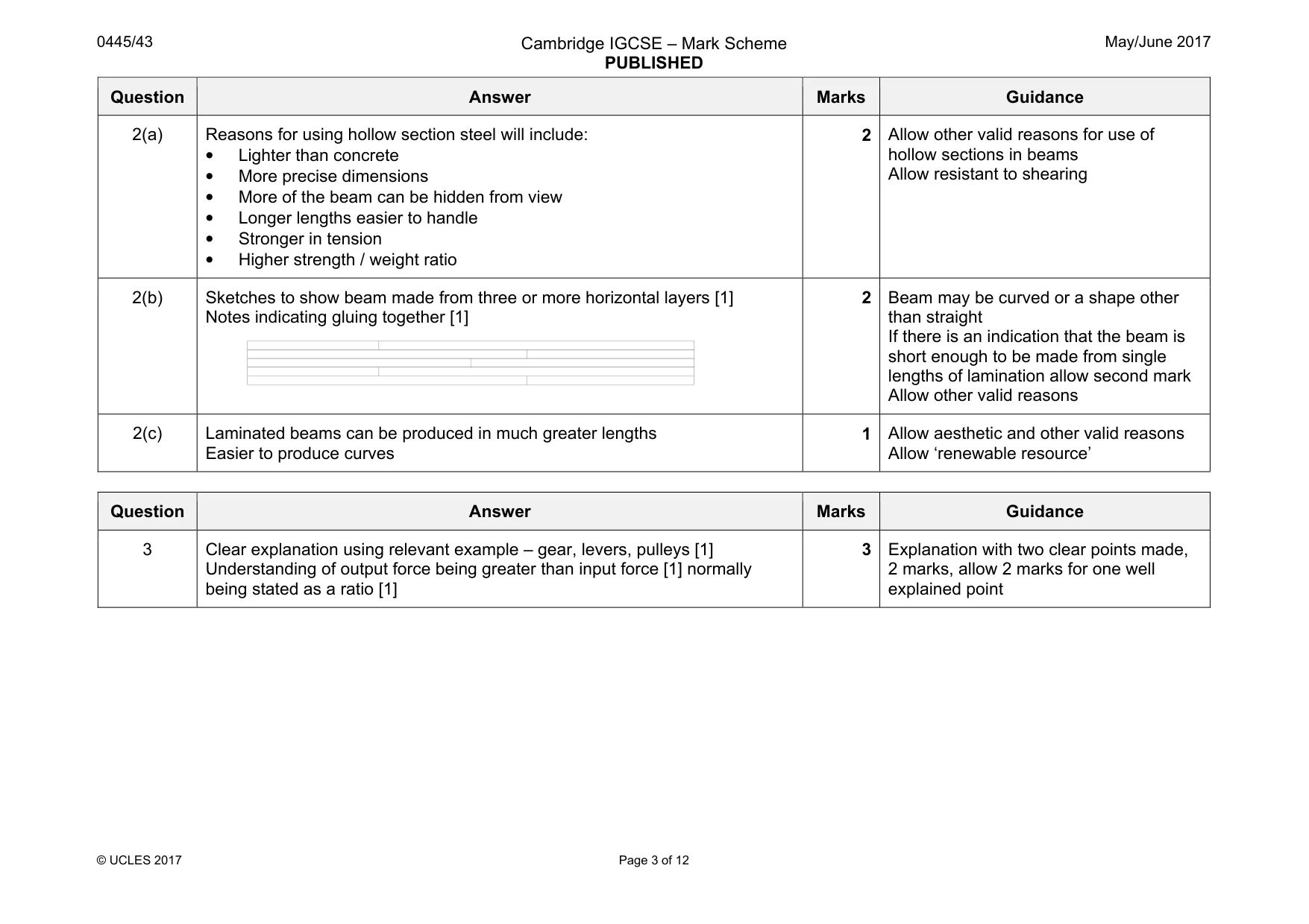
Mark scheme: 2(a) Reasons for using hollow section steel will include: • Lighter than concrete • More precise dimensions • More of the beam can be hidden from view • Longer lengths easier to handle • Stronger in tension • Higher strength / weight ratio 2 Allow other valid reasons for use of hollow sections in beams Allow resistant to shearing 2(b) Sketches to show beam made from three or more horizontal layers [1] Notes indicating gluing together [1] 2 Beam may be curved or a shape other than straight If there is an indication that the beam is short enough to be made from single lengths of lamination allow second mark Allow other valid reasons 2(c) Laminated beams can be produced in much greater lengths Easier to produce curves 1 Allow aesthetic and other valid reasons Allow ‘renewable resource’
Q3 · Explain, using an example, what is meant by ‘mechanical advantage’
3 Explain, using an example, what is meant by ‘mechanical advantage’. .......................................................................................................................................................... .......................................................................................................................................................... .......................................................................................................................................................... ......................................................................................................................................................[3]
Mark scheme: 3 Clear explanation using relevant example – gear, levers, pulleys [1] Understanding of output force being greater than input force [1] normally being stated as a ratio [1] 3 2 marks, allow 2 marks for one well explained point
Q4 · State one reason for using bearings in a machine
4 (a) State one reason for using bearings in a machine. ...............................................................................................................................................[1] (b) Bearings will normally require lubrication. Describe the type of lubrication most suitable for the following purposes. Plain bearings in a car engine .................................................................................................. Ball bearings in a cycle wheel .................................................................................................. [2] (c) Nylon is often used as a material for plain bearings. Give two properties required of nylon when it is used as a bearing material. 1 ................................................................................................................................................ 2 ................................................................................................................................................ [2]
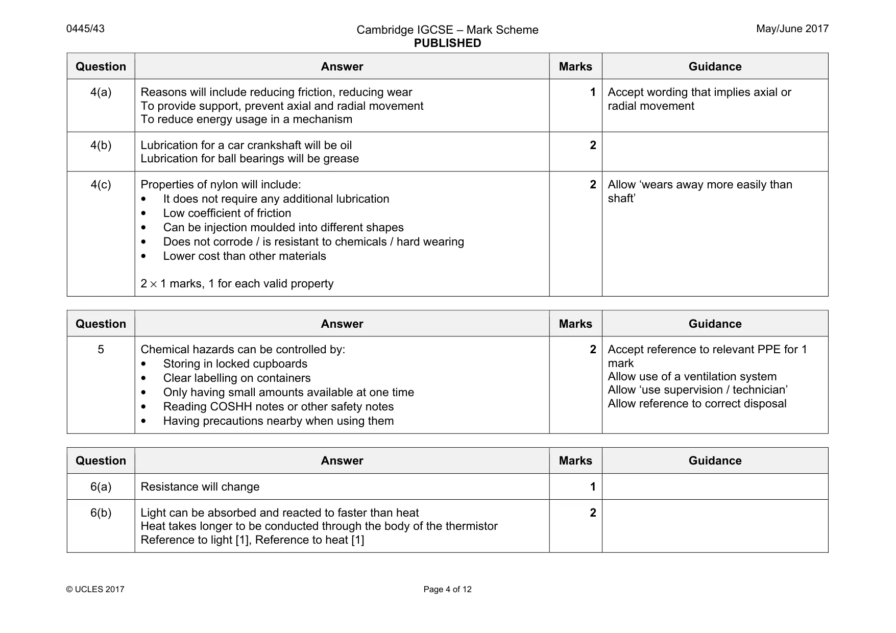
Mark scheme: 4(a) Reasons will include reducing friction, reducing wear To provide support, prevent axial and radial movement To reduce energy usage in a mechanism 1 radial movement 4(b) Lubrication for a car crankshaft will be oil Lubrication for ball bearings will be grease 2 4(c) Properties of nylon will include: • It does not require any additional lubrication • Low coefficient of friction • Can be injection moulded into different shapes • Does not corrode / is resistant to chemicals / hard wearing • Lower cost than other materials 2 × 1 marks, 1 for each valid property 2 Allow ‘wears away more easily than shaft’
Q5 · Printed circuit board (PCB) manufacture can involve the use of hazardous chemicals
5 Printed circuit board (PCB) manufacture can involve the use of hazardous chemicals. Give two ways of controlling these hazards in a school workshop. 1 ....................................................................................................................................................... 2 ....................................................................................................................................................... [2]
Mark scheme: 5 Chemical hazards can be controlled by: • Storing in locked cupboards • Clear labelling on containers • Only having small amounts available at one time • Reading COSHH notes or other safety notes • Having precautions nearby when using them 2 mark Allow use of a ventilation system Allow ‘use supervision / technician’ Allow reference to correct disposal
Q6 · Two input transducers with their circuit symbols
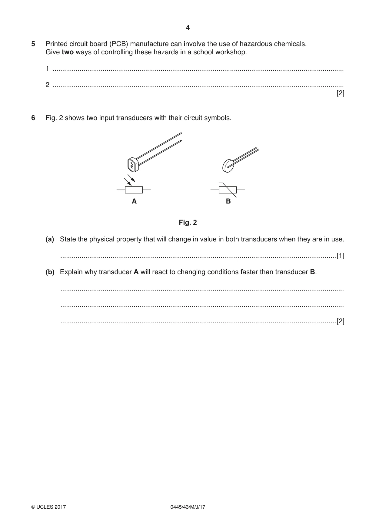
6 Fig. 2 shows two input transducers with their circuit symbols. A B Fig. 2 (a) State the physical property that will change in value in both transducers when they are in use. ...............................................................................................................................................[1] (b) Explain why transducer A will react to changing conditions faster than transducer B. ................................................................................................................................................... ................................................................................................................................................... ...............................................................................................................................................[2]
Mark scheme: 6(a) Resistance will change 1 6(b) Light can be absorbed and reacted to faster than heat Heat takes longer to be conducted through the body of the thermistor Reference to light [1], Reference to heat [1] 2
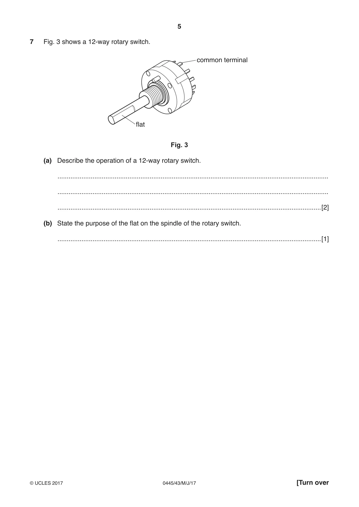
Q7 · A 12-way rotary switch
7 Fig. 3 shows a 12-way rotary switch. common terminal flat Fig. 3 (a) Describe the operation of a 12-way rotary switch. ................................................................................................................................................... ................................................................................................................................................... ...............................................................................................................................................[2] (b) State the purpose of the flat on the spindle of the rotary switch. ...............................................................................................................................................[1]
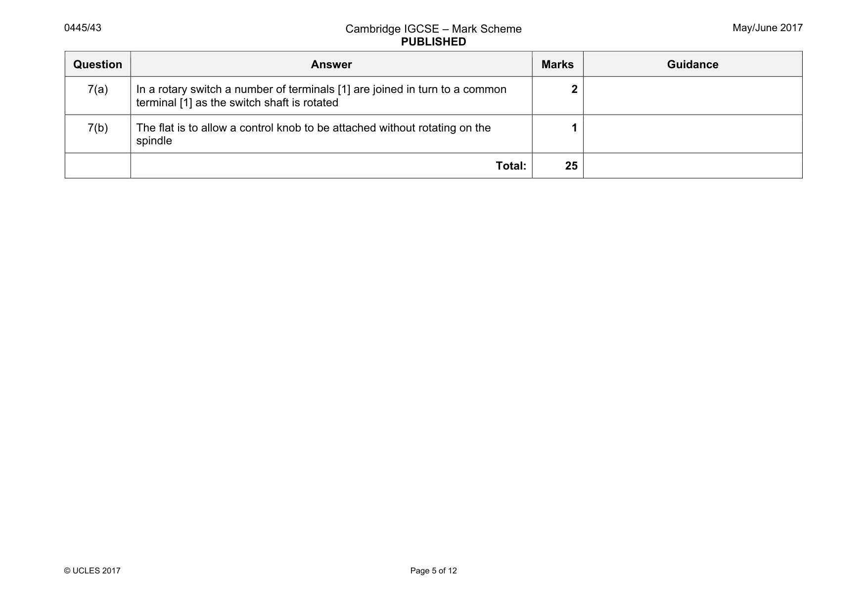
Mark scheme: 7(a) In a rotary switch a number of terminals [1] are joined in turn to a common terminal [1] as the switch shaft is rotated 2 7(b) The flat is to allow a control knob to be attached without rotating on the spindle 1 Total: 25
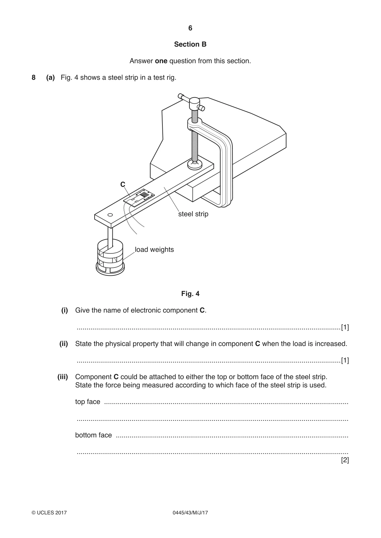
Q8 · A steel strip in a test rig
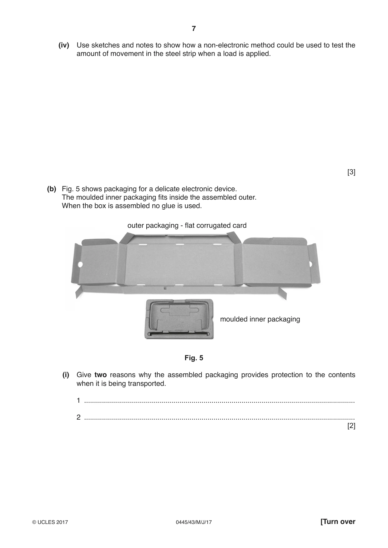
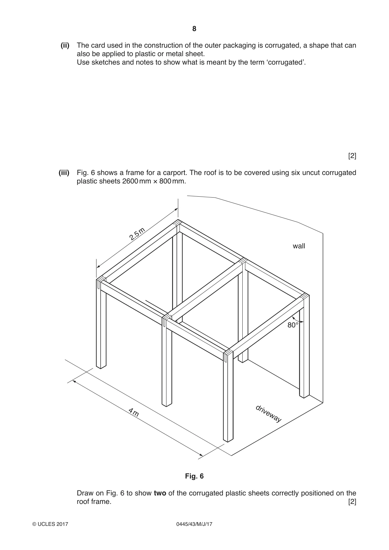
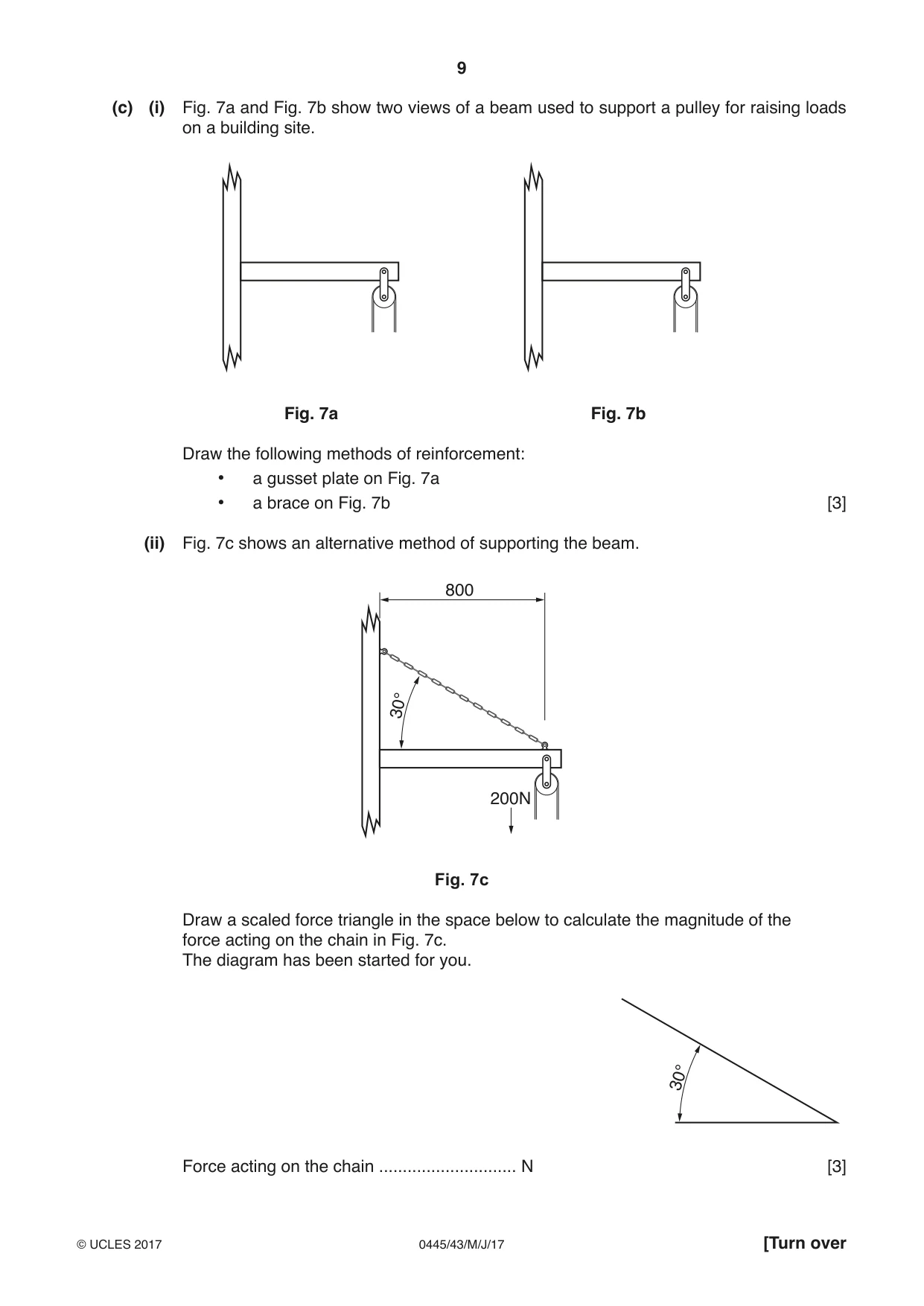
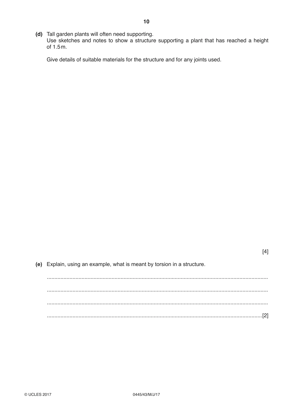
8 (a) Fig. 4 shows a steel strip in a test rig. C steel strip load weights Fig. 4 (i) Give the name of electronic component C. .......................................................................................................................................[1] (ii) State the physical property that will change in component C when the load is increased. .......................................................................................................................................[1] (iii) Component C could be attached to either the top or bottom face of the steel strip. State the force being measured according to which face of the steel strip is used. top face ............................................................................................................................. ........................................................................................................................................... bottom face ....................................................................................................................... ........................................................................................................................................... [2] (iv) Use sketches and notes to show how a non-electronic method could be used to test the amount of movement in the steel strip when a load is applied. [3] (b) Fig. 5 shows packaging for a delicate electronic device. The moulded inner packaging fits inside the assembled outer. When the box is assembled no glue is used. outer packaging - flat corrugated card moulded inner packaging Fig. 5 (i) Give two reasons why the assembled packaging provides protection to the contents when it is being transported. 1 ........................................................................................................................................ 2 ........................................................................................................................................ [2] (ii) The card used in the construction of the outer packaging is corrugated, a shape that can also be applied to plastic or metal sheet. Use sketches and notes to show what is meant by the term ‘corrugated’. [2] (iii) Fig. 6 shows a frame for a carport. The roof is to be covered using six uncut corrugated plastic sheets 2600 mm × 800 mm. m 2.5 wall 80° 4 m driveway Fig. 6 Draw on Fig. 6 to show two of the corrugated plastic sheets correctly positioned on the roof frame. [2] (c) (i) Fig. 7a and Fig. 7b show two views of a beam used to support a pulley for raising loads on a building site. Fig. 7a Fig. 7b Draw the following methods of reinforcement: • a gusset plate on Fig. 7a • a brace on Fig. 7b [3] (ii) Fig. 7c shows an alternative method of supporting the beam. 800 30° 200N Fig. 7c Draw a scaled force triangle in the space below to calculate the magnitude of the force acting on the chain in Fig. 7c. The diagram has been started for you. 30° Force acting on the chain ............................. N [3] (d) Tall garden plants will often need supporting. Use sketches and notes to show a structure supporting a plant that has reached a height of 1.5 m. Give details of suitable materials for the structure and for any joints used. [4] (e) Explain, using an example, what is meant by torsion in a structure. ................................................................................................................................................... ................................................................................................................................................... ................................................................................................................................................... ...............................................................................................................................................[2]
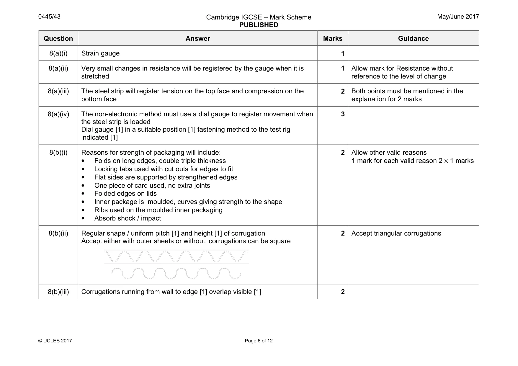
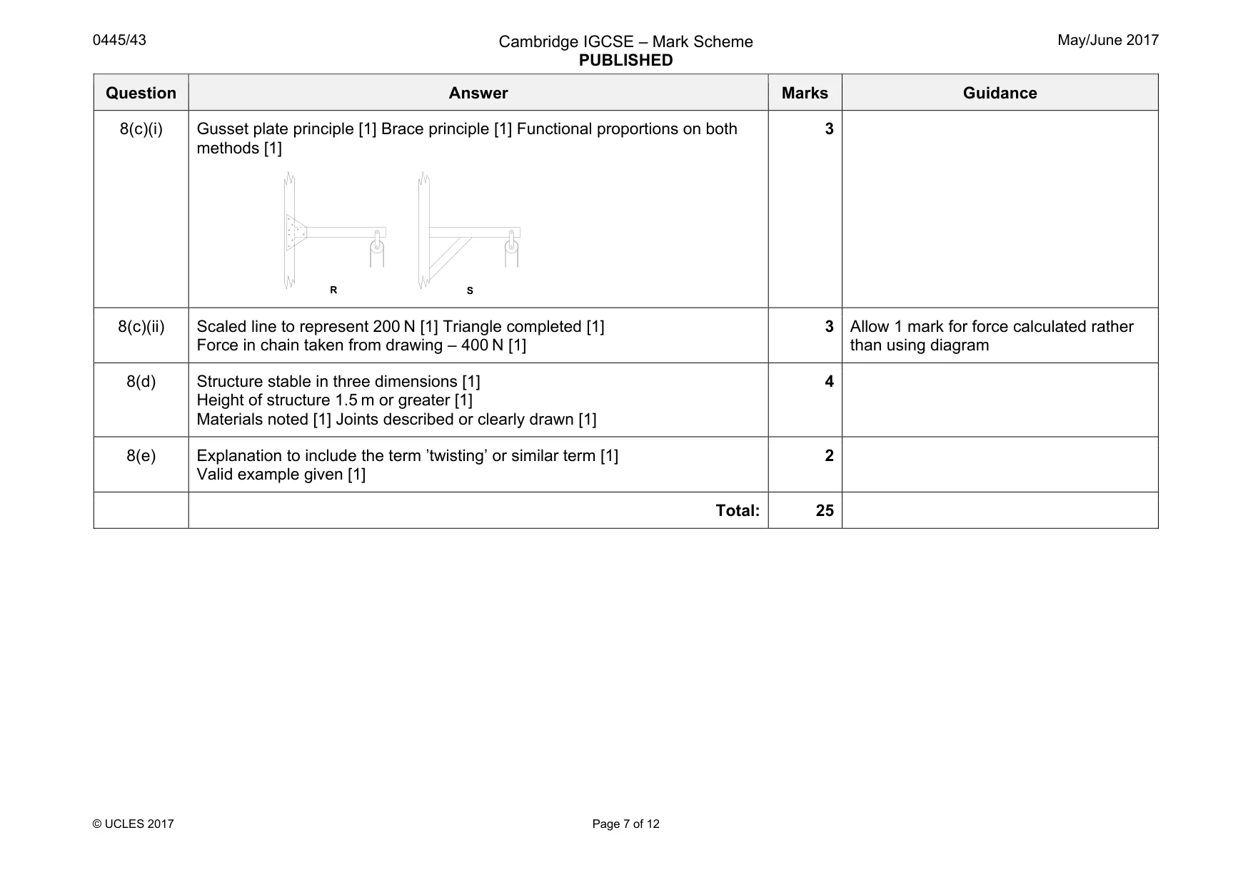
Mark scheme: 8(a)(i) Strain gauge 1 8(a)(ii) Very small changes in resistance will be registered by the gauge when it is stretched 1 Allow mark for Resistance without reference to the level of change 8(a)(iii) The steel strip will register tension on the top face and compression on the bottom face 2 Both points must be mentioned in the explanation for 2 marks 8(a)(iv) The non-electronic method must use a dial gauge to register movement when the steel strip is loaded Dial gauge [1] in a suitable position [1] fastening method to the test rig indicated [1] 3 8(b)(i) Reasons for strength of packaging will include: • Folds on long edges, double triple thickness • Locking tabs used with cut outs for edges to fit • Flat sides are supported by strengthened edges • One piece of card used, no extra joints • Folded edges on lids • Inner package is moulded, curves giving strength to the shape • Ribs used on the moulded inner packaging • Absorb shock / impact 2 Allow other valid reasons 1 mark for each valid reason 2 × 1 marks 8(b)(ii) Regular shape / uniform pitch [1] and height [1] of corrugation Accept either with outer sheets or without, corrugations can be square 2 Accept triangular corrugations 8(b)(iii) Corrugations running from wall to edge [1] overlap visible [1] 2 Question Answer Marks Guidance 8(c)(i) Gusset plate principle [1] Brace principle [1] Functional proportions on both methods [1] 3 8(c)(ii) Scaled line to represent 200 N [1] Triangle completed [1] Force in chain taken from drawing – 400 N [1] 3 Allow 1 mark for force calculated rather than using diagram 8(d) Structure stable in three dimensions [1] Height of structure 1.5 m or greater [1] Materials noted [1] Joints described or clearly drawn [1] 4 8(e) Explanation to include the term ’twisting’ or similar term [1] Valid example given [1] 2 Total: 25 R S
Q9 · A cycle brake lever in the released and pulled position and the brake mechanism
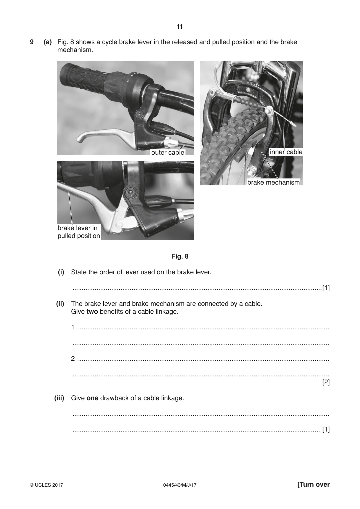
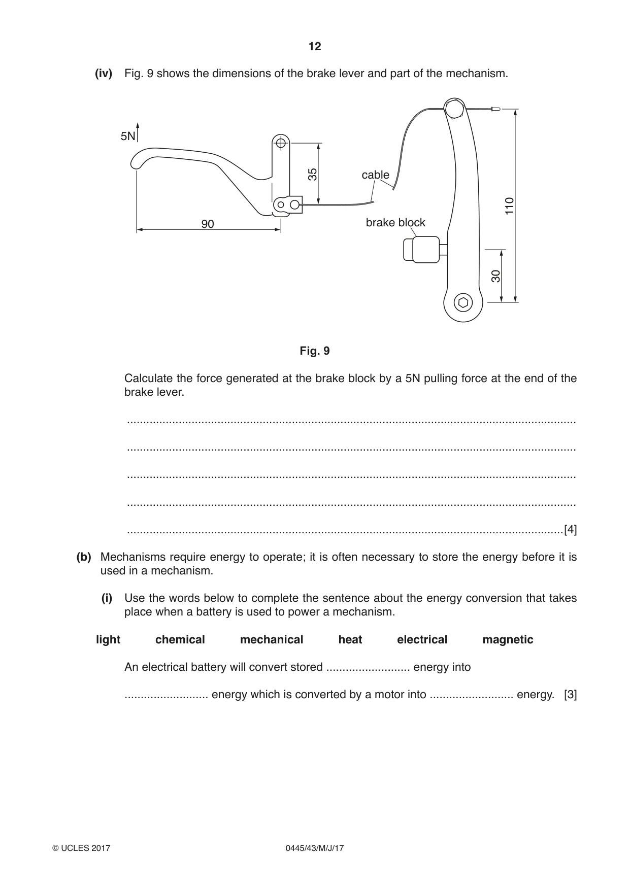
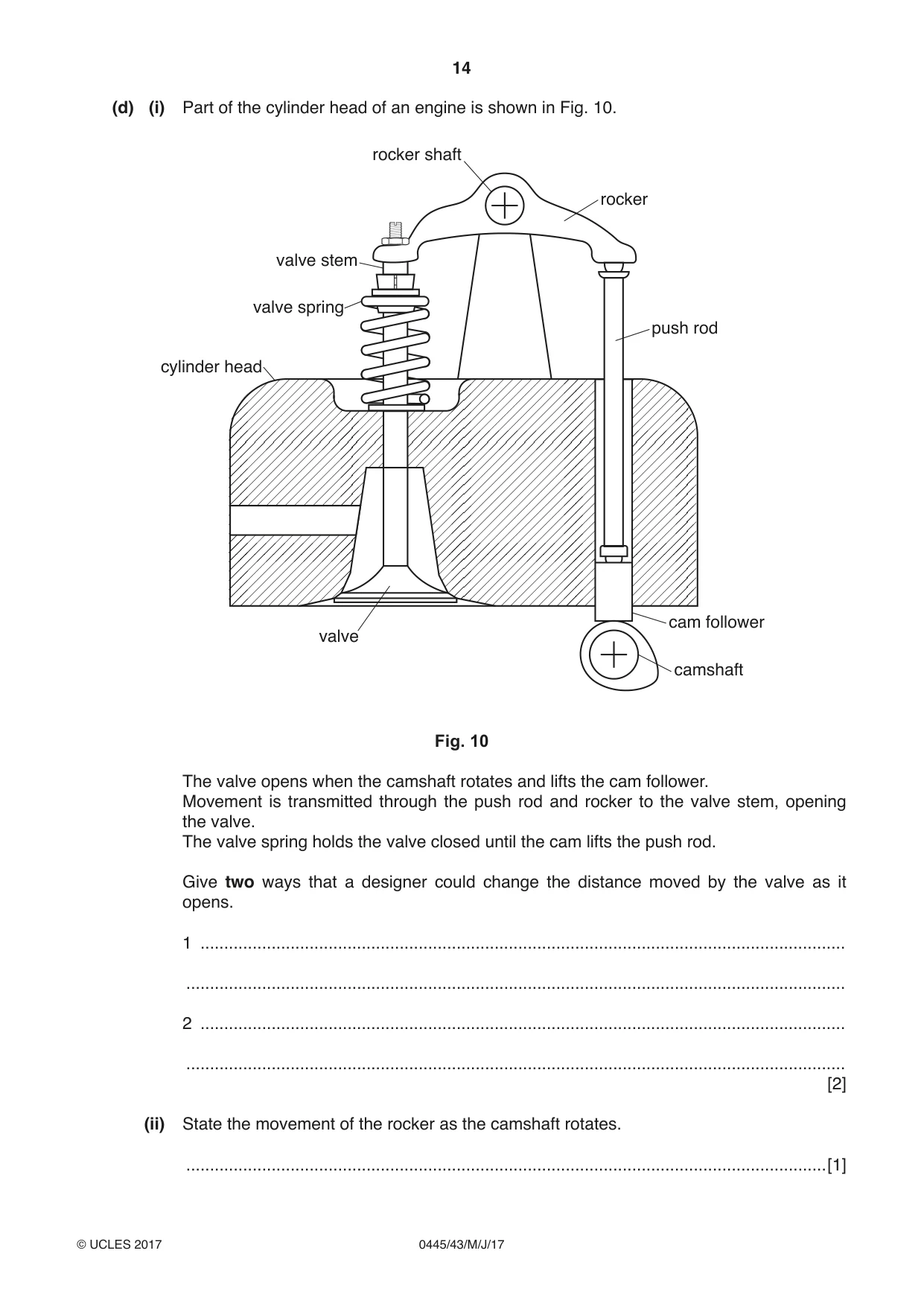
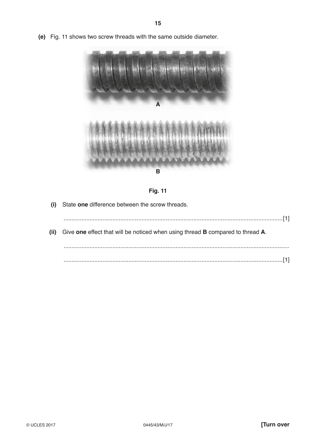
9 (a) Fig. 8 shows a cycle brake lever in the released and pulled position and the brake mechanism. outer cable inner cable brake mechanism brake lever in pulled position Fig. 8 (i) State the order of lever used on the brake lever. .......................................................................................................................................[1] (ii) The brake lever and brake mechanism are connected by a cable. Give two benefits of a cable linkage. 1 ........................................................................................................................................ ........................................................................................................................................... 2 ........................................................................................................................................ ........................................................................................................................................... [2] (iii) Give one drawback of a cable linkage. ........................................................................................................................................... ...................................................................................................................................... [1] (iv) Fig. 9 shows the dimensions of the brake lever and part of the mechanism. 5N 35 cable 110 90 brake block 30 Fig. 9 Calculate the force generated at the brake block by a 5N pulling force at the end of the brake lever. ........................................................................................................................................... ........................................................................................................................................... ........................................................................................................................................... ........................................................................................................................................... .......................................................................................................................................[4] (b) Mechanisms require energy to operate; it is often necessary to store the energy before it is used in a mechanism. (i) Use the words below to complete the sentence about the energy conversion that takes place when a battery is used to power a mechanism. light chemical mechanical heat electrical magnetic An electrical battery will convert stored .......................... energy into .......................... energy which is converted by a motor into .......................... energy. [3] (ii) Give two examples of how energy, other than electrical energy, can be stored before it is used in a mechanism. 1 ........................................................................................................................................ 2 ........................................................................................................................................ [2] (iii) Explain, using an example, how designers can reduce the energy demand of a mechanism. ........................................................................................................................................... ........................................................................................................................................... ........................................................................................................................................... .......................................................................................................................................[3] (c) (i) A ratchet and pawl mechanism will only rotate in one direction. Use sketches and notes to show how a ratchet and pawl mechanism works. [3] (ii) Name one other mechanism that will only rotate in one direction. .......................................................................................................................................[1] (d) (i) Part of the cylinder head of an engine is shown in Fig. 10. rocker shaft rocker valve stem valve spring push rod cylinder head cam follower valve camshaft Fig. 10 The valve opens when the camshaft rotates and lifts the cam follower. Movement is transmitted through the push rod and rocker to the valve stem, opening the valve. The valve spring holds the valve closed until the cam lifts the push rod. Give two ways that a designer could change the distance moved by the valve as it opens. 1 ........................................................................................................................................ ........................................................................................................................................... 2 ........................................................................................................................................ ........................................................................................................................................... [2] (ii) State the movement of the rocker as the camshaft rotates. .......................................................................................................................................[1] (e) Fig. 11 shows two screw threads with the same outside diameter. A B Fig. 11 (i) State one difference between the screw threads. .......................................................................................................................................[1] (ii) Give one effect that will be noticed when using thread B compared to thread A. ........................................................................................................................................... .......................................................................................................................................[1]
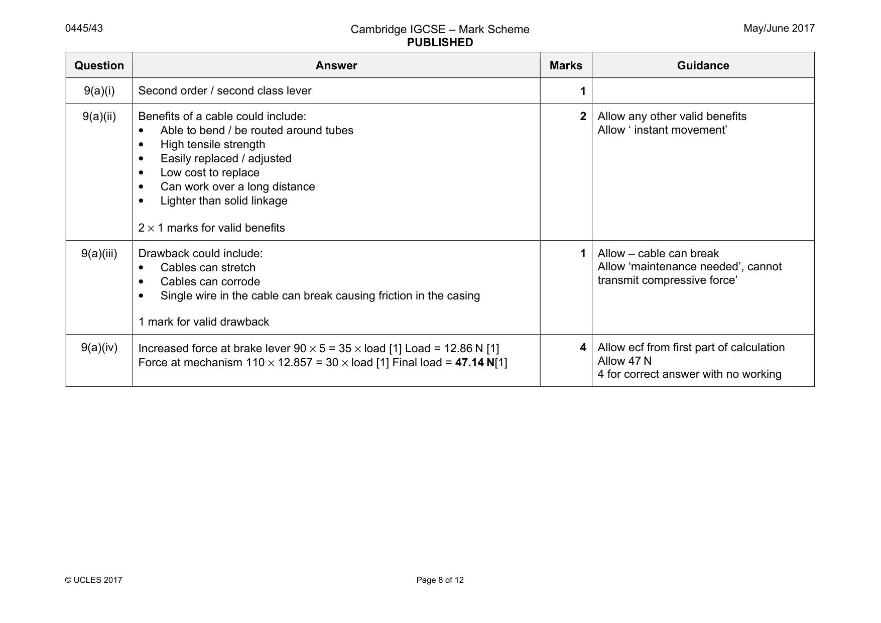
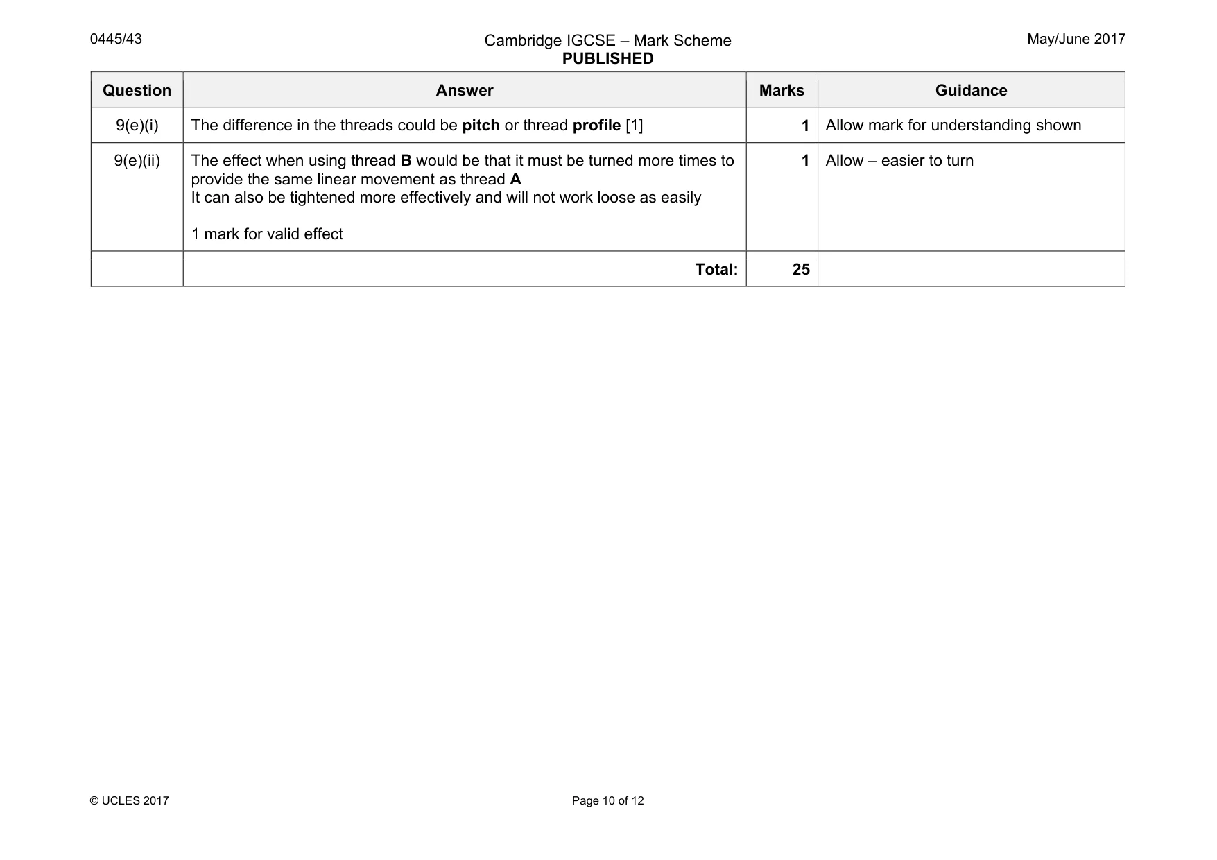
Mark scheme: 9(a)(i) Second order / second class lever 1 9(a)(ii) Benefits of a cable could include: • Able to bend / be routed around tubes • High tensile strength • Easily replaced / adjusted • Low cost to replace • Can work over a long distance • Lighter than solid linkage 2 × 1 marks for valid benefits 2 Allow any other valid benefits Allow ‘ instant movement’ 9(a)(iii) Drawback could include: • Cables can stretch • Cables can corrode • Single wire in the cable can break causing friction in the casing 1 mark for valid drawback 1 Allow – cable can break Allow ‘maintenance needed’, cannot transmit compressive force’ 9(a)(iv) Increased force at brake lever 90 × 5 = 35 × load [1] Load = 12.86 N [1] Force at mechanism 110 × 12.857 = 30 × load [1] Final load = 47.14 N[1] 4 Allow ecf from first part of calculation Allow 47 N 4 for correct answer with no working Question Answer Marks Guidance 9(b)(i) An electrical battery will convert stored chemical energy into electrical energy which is converted by a motor into mechanical energy 3 × 1 marks 3 9(b)(ii) Storage systems include: • air receiver tank (pneumatics) • spring • raised weight • stored water (hydroelectric / tidal) • diverted water (water mill) • flywheel 2 × 1 marks 2 Allow other valid examples of stored energy Allow ‘GPE’ and ‘EPE’ Allow ‘steam in boiler’ 9(b)(iii) Examples could include engine design, car, aircraft, boat, white goods, washing machine, tumble dryer, fridge, freezer Factors in reducing energy demand could include: Reduced weight, improved aerodynamics, more rigid materials, and better insulation, reduction of friction, switch mechanism off, use alternative energy source 1 mark for suitable example, 2 marks for explanation with two valid points or one point explained in detail 3 9(c)(i) Ratchet drawing / notes [1] Pawl drawing / notes [1] spring or gravity drop for pawl [1] 3 9(c)(ii) One way mechanism is snail cam [1] 1 Allow worm and wheel 9(d)(i) Greater lift on the cam [1] Change fulcrum position on the rocker – reduce distance from rocker shaft to push rod [1] 2 9(d)(ii) The rocker movement is oscillation 1 Question Answer Marks Guidance 9(e)(i) The difference in the threads could be pitch or thread profile [1] 1 Allow mark for understanding shown 9(e)(ii) The effect when using thread B would be that it must be turned more times to provide the same linear movement as thread A It can also be tightened more effectively and will not work loose as easily 1 mark for valid effect 1 Allow – easier to turn Total: 25
Q10 · Four different types of switch
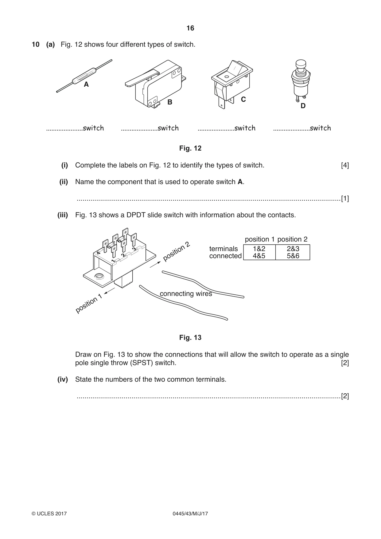
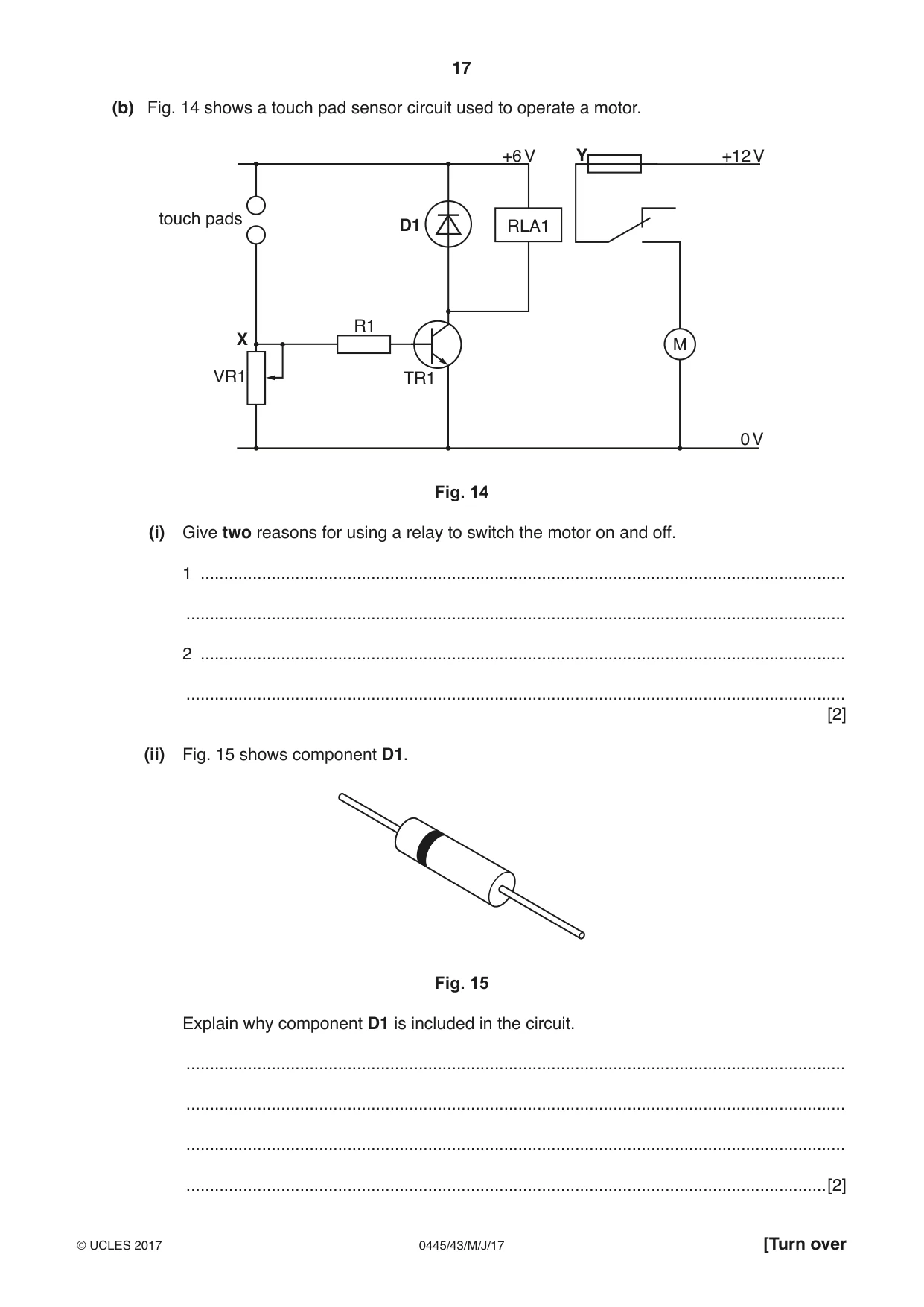
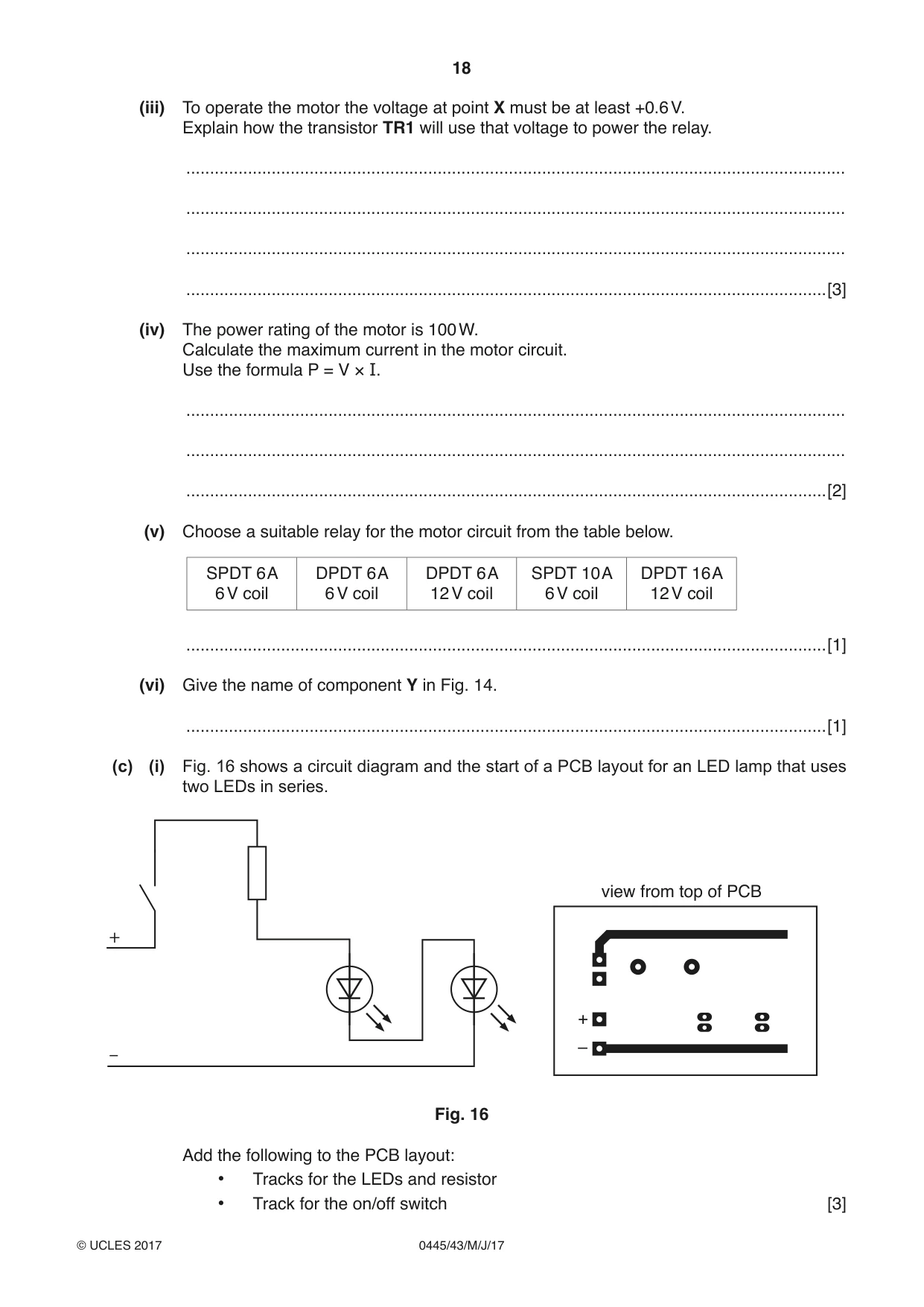
10 (a) Fig. 12 shows four different types of switch. A C B D .....................switch .....................switch .....................switch .....................switch Fig. 12 (i) Complete the labels on Fig. 12 to identify the types of switch. [4] (ii) Name the component that is used to operate switch A. .......................................................................................................................................[1] (iii) Fig. 13 shows a DPDT slide switch with information about the contacts. 6 position 1 position 2 5 2 3 terminals 1&2 2&3 4 2 connected 4&5 5&6 1 position connecting wires 1 position Fig. 13 Draw on Fig. 13 to show the connections that will allow the switch to operate as a single pole single throw (SPST) switch. [2] (iv) State the numbers of the two common terminals. .......................................................................................................................................[2] (b) Fig. 14 shows a touch pad sensor circuit used to operate a motor. +6 V Y +12 V touch pads D1 RLA1 R1 X M VR1 TR1 0 V Fig. 14 (i) Give two reasons for using a relay to switch the motor on and off. 1 ........................................................................................................................................ ........................................................................................................................................... 2 ........................................................................................................................................ ........................................................................................................................................... [2] (ii) Fig. 15 shows component D1. Fig. 15 Explain why component D1 is included in the circuit. ........................................................................................................................................... ........................................................................................................................................... ........................................................................................................................................... .......................................................................................................................................[2] (iii) To operate the motor the voltage at point X must be at least +0.6 V. Explain how the transistor TR1 will use that voltage to power the relay. ........................................................................................................................................... ........................................................................................................................................... ........................................................................................................................................... .......................................................................................................................................[3] (iv) The power rating of the motor is 100 W. Calculate the maximum current in the motor circuit. Use the formula P = V × I. ........................................................................................................................................... ........................................................................................................................................... .......................................................................................................................................[2] (v) Choose a suitable relay for the motor circuit from the table below. SPDT 6 A DPDT 6 A DPDT 6 A SPDT 10 A DPDT 16 A 6 V coil 6 V coil 12 V coil 6 V coil 12 V coil .......................................................................................................................................[1] (vi) Give the name of component Y in Fig. 14. .......................................................................................................................................[1] (c) (i) Fig. 16 shows a circuit diagram and the start of a PCB layout for an LED lamp that uses two LEDs in series. view from top of PCB + + – – Fig. 16 Add the following to the PCB layout: • Tracks for the LEDs and resistor • Track for the on/off switch [3]
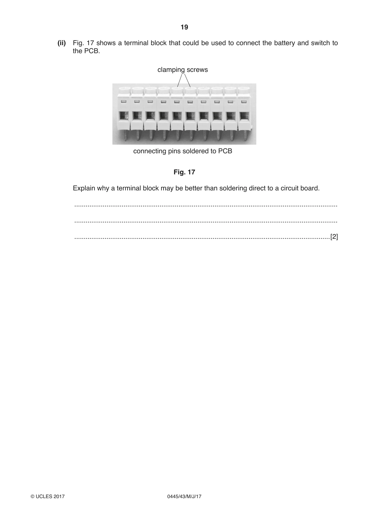
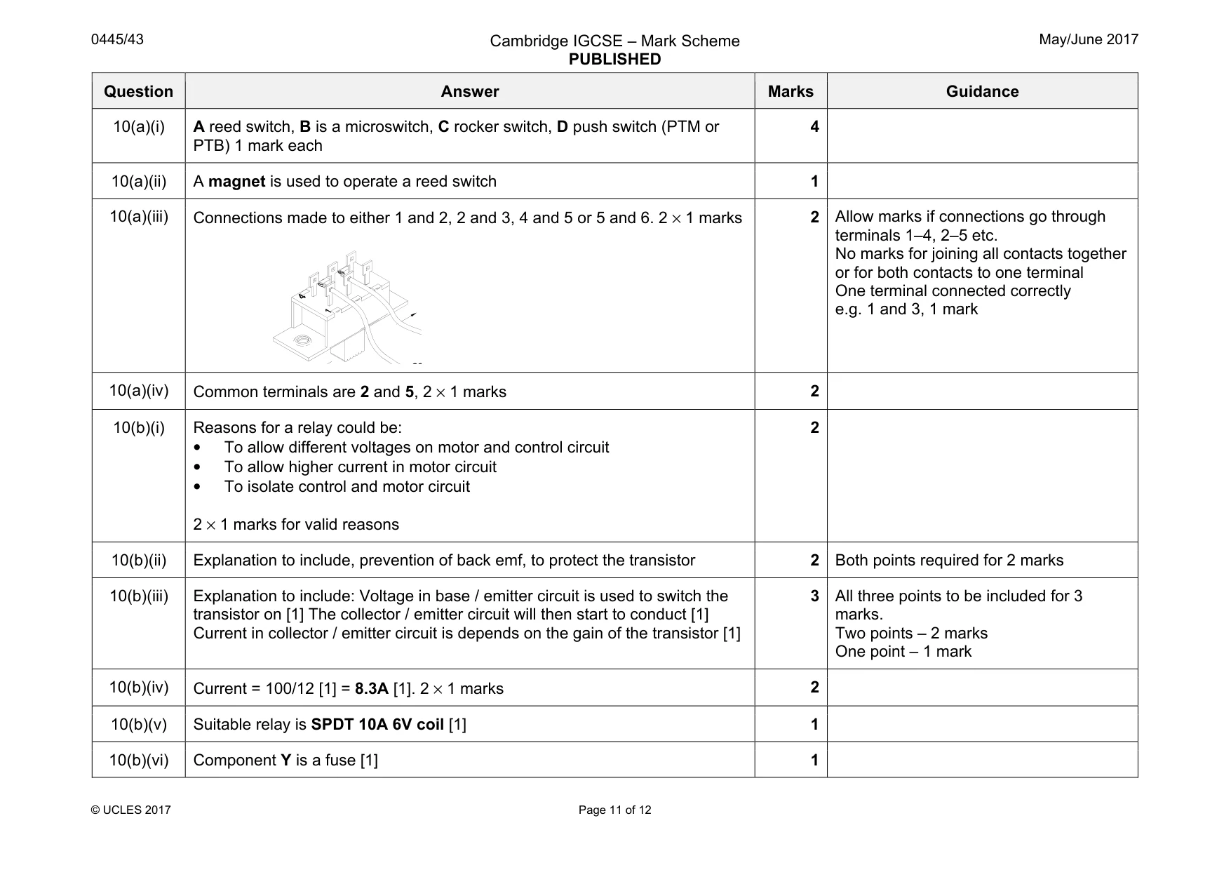
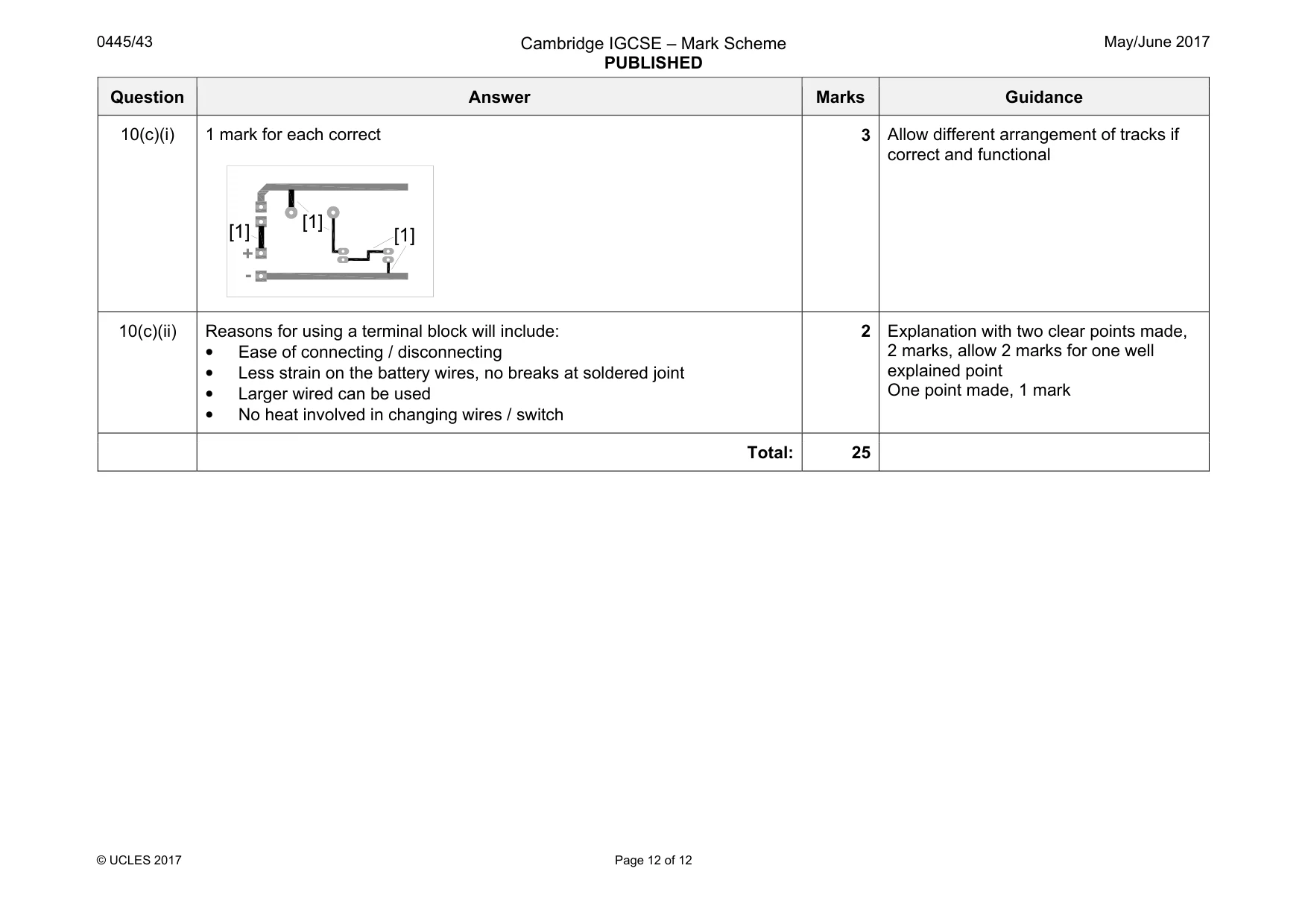
Mark scheme: 10(a)(i) A reed switch, B is a microswitch, C rocker switch, D push switch (PTM or PTB) 1 mark each 4 10(a)(ii) A magnet is used to operate a reed switch 1 10(a)(iii) Connections made to either 1 and 2, 2 and 3, 4 and 5 or 5 and 6. 2 × 1 marks 2 Allow marks if connections go through terminals 1–4, 2–5 etc. No marks for joining all contacts together or for both contacts to one terminal One terminal connected correctly e.g. 1 and 3, 1 mark 10(a)(iv) Common terminals are 2 and 5, 2 × 1 marks 2 10(b)(i) Reasons for a relay could be: • To allow different voltages on motor and control circuit • To allow higher current in motor circuit • To isolate control and motor circuit 2 × 1 marks for valid reasons 2 10(b)(ii) Explanation to include, prevention of back emf, to protect the transistor 2 Both points required for 2 marks 10(b)(iii) Explanation to include: Voltage in base / emitter circuit is used to switch the transistor on [1] The collector / emitter circuit will then start to conduct [1] Current in collector / emitter circuit is depends on the gain of the transistor [1] 3 All three points to be included for 3 marks. Two points – 2 marks One point – 1 mark 10(b)(iv) Current = 100/12 [1] = 8.3A [1]. 2 × 1 marks 2 10(b)(v) Suitable relay is SPDT 10A 6V coil [1] 1 10(b)(vi) Component Y is a fuse [1] 1 co Question Answer Marks Guidance 10(c)(i) 1 mark for each correct 3 Allow different arrangement of tracks if correct and functional 10(c)(ii) Reasons for using a terminal block will include: • Ease of connecting / disconnecting • Less strain on the battery wires, no breaks at soldered joint • Larger wired can be used • No heat involved in changing wires / switch 2 Explanation with two clear points made, 2 marks, allow 2 marks for one well explained point One point made, 1 mark Total: 25 + - [1] [1] [1]
What was in this paper
The subtopics covered by these 10 questions, and how many questions each got. Open one in a new tab to see every Cambridge question on it.
What you needed in this session
Cambridge’s own grade thresholds for 2017 May/June, Paper 4 · Variant 3. A higher threshold means an easier paper — the bar moves with how the cohort did.