Cambridge IGCSE Design and Technology 0445 — 2016 Oct/Nov Paper 4 · Variant 1
0445/41/O/N/16 · 50 marks · ≈56 min
The question paper and its mark scheme, free to read here and free to download. This is Cambridge’s own paper, exactly as it was sat.
Question paper20 pages
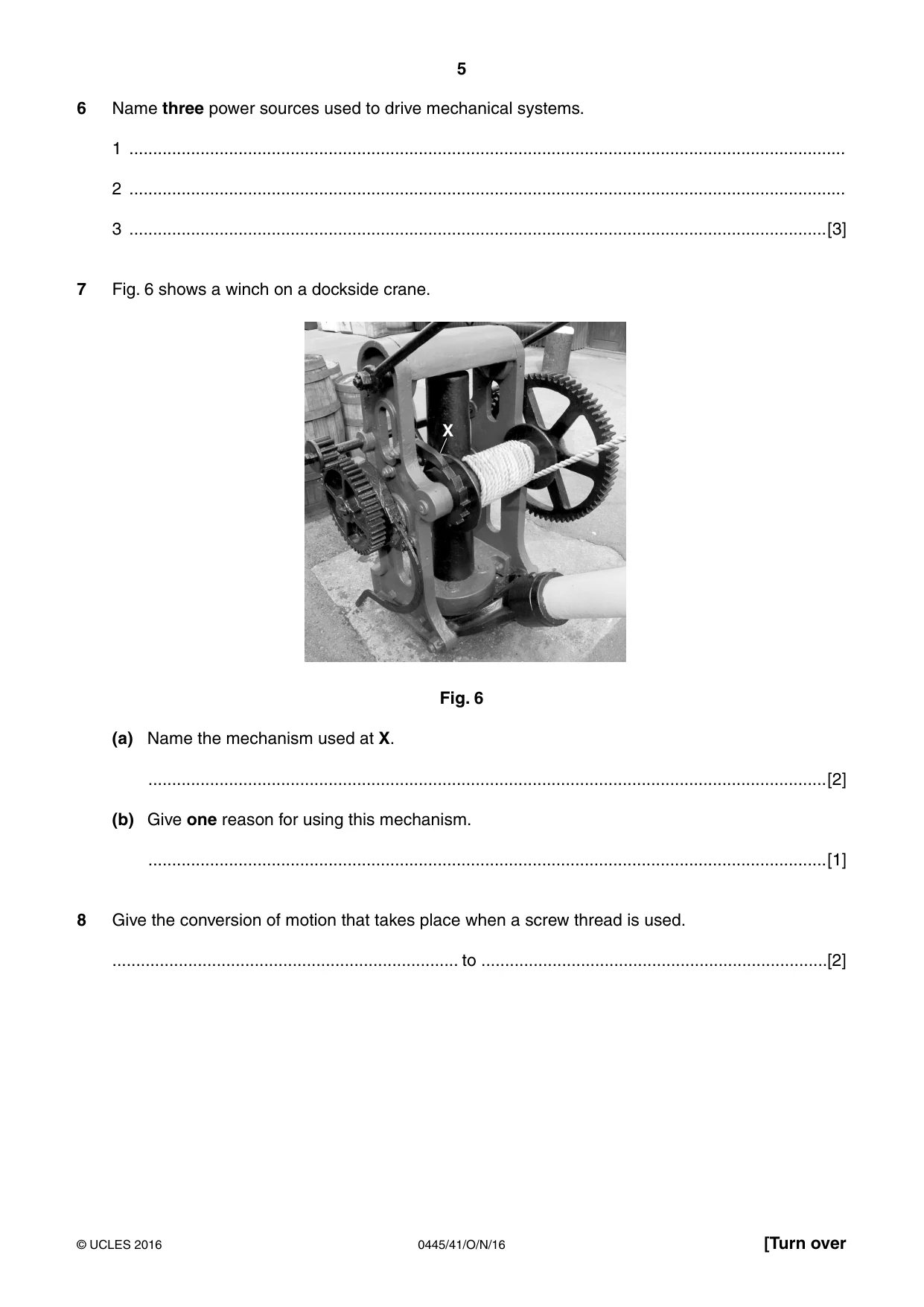
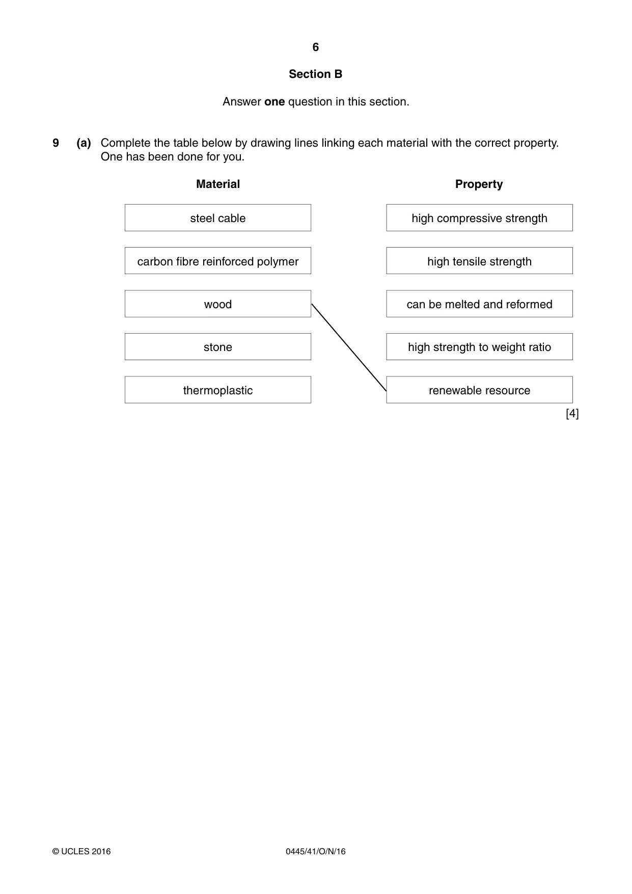
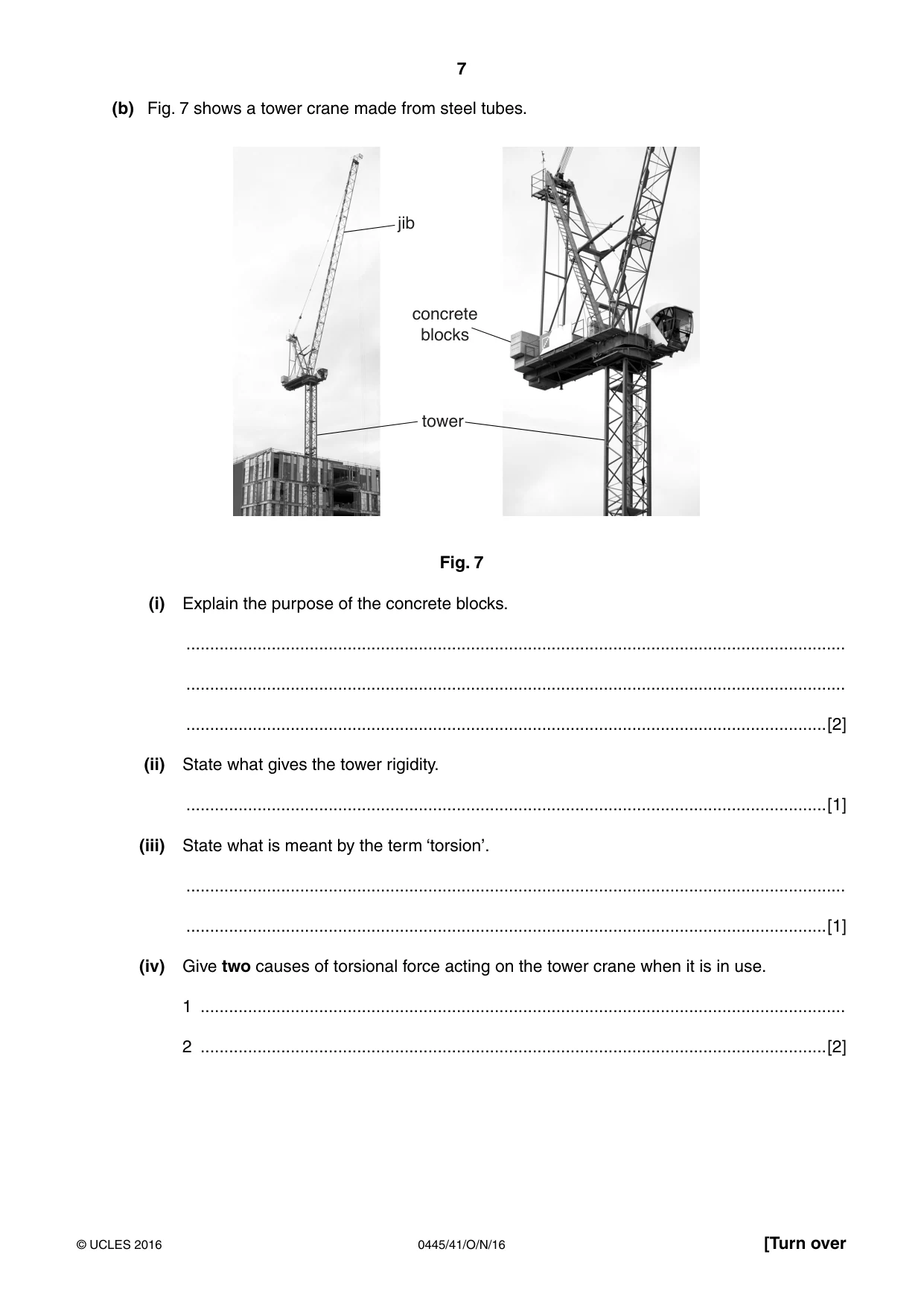
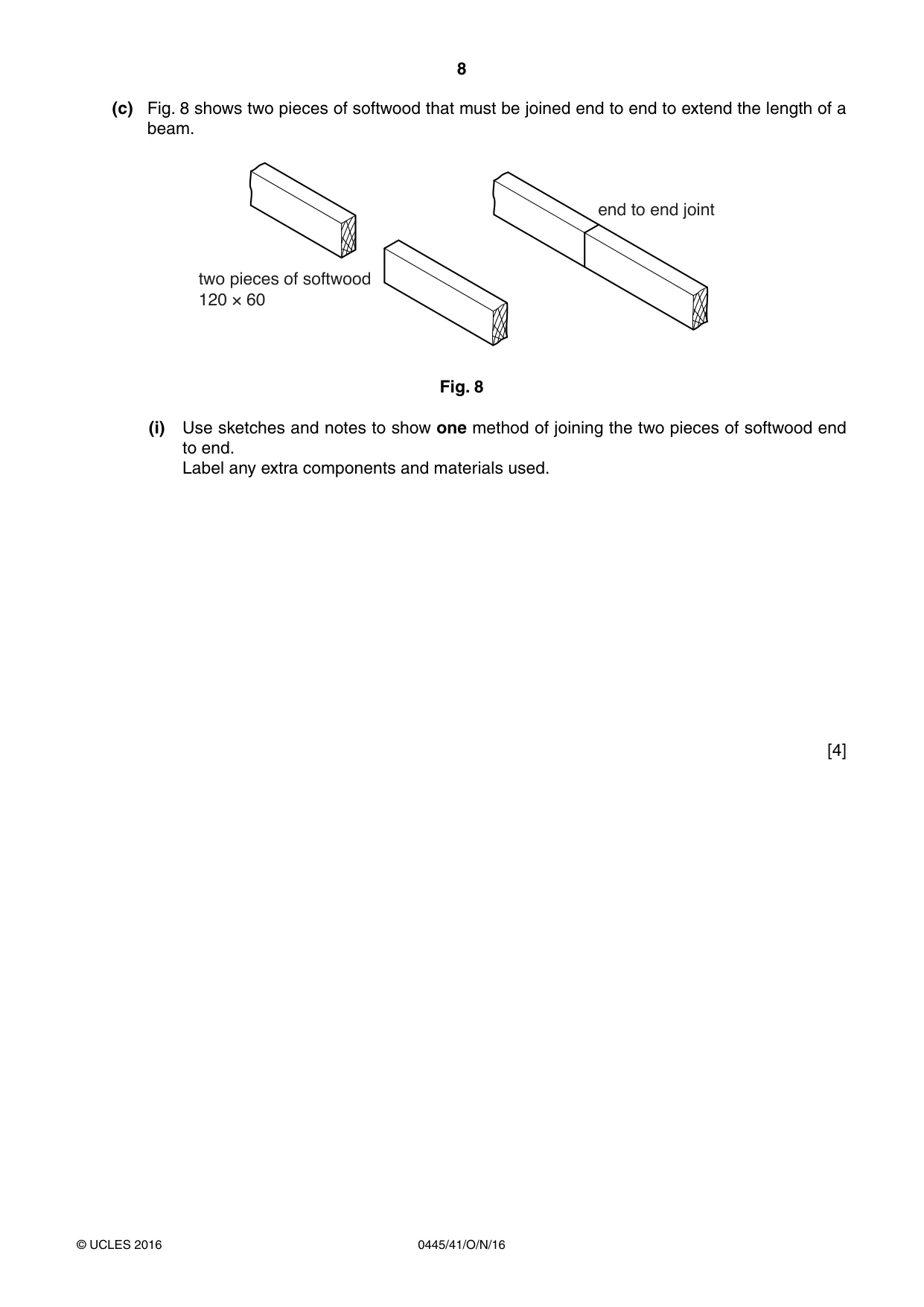
Mark scheme9 pages
Answers below. Sit the paper first if you are practising.
Paper as text
Question paper, page 1
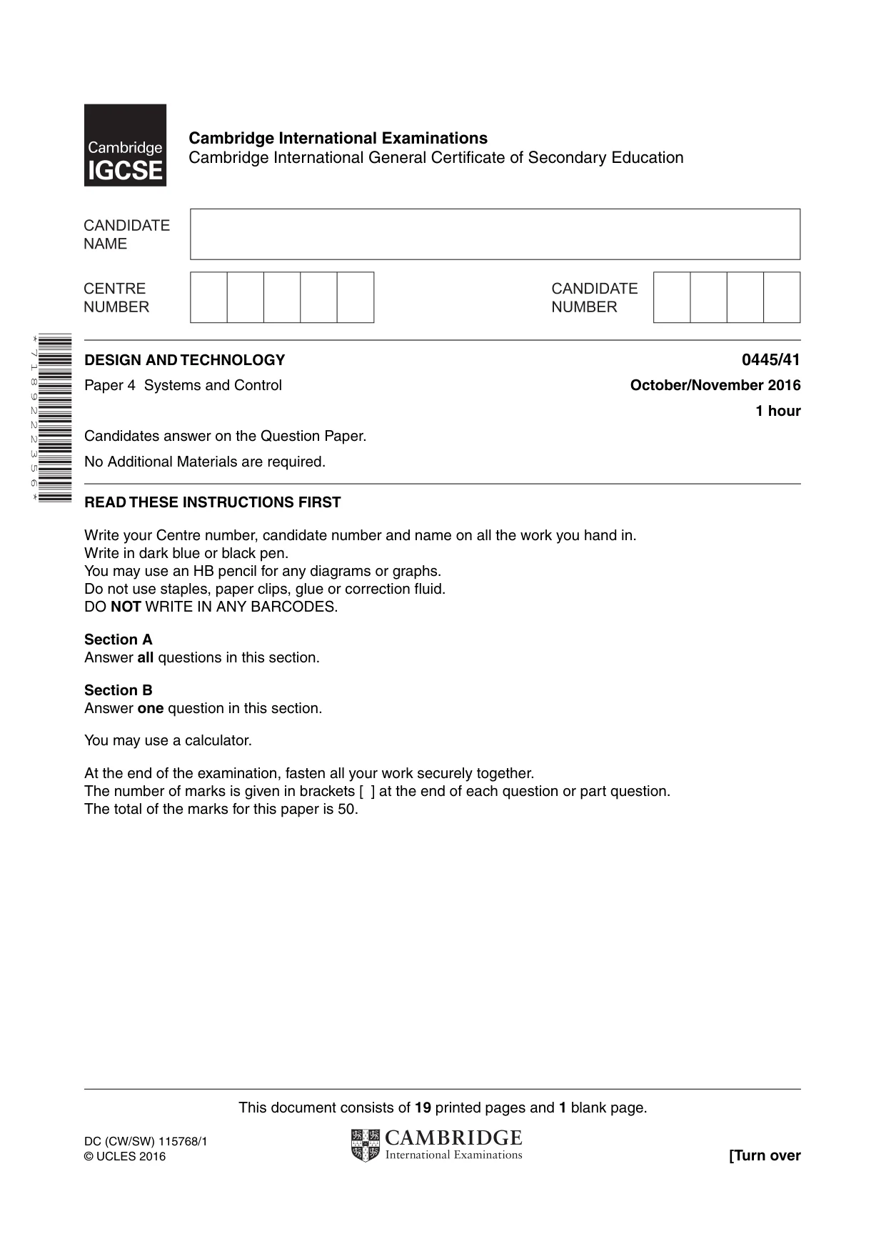
This document consists of 19 printed pages and 1 blank page. DC (CW/SW) 115768/1 © UCLES 2016 [Turn over Cambridge International Examinations Cambridge International General Certificate of Secondary Education * 7 1 8 9 2 2 2 3 5 6 * DESIGN AND TECHNOLOGY 0445/41 Paper 4 Systems and Control October/November 2016 1 hour Candidates answer on the Question Paper. No Additional Materials are required. READ THESE INSTRUCTIONS FIRST Write your Centre number, candidate number and name on all the work you hand in. Write in dark blue or black pen. You may use an HB pencil for any diagrams or graphs. Do not use staples, paper clips, glue or correction fluid. DO NOT WRITE IN ANY BARCODES. Section A Answer all questions in this section. Section B Answer one question in this section. You may use a calculator. At the end of the examination, fasten all your work securely together. The number of marks is given in brackets [ ] at the end of each question or part question. The total of the marks for this paper is 50.
Question paper, page 2
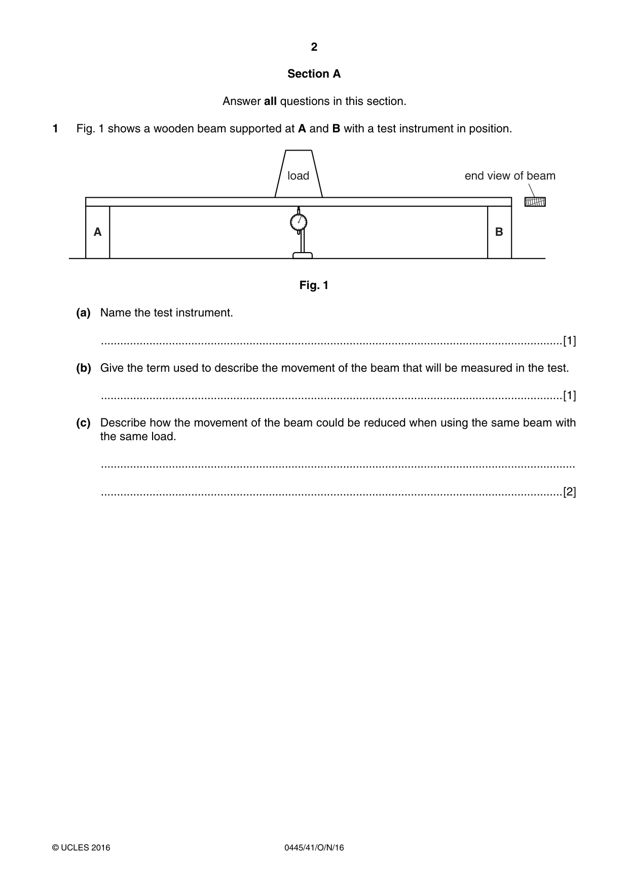
2 0445/41/O/N/16 © UCLES 2016 Section A Answer all questions in this section. 1 Fig. 1 shows a wooden beam supported at A and B with a test instrument in position. end view of beam load A B Fig. 1 (a) Name the test instrument. …[1] (b) Give the term used to describe the movement of the beam that will be measured in the test. …[1] (c) Describe how the movement of the beam could be reduced when using the same beam with the same load. … …[2]
Question paper, page 3
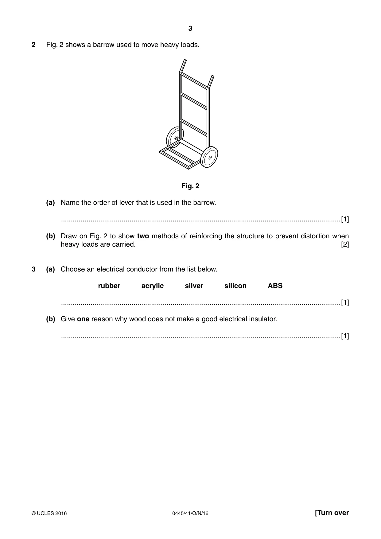
3 0445/41/O/N/16 © UCLES 2016 [Turn over 2 Fig. 2 shows a barrow used to move heavy loads. Fig. 2 (a) Name the order of lever that is used in the barrow. …[1] (b) Draw on Fig. 2 to show two methods of reinforcing the structure to prevent distortion when heavy loads are carried. [2] 3 (a) Choose an electrical conductor from the list below. rubber acrylic silver silicon ABS …[1] (b) Give one reason why wood does not make a good electrical insulator. …[1]
Question paper, page 4
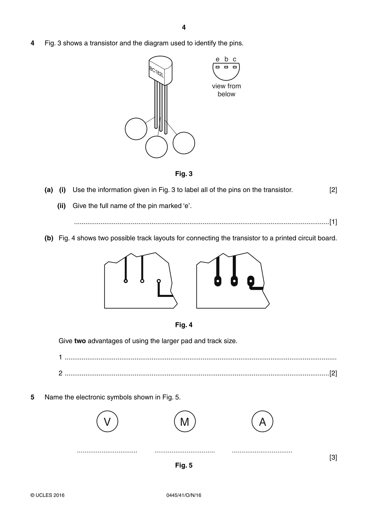
4 0445/41/O/N/16 © UCLES 2016 4 Fig. 3 shows a transistor and the diagram used to identify the pins. view from below e b c Fig. 3 (a) (i) Use the information given in Fig. 3 to label all of the pins on the transistor. [2] (ii) Give the full name of the pin marked ‘e’. …[1] (b) Fig. 4 shows two possible track layouts for connecting the transistor to a printed circuit board. Fig. 4 Give two advantages of using the larger pad and track size. 1 … 2 …[2] 5 Name the electronic symbols shown in Fig. 5. V … M … A … [3] Fig. 5
Question paper, page 5
5 0445/41/O/N/16 © UCLES 2016 [Turn over 6 Name three power sources used to drive mechanical systems. 1 … 2 … 3 …[3] 7 Fig. 6 shows a winch on a dockside crane. X Fig. 6 (a) Name the mechanism used at X. …[2] (b) Give one reason for using this mechanism. …[1] 8 Give the conversion of motion that takes place when a screw thread is used. … to …[2]
Question paper, page 6
6 0445/41/O/N/16 © UCLES 2016 Section B Answer one question in this section. 9 (a) Complete the table below by drawing lines linking each material with the correct property. One has been done for you. Material Property steel cable high compressive strength carbon fibre reinforced polymer high tensile strength wood can be melted and reformed stone high strength to weight ratio thermoplastic renewable resource [4]
Question paper, page 7
7 0445/41/O/N/16 © UCLES 2016 [Turn over (b) Fig. 7 shows a tower crane made from steel tubes. jib tower concrete blocks Fig. 7 (i) Explain the purpose of the concrete blocks. … … …[2] (ii) State what gives the tower rigidity. …[1] (iii) State what is meant by the term ‘torsion’. … …[1] (iv) Give two causes of torsional force acting on the tower crane when it is in use. 1 … 2 …[2]
Question paper, page 8
8 0445/41/O/N/16 © UCLES 2016 (c) Fig. 8 shows two pieces of softwood that must be joined end to end to extend the length of a beam. end to end joint two pieces of softwood 120 × 60 Fig. 8 (i) Use sketches and notes to show one method of joining the two pieces of softwood end to end. Label any extra components and materials used. [4]
Question paper, page 9
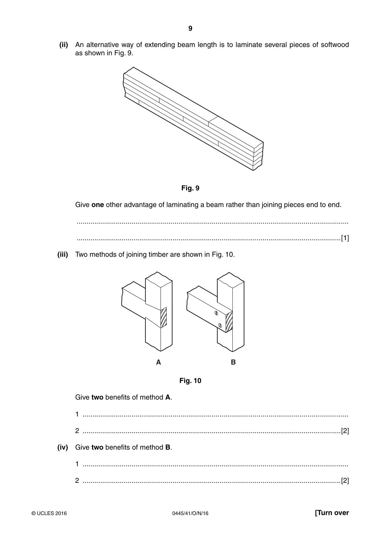
9 0445/41/O/N/16 © UCLES 2016 [Turn over (ii) An alternative way of extending beam length is to laminate several pieces of softwood as shown in Fig. 9. Fig. 9 Give one other advantage of laminating a beam rather than joining pieces end to end. … …[1] (iii) Two methods of joining timber are shown in Fig. 10. A B Fig. 10 Give two benefits of method A. 1 … 2 …[2] (iv) Give two benefits of method B. 1 … 2 …[2]
Question paper, page 10
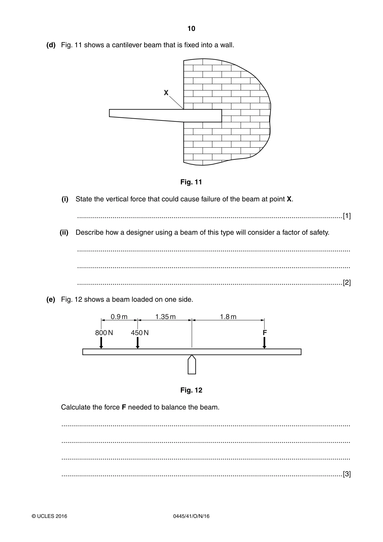
10 0445/41/O/N/16 © UCLES 2016 (d) Fig. 11 shows a cantilever beam that is fixed into a wall. X Fig. 11 (i) State the vertical force that could cause failure of the beam at point X. …[1] (ii) Describe how a designer using a beam of this type will consider a factor of safety. … … …[2] (e) Fig. 12 shows a beam loaded on one side. 0.9 m 800 N 450 N F 1.35 m 1.8 m Fig. 12 Calculate the force F needed to balance the beam. … … … …[3]
Question paper, page 11
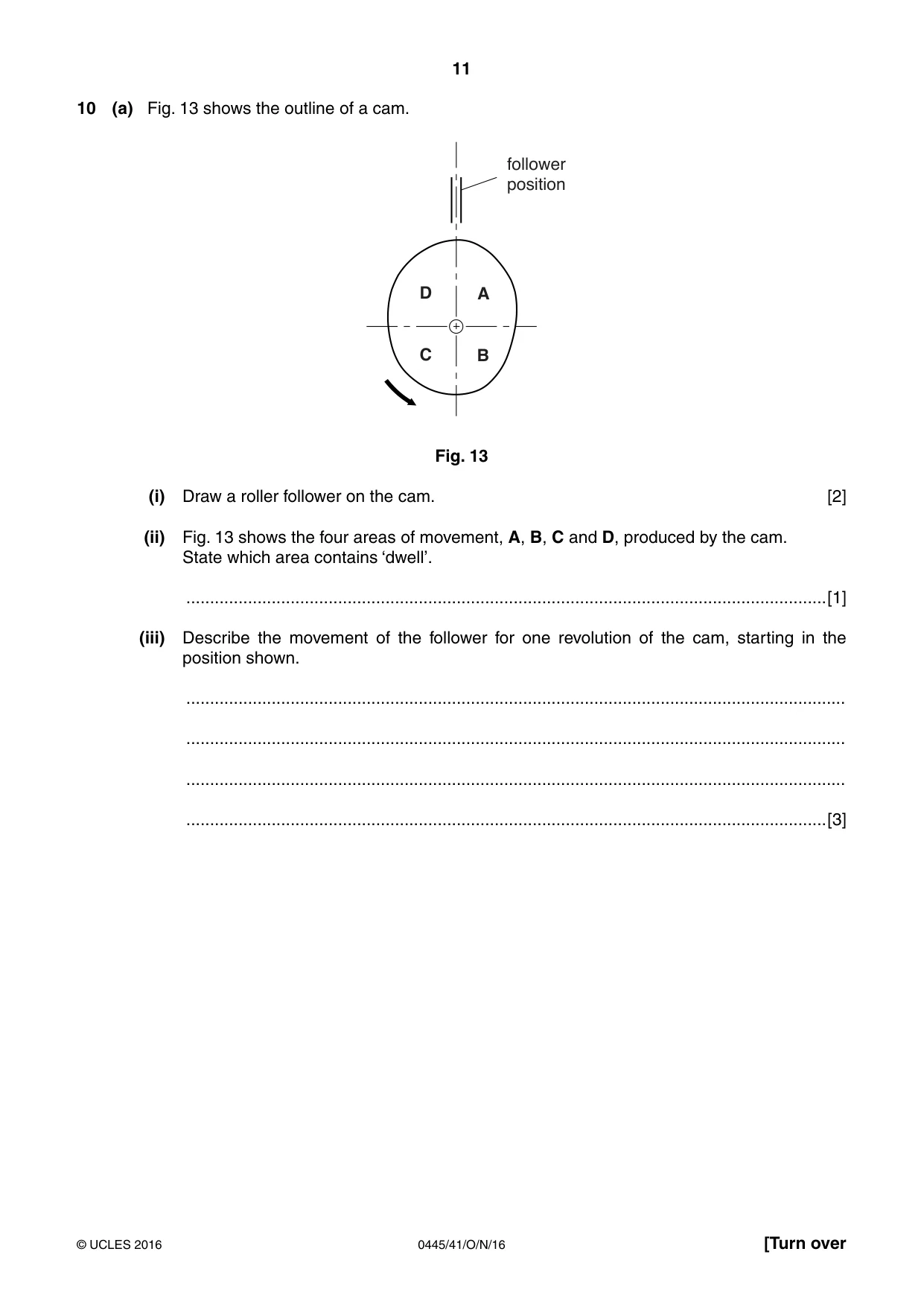
11 0445/41/O/N/16 © UCLES 2016 [Turn over 10 (a) Fig. 13 shows the outline of a cam. follower position D A C B Fig. 13 (i) Draw a roller follower on the cam. [2] (ii) Fig. 13 shows the four areas of movement, A, B, C and D, produced by the cam. State which area contains ‘dwell’. …[1] (iii) Describe the movement of the follower for one revolution of the cam, starting in the position shown. … … … …[3]
Question paper, page 12
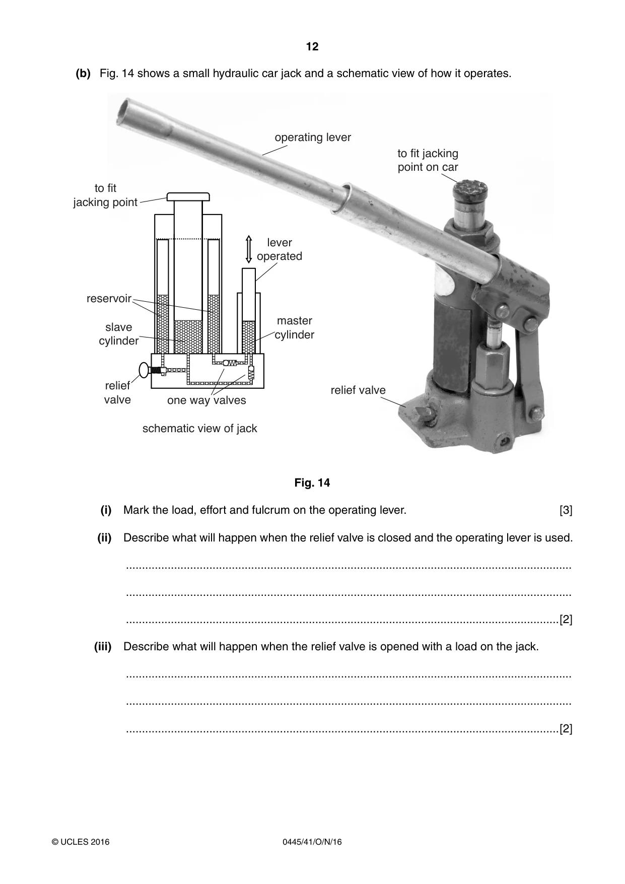
12 0445/41/O/N/16 © UCLES 2016 (b) Fig. 14 shows a small hydraulic car jack and a schematic view of how it operates. master cylinder lever operated operating lever to fit jacking point on car relief valve to fit jacking point reservoir slave cylinder relief valve one way valves schematic view of jack Fig. 14 (i) Mark the load, effort and fulcrum on the operating lever. [3] (ii) Describe what will happen when the relief valve is closed and the operating lever is used. … … …[2] (iii) Describe what will happen when the relief valve is opened with a load on the jack. … … …[2]
Question paper, page 13
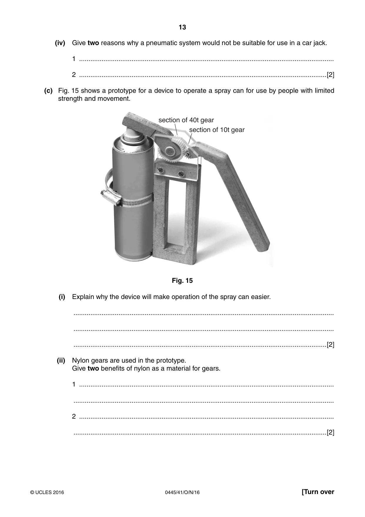
13 0445/41/O/N/16 © UCLES 2016 [Turn over (iv) Give two reasons why a pneumatic system would not be suitable for use in a car jack. 1 … 2 …[2] (c) Fig. 15 shows a prototype for a device to operate a spray can for use by people with limited strength and movement. section of 40t gear section of 10t gear Fig. 15 (i) Explain why the device will make operation of the spray can easier. … … …[2] (ii) Nylon gears are used in the prototype. Give two benefits of nylon as a material for gears. 1 … … 2 … …[2]
Question paper, page 14
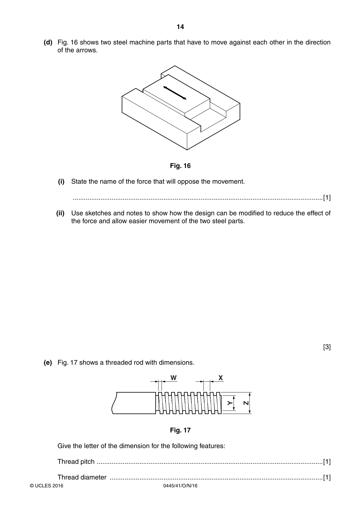
14 0445/41/O/N/16 © UCLES 2016 (d) Fig. 16 shows two steel machine parts that have to move against each other in the direction of the arrows. Fig. 16 (i) State the name of the force that will oppose the movement. …[1] (ii) Use sketches and notes to show how the design can be modified to reduce the effect of the force and allow easier movement of the two steel parts. [3] (e) Fig. 17 shows a threaded rod with dimensions. W X Y Z Fig. 17 Give the letter of the dimension for the following features: Thread pitch …[1] Thread diameter …[1]
Question paper, page 15
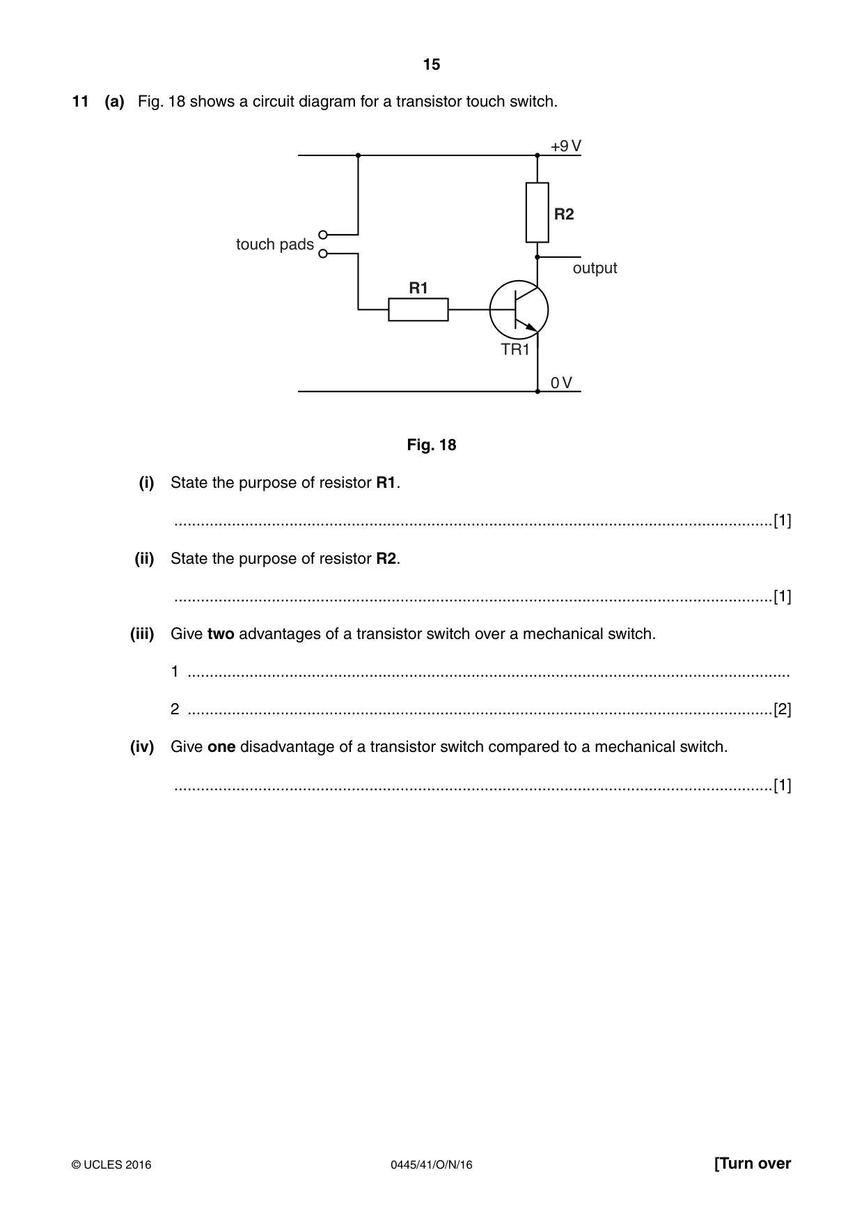
15 0445/41/O/N/16 © UCLES 2016 [Turn over 11 (a) Fig. 18 shows a circuit diagram for a transistor touch switch. +9 V 0 V TR1 output touch pads R2 R1 Fig. 18 (i) State the purpose of resistor R1. …[1] (ii) State the purpose of resistor R2. …[1] (iii) Give two advantages of a transistor switch over a mechanical switch. 1 … 2 …[2] (iv) Give one disadvantage of a transistor switch compared to a mechanical switch. …[1]
Question paper, page 16
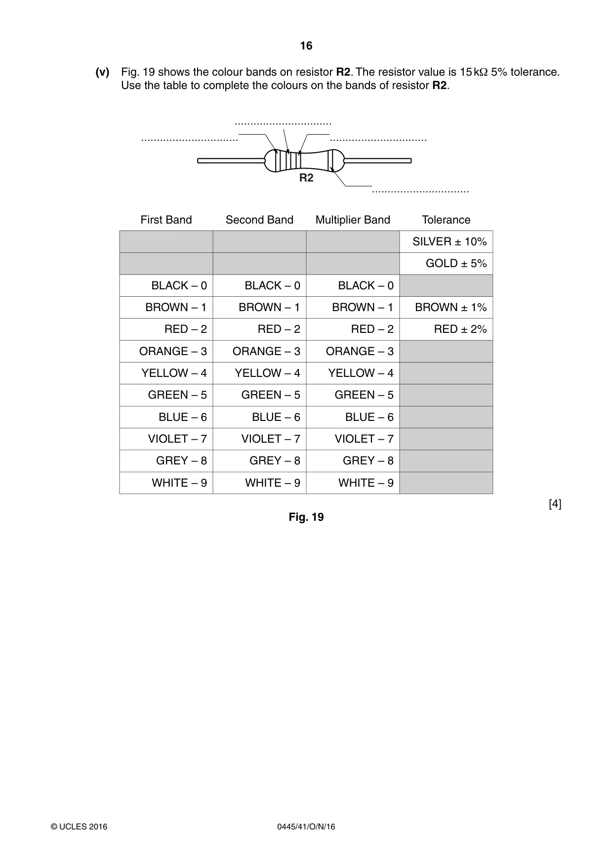
16 0445/41/O/N/16 © UCLES 2016 (v) Fig. 19 shows the colour bands on resistor R2. The resistor value is 15 kΩ 5% tolerance. Use the table to complete the colours on the bands of resistor R2. R2 … … … … First Band Second Band Multiplier Band Tolerance SILVER ± 10% GOLD ± 5% BLACK – 0 BLACK – 0 BLACK – 0 BROWN – 1 BROWN – 1 BROWN – 1 BROWN ± 1% RED – 2 RED – 2 RED – 2 RED ± 2% ORANGE – 3 ORANGE – 3 ORANGE – 3 YELLOW – 4 YELLOW – 4 YELLOW – 4 GREEN – 5 GREEN – 5 GREEN – 5 BLUE – 6 BLUE – 6 BLUE – 6 VIOLET – 7 VIOLET – 7 VIOLET – 7 GREY – 8 GREY – 8 GREY – 8 WHITE – 9 WHITE – 9 WHITE – 9 [4] Fig. 19
Question paper, page 17
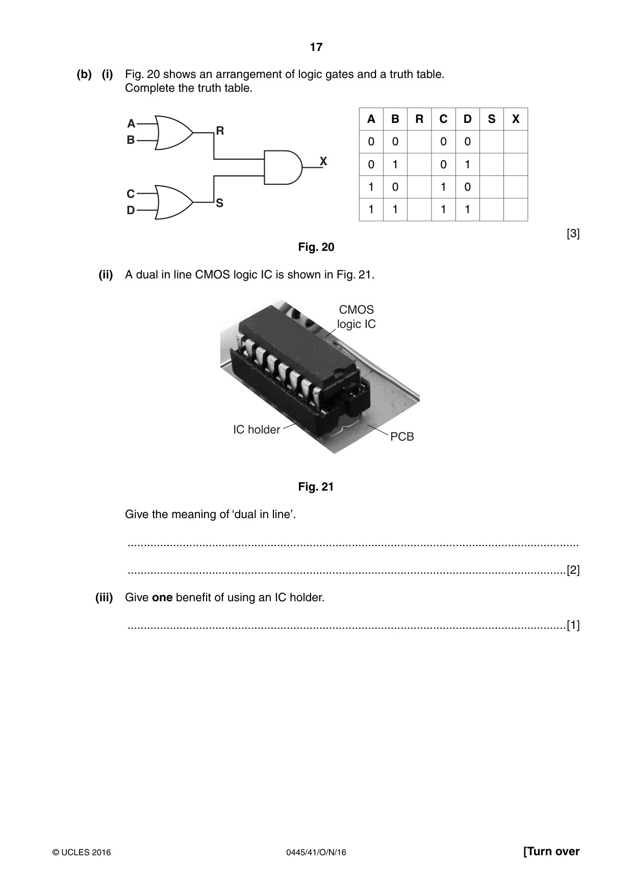
17 0445/41/O/N/16 © UCLES 2016 [Turn over (b) (i) Fig. 20 shows an arrangement of logic gates and a truth table. Complete the truth table. A R S X B C D A B R C D S X 0 0 0 0 0 1 0 1 1 0 1 0 1 1 1 1 [3] Fig. 20 (ii) A dual in line CMOS logic IC is shown in Fig. 21. CMOS logic IC PCB IC holder Fig. 21 Give the meaning of ‘dual in line’. … …[2] (iii) Give one benefit of using an IC holder. …[1]
Question paper, page 18
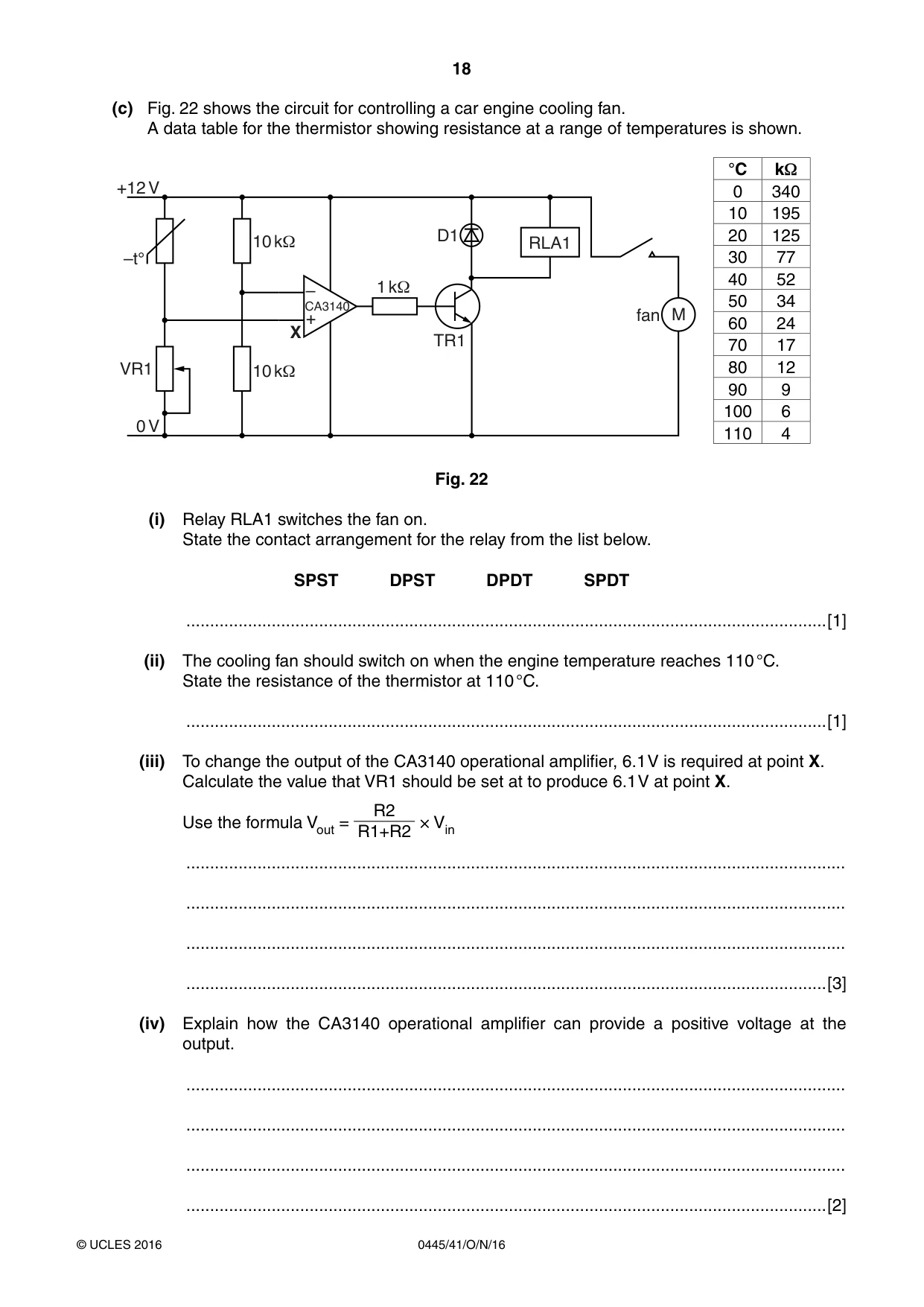
18 0445/41/O/N/16 © UCLES 2016 (c) Fig. 22 shows the circuit for controlling a car engine cooling fan. A data table for the thermistor showing resistance at a range of temperatures is shown. M D1 TR1 1 k1 CA3140 – + 10 k1 10 k1 RLA1 fan X +12 V 0 V VR1 –t° °C kΩ 0 340 10 195 20 125 30 77 40 52 50 34 60 24 70 17 80 12 90 9 100 6 110 4 Fig. 22 (i) Relay RLA1 switches the fan on. State the contact arrangement for the relay from the list below. SPST DPST DPDT SPDT …[1] (ii) The cooling fan should switch on when the engine temperature reaches 110 °C. State the resistance of the thermistor at 110 °C. …[1] (iii) To change the output of the CA3140 operational amplifier, 6.1 V is required at point X. Calculate the value that VR1 should be set at to produce 6.1 V at point X. Use the formula Vout = R2 R1+R2 × Vin … … … …[3] (iv) Explain how the CA3140 operational amplifier can provide a positive voltage at the output. … … … …[2]
Question paper, page 19
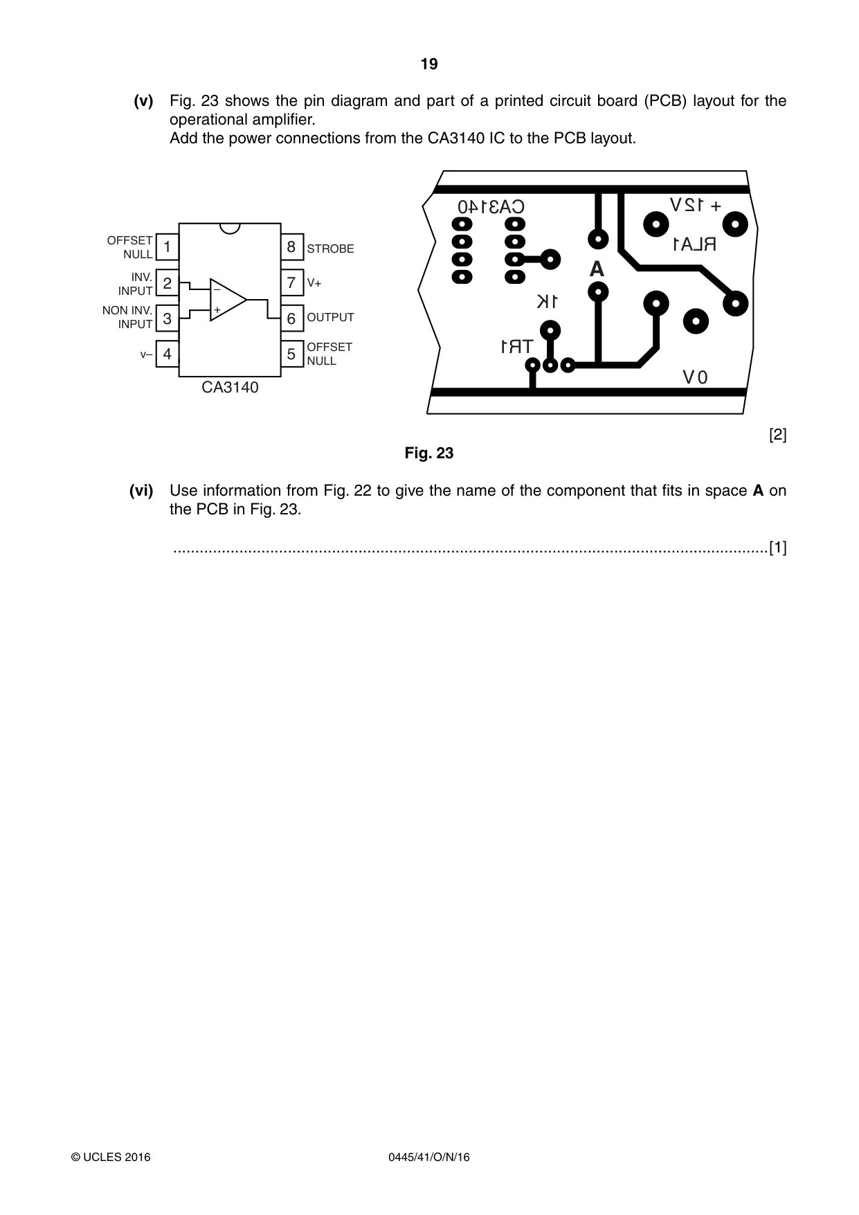
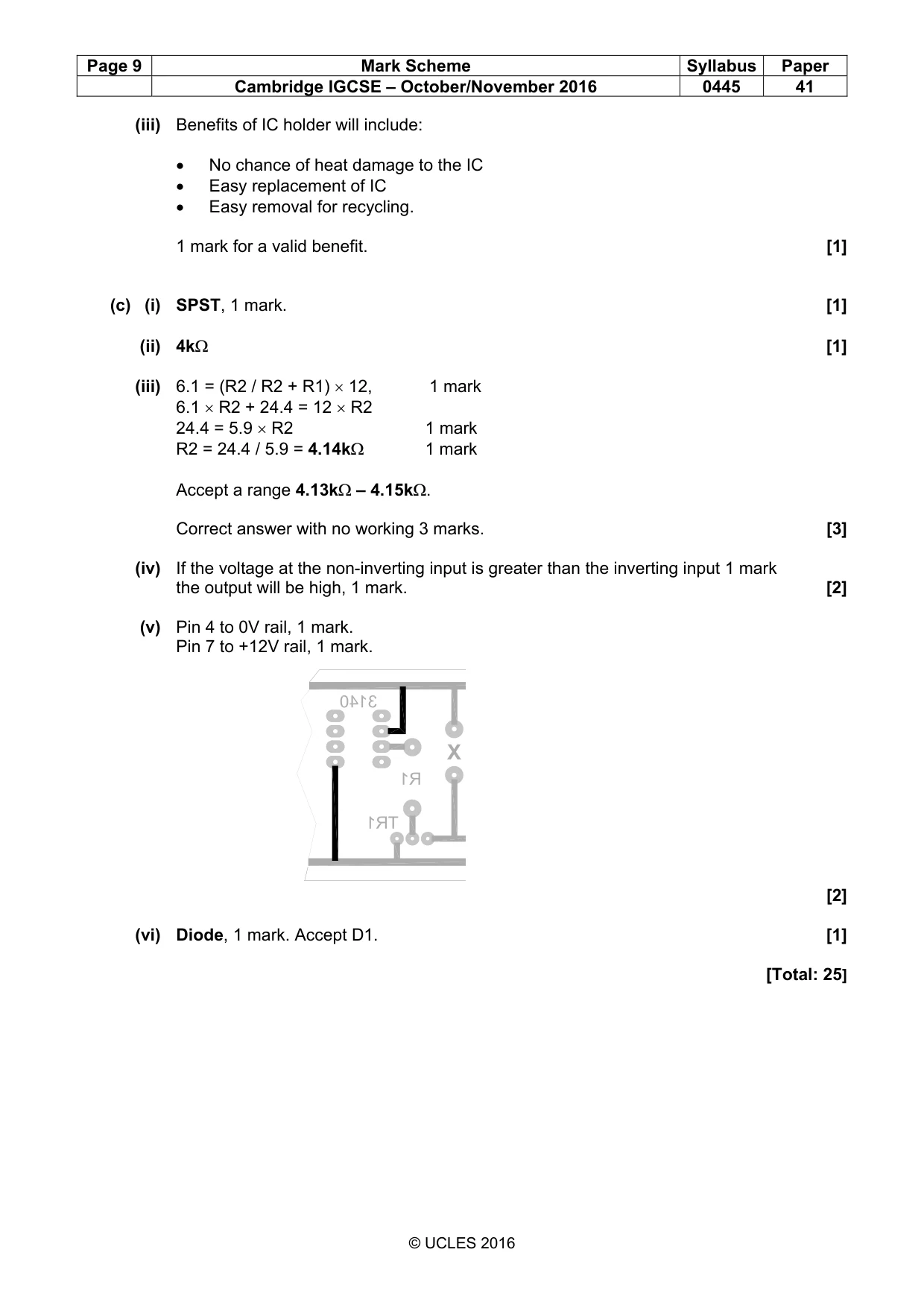
19 0445/41/O/N/16 © UCLES 2016 (v) Fig. 23 shows the pin diagram and part of a printed circuit board (PCB) layout for the operational amplifier. Add the power connections from the CA3140 IC to the PCB layout. 1 OFFSET NULL STROBE V+ OUTPUT CA3140 – + OFFSET NULL INV. INPUT NON INV. INPUT v– 2 3 4 5 6 7 8 TR1 0 V + 12 V RLA1 A 1K CA3140 [2] Fig. 23 (vi) Use information from Fig. 22 to give the name of the component that fits in space A on the PCB in Fig. 23. …[1]
Question paper, page 20
20 0445/41/O/N/16 © UCLES 2016 BLANK PAGE Permission to reproduce items where third-party owned material protected by copyright is included has been sought and cleared where possible. Every reasonable effort has been made by the publisher (UCLES) to trace copyright holders, but if any items requiring clearance have unwittingly been included, the publisher will be pleased to make amends at the earliest possible opportunity. To avoid the issue of disclosure of answer-related information to candidates, all copyright acknowledgements are reproduced online in the Cambridge International Examinations Copyright Acknowledgements Booklet. This is produced for each series of examinations and is freely available to download at www.cie.org.uk after the live examination series. Cambridge International Examinations is part of the Cambridge Assessment Group. Cambridge Assessment is the brand name of University of Cambridge Local Examinations Syndicate (UCLES), which is itself a department of the University of Cambridge.
Mark scheme, page 1
® IGCSE is the registered trademark of Cambridge International Examinations. This document consists of 9 printed pages. © UCLES 2016 [Turn over Cambridge International Examinations Cambridge International General Certificate of Secondary Education DESIGN AND TECHNOLOGY 0445/41 Paper 4 Systems and Control October/November 2016 MARK SCHEME Maximum Mark: 50 Published This mark scheme is published as an aid to teachers and candidates, to indicate the requirements of the examination. It shows the basis on which Examiners were instructed to award marks. It does not indicate the details of the discussions that took place at an Examiners’ meeting before marking began, which would have considered the acceptability of alternative answers. Mark schemes should be read in conjunction with the question paper and the Principal Examiner Report for Teachers. Cambridge will not enter into discussions about these mark schemes. Cambridge is publishing the mark schemes for the October/November 2016 series for most Cambridge IGCSE®, Cambridge International A and AS Level components and some Cambridge O Level components.
Mark scheme, page 2
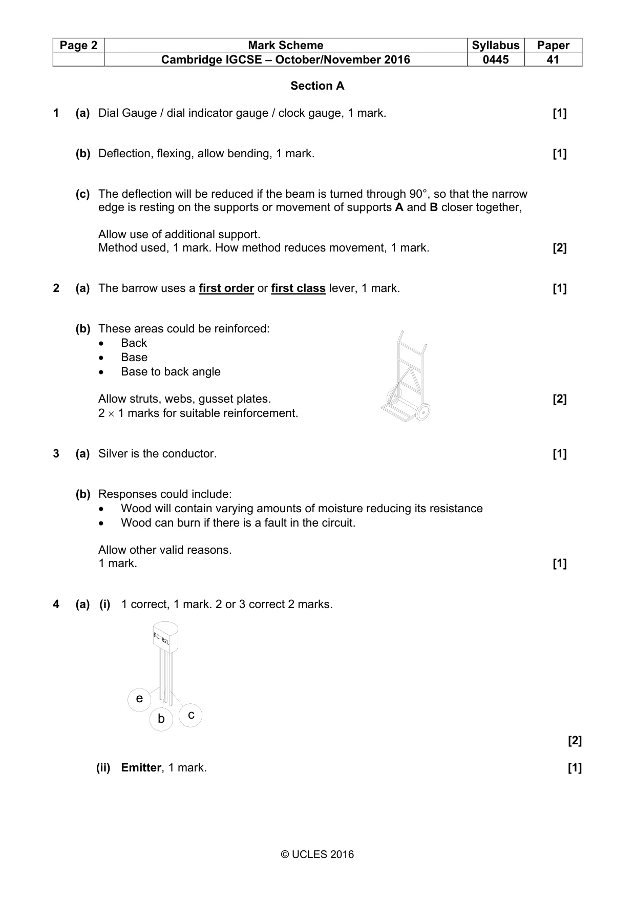
Page 2 Mark Scheme Syllabus Paper Cambridge IGCSE – October/November 2016 0445 41 © UCLES 2016 Section A 1 (a) Dial Gauge / dial indicator gauge / clock gauge, 1 mark. [1] (b) Deflection, flexing, allow bending, 1 mark. [1] (c) The deflection will be reduced if the beam is turned through 90°, so that the narrow edge is resting on the supports or movement of supports A and B closer together, Allow use of additional support. Method used, 1 mark. How method reduces movement, 1 mark. [2] 2 (a) The barrow uses a first order or first class lever, 1 mark. [1] (b) These areas could be reinforced: • Back • Base • Base to back angle Allow struts, webs, gusset plates. [2] 2 × 1 marks for suitable reinforcement. 3 (a) Silver is the conductor. [1] (b) Responses could include: • Wood will contain varying amounts of moisture reducing its resistance • Wood can burn if there is a fault in the circuit. Allow other valid reasons. 1 mark. [1] 4 (a) (i) 1 correct, 1 mark. 2 or 3 correct 2 marks. [2] (ii) Emitter, 1 mark. [1] e b c
Mark scheme, page 3
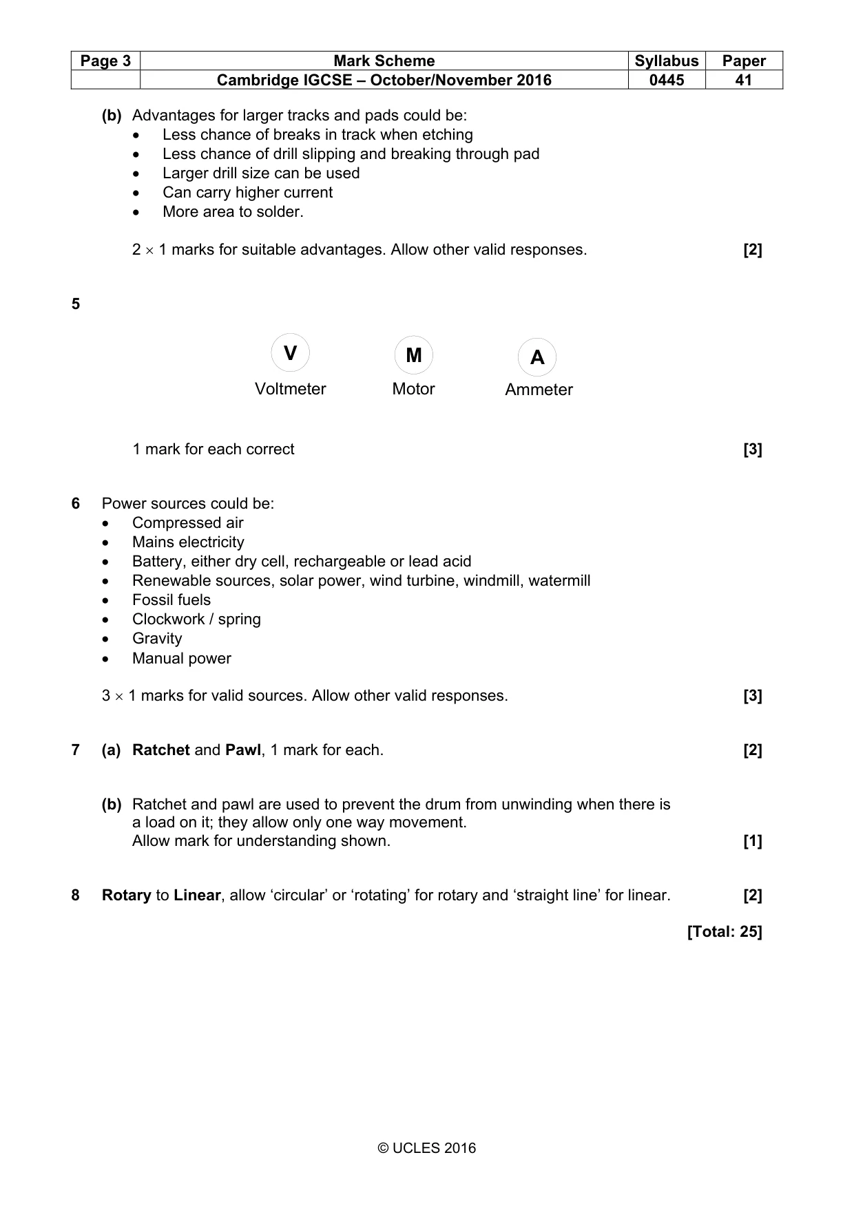
Page 3 Mark Scheme Syllabus Paper Cambridge IGCSE – October/November 2016 0445 41 © UCLES 2016 (b) Advantages for larger tracks and pads could be: • Less chance of breaks in track when etching • Less chance of drill slipping and breaking through pad • Larger drill size can be used • Can carry higher current • More area to solder. 2 × 1 marks for suitable advantages. Allow other valid responses. [2] 5 1 mark for each correct [3] 6 Power sources could be: • Compressed air • Mains electricity • Battery, either dry cell, rechargeable or lead acid • Renewable sources, solar power, wind turbine, windmill, watermill • Fossil fuels • Clockwork / spring • Gravity • Manual power 3 × 1 marks for valid sources. Allow other valid responses. [3] 7 (a) Ratchet and Pawl, 1 mark for each. [2] (b) Ratchet and pawl are used to prevent the drum from unwinding when there is a load on it; they allow only one way movement. Allow mark for understanding shown. [1] 8 Rotary to Linear, allow ‘circular’ or ‘rotating’ for rotary and ‘straight line’ for linear. [2] [Total: 25] V M A Voltmeter Motor Ammeter
Mark scheme, page 4
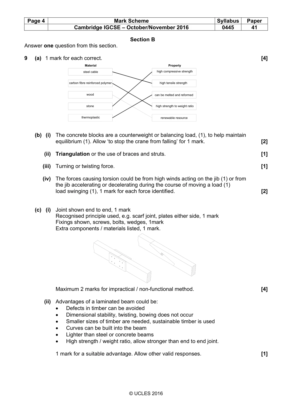
Page 4 Mark Scheme Syllabus Paper Cambridge IGCSE – October/November 2016 0445 41 © UCLES 2016 Section B Answer one question from this section. 9 (a) 1 mark for each correct. [4] (b) (i) The concrete blocks are a counterweight or balancing load, (1), to help maintain equilibrium (1). Allow ‘to stop the crane from falling’ for 1 mark. [2] (ii) Triangulation or the use of braces and struts. [1] (iii) Turning or twisting force. [1] (iv) The forces causing torsion could be from high winds acting on the jib (1) or from the jib accelerating or decelerating during the course of moving a load (1) load swinging (1), 1 mark for each force identified. [2] (c) (i) Joint shown end to end, 1 mark Recognised principle used, e.g. scarf joint, plates either side, 1 mark Fixings shown, screws, bolts, wedges, 1mark Extra components / materials listed, 1 mark. Maximum 2 marks for impractical / non-functional method. [4] (ii) Advantages of a laminated beam could be: • Defects in timber can be avoided • Dimensional stability, twisting, bowing does not occur • Smaller sizes of timber are needed, sustainable timber is used • Curves can be built into the beam • Lighter than steel or concrete beams • High strength / weight ratio, allow stronger than end to end joint. 1 mark for a suitable advantage. Allow other valid responses. [1] steel cable carbon fibre reinforced polymer wood stone thermoplastic high compressive strength high tensile strength can be melted and reformed high strength to weight ratio renewable resource Material Property
Mark scheme, page 5
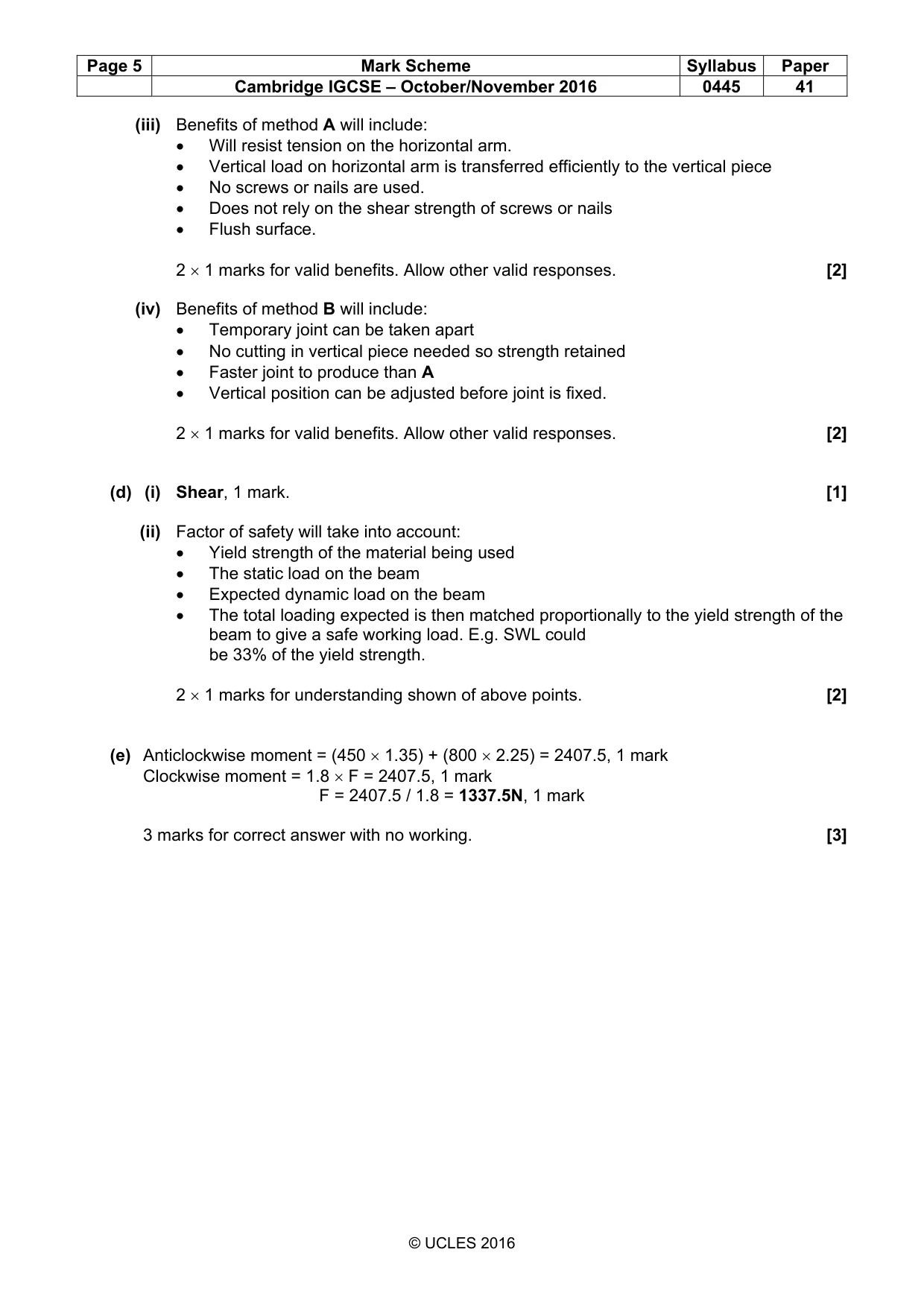
Page 5 Mark Scheme Syllabus Paper Cambridge IGCSE – October/November 2016 0445 41 © UCLES 2016 (iii) Benefits of method A will include: • Will resist tension on the horizontal arm. • Vertical load on horizontal arm is transferred efficiently to the vertical piece • No screws or nails are used. • Does not rely on the shear strength of screws or nails • Flush surface. 2 × 1 marks for valid benefits. Allow other valid responses. [2] (iv) Benefits of method B will include: • Temporary joint can be taken apart • No cutting in vertical piece needed so strength retained • Faster joint to produce than A • Vertical position can be adjusted before joint is fixed. 2 × 1 marks for valid benefits. Allow other valid responses. [2] (d) (i) Shear, 1 mark. [1] (ii) Factor of safety will take into account: • Yield strength of the material being used • The static load on the beam • Expected dynamic load on the beam • The total loading expected is then matched proportionally to the yield strength of the beam to give a safe working load. E.g. SWL could be 33% of the yield strength. 2 × 1 marks for understanding shown of above points. [2] (e) Anticlockwise moment = (450 × 1.35) + (800 × 2.25) = 2407.5, 1 mark Clockwise moment = 1.8 × F = 2407.5, 1 mark F = 2407.5 / 1.8 = 1337.5N, 1 mark 3 marks for correct answer with no working. [3]
Mark scheme, page 6
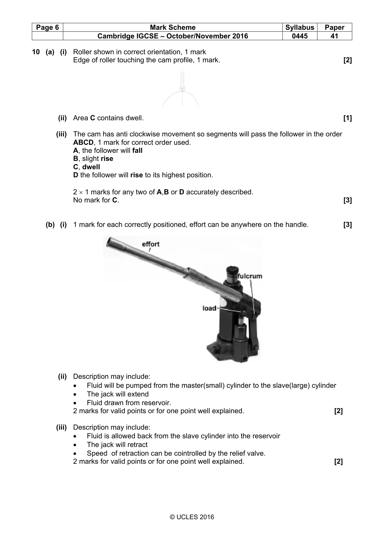
Page 6 Mark Scheme Syllabus Paper Cambridge IGCSE – October/November 2016 0445 41 © UCLES 2016 10 (a) (i) Roller shown in correct orientation, 1 mark Edge of roller touching the cam profile, 1 mark. [2] (ii) Area C contains dwell. [1] (iii) The cam has anti clockwise movement so segments will pass the follower in the order ABCD, 1 mark for correct order used. A, the follower will fall B, slight rise C, dwell D the follower will rise to its highest position. 2 × 1 marks for any two of A,B or D accurately described. No mark for C. [3] (b) (i) 1 mark for each correctly positioned, effort can be anywhere on the handle. [3] (ii) Description may include: • Fluid will be pumped from the master(small) cylinder to the slave(large) cylinder • The jack will extend • Fluid drawn from reservoir. 2 marks for valid points or for one point well explained. [2] (iii) Description may include: • Fluid is allowed back from the slave cylinder into the reservoir • The jack will retract • Speed of retraction can be cointrolled by the relief valve. 2 marks for valid points or for one point well explained. [2]
Mark scheme, page 7
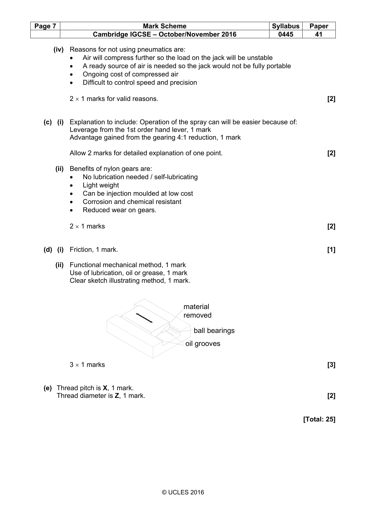
Page 7 Mark Scheme Syllabus Paper Cambridge IGCSE – October/November 2016 0445 41 © UCLES 2016 (iv) Reasons for not using pneumatics are: • Air will compress further so the load on the jack will be unstable • A ready source of air is needed so the jack would not be fully portable • Ongoing cost of compressed air • Difficult to control speed and precision 2 × 1 marks for valid reasons. [2] (c) (i) Explanation to include: Operation of the spray can will be easier because of: Leverage from the 1st order hand lever, 1 mark Advantage gained from the gearing 4:1 reduction, 1 mark Allow 2 marks for detailed explanation of one point. [2] (ii) Benefits of nylon gears are: • No lubrication needed / self-lubricating • Light weight • Can be injection moulded at low cost • Corrosion and chemical resistant • Reduced wear on gears. 2 × 1 marks [2] (d) (i) Friction, 1 mark. [1] (ii) Functional mechanical method, 1 mark Use of lubrication, oil or grease, 1 mark Clear sketch illustrating method, 1 mark. 3 × 1 marks [3] (e) Thread pitch is X, 1 mark. Thread diameter is Z, 1 mark. [2] [Total: 25] oil grooves material removed ball bearings
Mark scheme, page 8
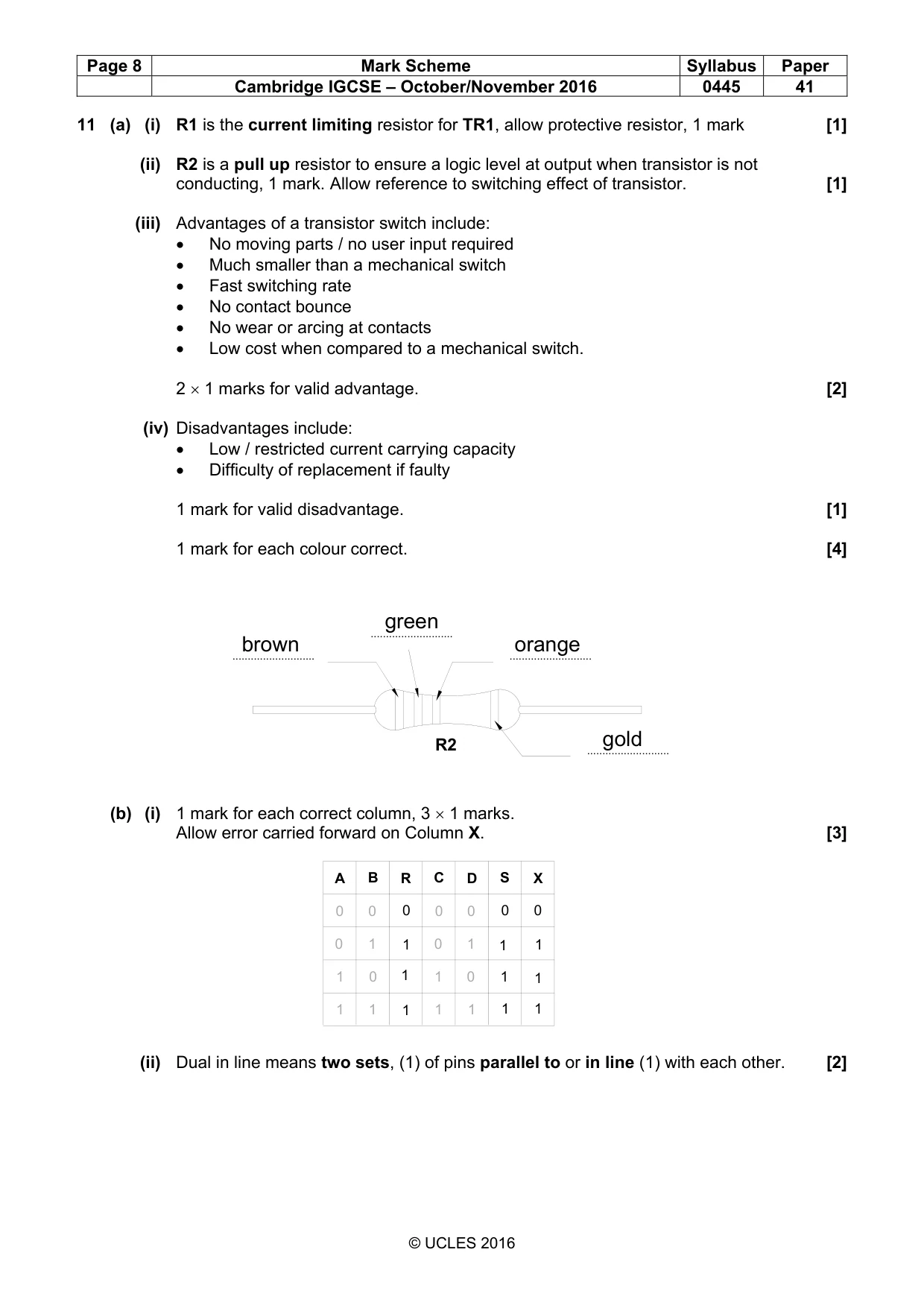
Page 8 Mark Scheme Syllabus Paper Cambridge IGCSE – October/November 2016 0445 41 © UCLES 2016 11 (a) (i) R1 is the current limiting resistor for TR1, allow protective resistor, 1 mark [1] (ii) R2 is a pull up resistor to ensure a logic level at output when transistor is not conducting, 1 mark. Allow reference to switching effect of transistor. [1] (iii) Advantages of a transistor switch include: • No moving parts / no user input required • Much smaller than a mechanical switch • Fast switching rate • No contact bounce • No wear or arcing at contacts • Low cost when compared to a mechanical switch. 2 × 1 marks for valid advantage. [2] (iv) Disadvantages include: • Low / restricted current carrying capacity • Difficulty of replacement if faulty 1 mark for valid disadvantage. [1] 1 mark for each colour correct. [4] (b) (i) 1 mark for each correct column, 3 × 1 marks. Allow error carried forward on Column X. [3] (ii) Dual in line means two sets, (1) of pins parallel to or in line (1) with each other. [2] … … … … R2 brown green orange gold A B C D R S X 0 0 0 0 0 0 1 1 1 1 0 0 1 1 1 1 1 1 1 1 1 1 1 1 1 0 0 0
Mark scheme, page 9
Page 9 Mark Scheme Syllabus Paper Cambridge IGCSE – October/November 2016 0445 41 © UCLES 2016 (iii) Benefits of IC holder will include: • No chance of heat damage to the IC • Easy replacement of IC • Easy removal for recycling. 1 mark for a valid benefit. [1] (c) (i) SPST, 1 mark. [1] (ii) 4kΩ [1] (iii) 6.1 = (R2 / R2 + R1) × 12, 1 mark 6.1 × R2 + 24.4 = 12 × R2 24.4 = 5.9 × R2 1 mark R2 = 24.4 / 5.9 = 4.14kΩ 1 mark Accept a range 4.13kΩ – 4.15kΩ. Correct answer with no working 3 marks. [3] (iv) If the voltage at the non-inverting input is greater than the inverting input 1 mark the output will be high, 1 mark. [2] (v) Pin 4 to 0V rail, 1 mark. Pin 7 to +12V rail, 1 mark. [2] (vi) Diode, 1 mark. Accept D1. [1] [Total: 25] X
What you needed in this session
Cambridge’s own grade thresholds for 2016 Oct/Nov, Paper 4 · Variant 1. A higher threshold means an easier paper — the bar moves with how the cohort did.