Cambridge IGCSE Design and Technology 0445 — 2015 Oct/Nov Paper 4 · Variant 3
0445/43/O/N/15 · 50 marks · ≈56 min
The question paper and its mark scheme, free to read here and free to download. This is Cambridge’s own paper, exactly as it was sat.
Question paper20 pages


Mark scheme10 pages
Answers below. Sit the paper first if you are practising.
Paper as text
Question paper, page 1
This document consists of 17 printed pages and 3 blank pages. DC (ST/CGW) 107899 © UCLES 2015 [Turn over Cambridge International Examinations Cambridge International General Certificate of Secondary Education * 6 2 6 6 0 7 3 7 4 8 * DESIGN AND TECHNOLOGY 0445/43 Paper 4 Systems and Control October/November 2015 1 hour Candidates answer on the Question Paper. No Additional Materials are required. READ THESE INSTRUCTIONS FIRST Write your Centre number, candidate number and name on all the work you hand in. Write in dark blue or black pen. You may use an HB pencil for any diagrams or graphs. Do not use staples, paper clips, glue or correction fluid. DO NOT WRITE IN ANY BARCODES. Section A Answer all questions in this section. Section B Answer one question in this section. You may use a calculator. At the end of the examination, fasten all your work securely together. The number of marks is given in brackets [ ] at the end of each question or part question. The total of the marks for this paper is 50.
Question paper, page 2
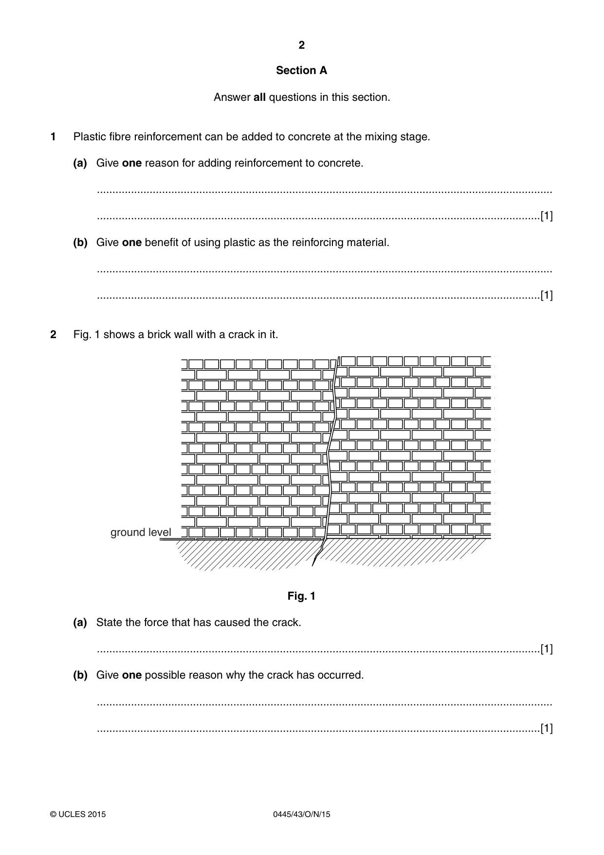
2 0445/43/O/N/15 © UCLES 2015 Section A Answer all questions in this section. 1 Plastic fibre reinforcement can be added to concrete at the mixing stage. (a) Give one reason for adding reinforcement to concrete. … …[1] (b) Give one benefit of using plastic as the reinforcing material. … …[1] 2 Fig. 1 shows a brick wall with a crack in it. ground level Fig. 1 (a) State the force that has caused the crack. …[1] (b) Give one possible reason why the crack has occurred. … …[1]
Question paper, page 3
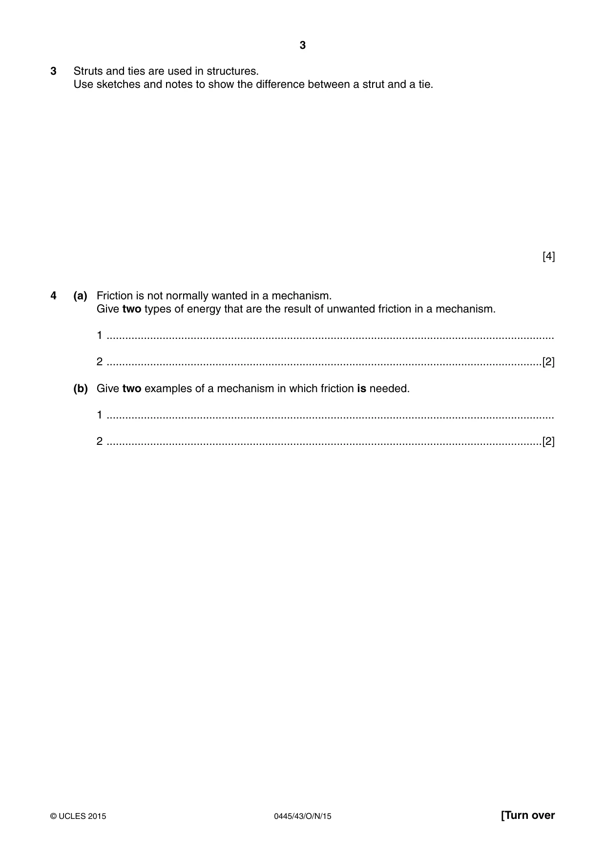
3 0445/43/O/N/15 © UCLES 2015 [Turn over 3 Struts and ties are used in structures. Use sketches and notes to show the difference between a strut and a tie. [4] 4 (a) Friction is not normally wanted in a mechanism. Give two types of energy that are the result of unwanted friction in a mechanism. 1 … 2 …[2] (b) Give two examples of a mechanism in which friction is needed. 1 … 2 …[2]
Question paper, page 4
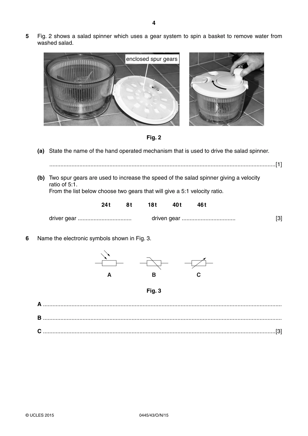
4 0445/43/O/N/15 © UCLES 2015 5 Fig. 2 shows a salad spinner which uses a gear system to spin a basket to remove water from washed salad. Fig. 2 (a) State the name of the hand operated mechanism that is used to drive the salad spinner. …[1] (b) Two spur gears are used to increase the speed of the salad spinner giving a velocity ratio of 5:1. From the list below choose two gears that will give a 5:1 velocity ratio. 24 t 8 t 18 t 40 t 46 t driver gear … driven gear … [3] 6 Name the electronic symbols shown in Fig. 3. A B C Fig. 3 A … B … C …[3]
Question paper, page 5
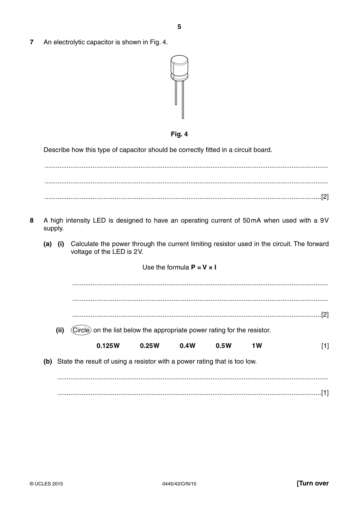
5 0445/43/O/N/15 © UCLES 2015 [Turn over 7 An electrolytic capacitor is shown in Fig. 4. Fig. 4 Describe how this type of capacitor should be correctly fitted in a circuit board. … … …[2] 8 A high intensity LED is designed to have an operating current of 50 mA when used with a 9 V supply. (a) (i) Calculate the power through the current limiting resistor used in the circuit. The forward voltage of the LED is 2 V. Use the formula P = V × I … … …[2] (ii) Circle on the list below the appropriate power rating for the resistor. 0.125 W 0.25 W 0.4 W 0.5 W 1 W [1] (b) State the result of using a resistor with a power rating that is too low. … …[1]
Question paper, page 6
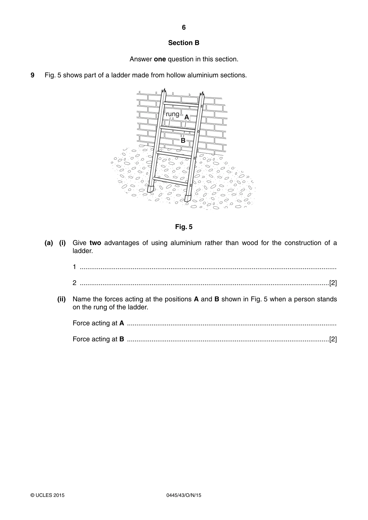
6 0445/43/O/N/15 © UCLES 2015 Section B Answer one question in this section. 9 Fig. 5 shows part of a ladder made from hollow aluminium sections. rung A B Fig. 5 (a) (i) Give two advantages of using aluminium rather than wood for the construction of a ladder. 1 … 2 …[2] (ii) Name the forces acting at the positions A and B shown in Fig. 5 when a person stands on the rung of the ladder. Force acting at A … Force acting at B …[2]
Question paper, page 7
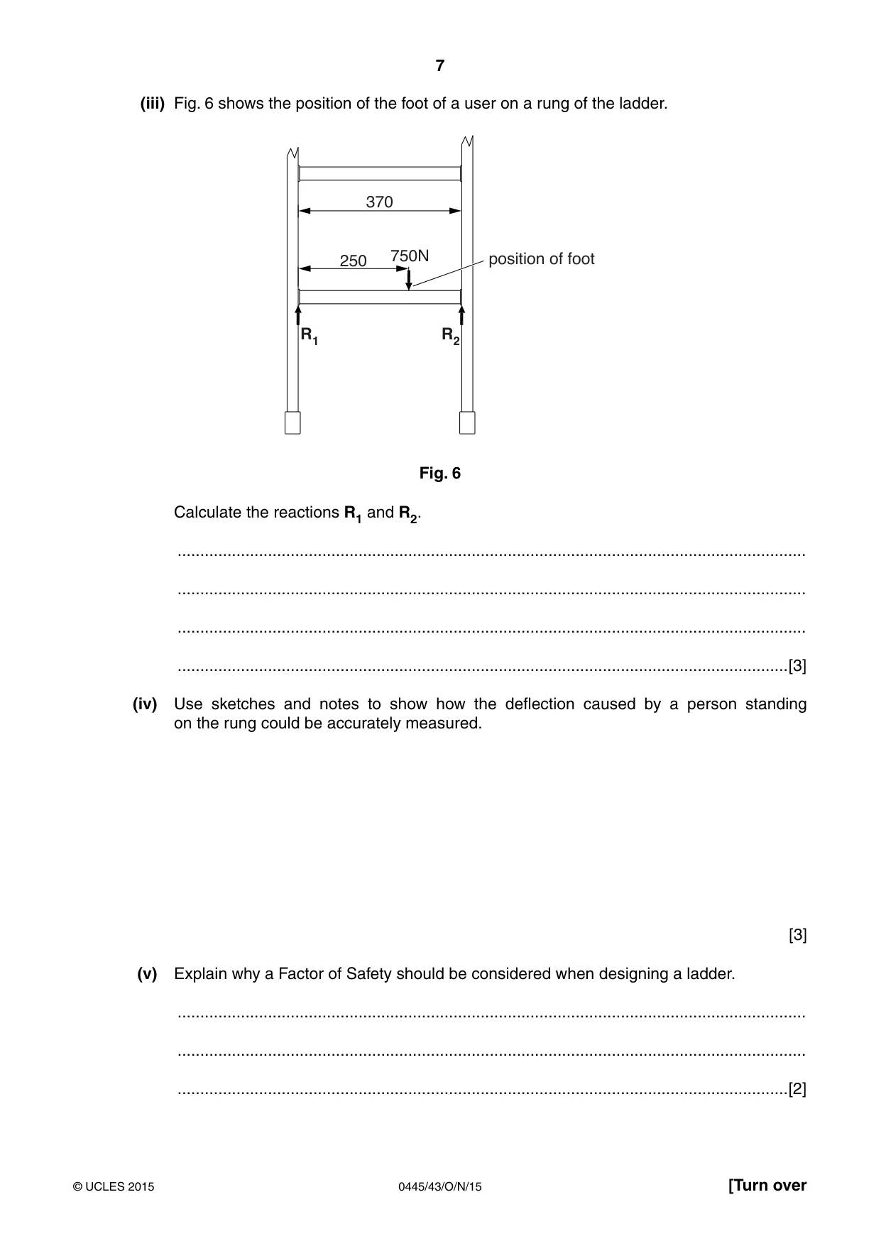
7 0445/43/O/N/15 © UCLES 2015 [Turn over (iii) Fig. 6 shows the position of the foot of a user on a rung of the ladder. 750N R1 R2 250 370 position of foot Fig. 6 Calculate the reactions R1 and R2. … … … …[3] (iv) Use sketches and notes to show how the deflection caused by a person standing on the rung could be accurately measured. [3] (v) Explain why a Factor of Safety should be considered when designing a ladder. … … …[2]
Question paper, page 8
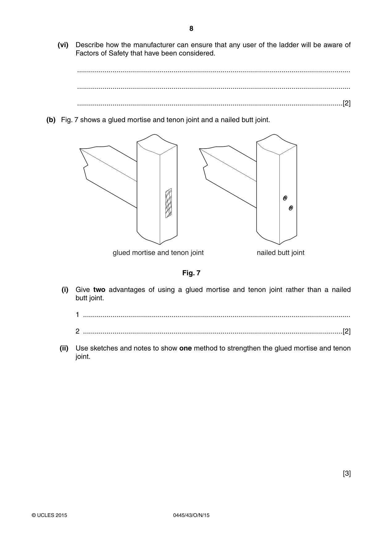
8 0445/43/O/N/15 © UCLES 2015 (vi) Describe how the manufacturer can ensure that any user of the ladder will be aware of Factors of Safety that have been considered. … … …[2] (b) Fig. 7 shows a glued mortise and tenon joint and a nailed butt joint. glued mortise and tenon joint nailed butt joint Fig. 7 (i) Give two advantages of using a glued mortise and tenon joint rather than a nailed butt joint. 1 … 2 …[2] (ii) Use sketches and notes to show one method to strengthen the glued mortise and tenon joint. [3]
Question paper, page 9
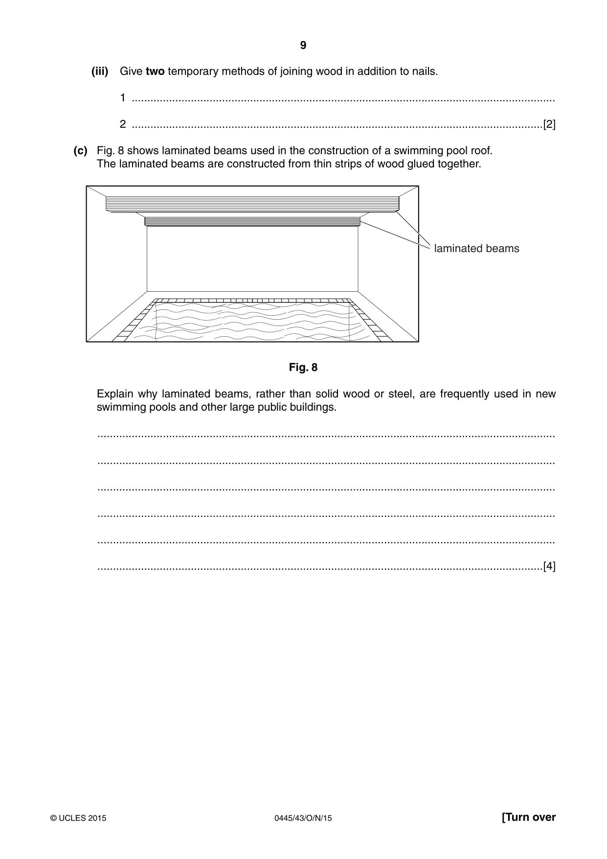
9 0445/43/O/N/15 © UCLES 2015 [Turn over (iii) Give two temporary methods of joining wood in addition to nails. 1 … 2 …[2] (c) Fig. 8 shows laminated beams used in the construction of a swimming pool roof. The laminated beams are constructed from thin strips of wood glued together. laminated beams Fig. 8 Explain why laminated beams, rather than solid wood or steel, are frequently used in new swimming pools and other large public buildings. … … … … … …[4]
Question paper, page 10
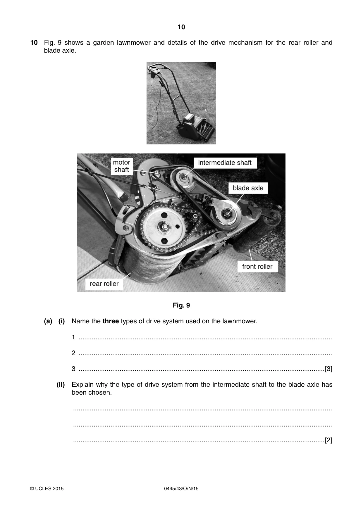
10 0445/43/O/N/15 © UCLES 2015 10 Fig. 9 shows a garden lawnmower and details of the drive mechanism for the rear roller and blade axle. Fig. 9 (a) (i) Name the three types of drive system used on the lawnmower. 1 … 2 … 3 …[3] (ii) Explain why the type of drive system from the intermediate shaft to the blade axle has been chosen. … … …[2]
Question paper, page 11
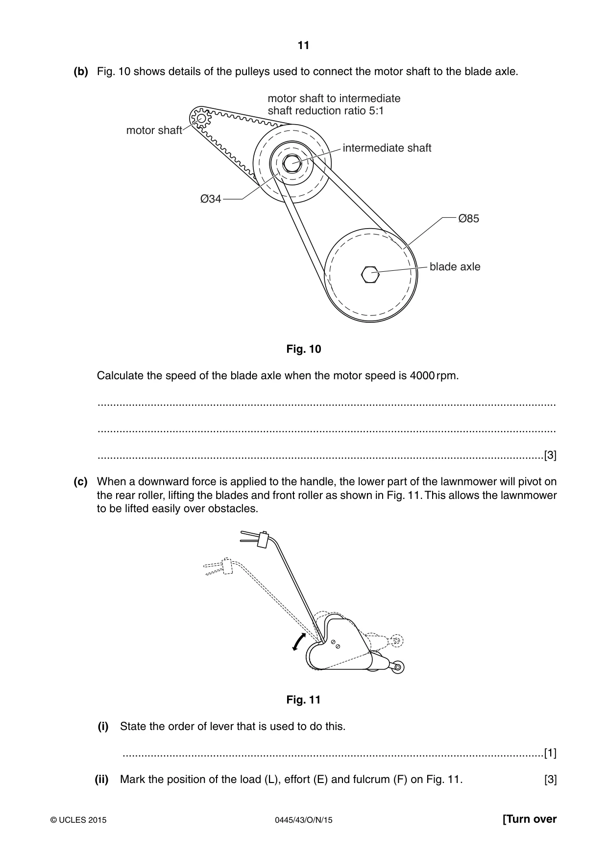
11 0445/43/O/N/15 © UCLES 2015 [Turn over (b) Fig. 10 shows details of the pulleys used to connect the motor shaft to the blade axle. blade axle motor shaft Ø34 Ø85 intermediate shaft motor shaft to intermediate shaft reduction ratio 5:1 Fig. 10 Calculate the speed of the blade axle when the motor speed is 4000 rpm. … … …[3] (c) When a downward force is applied to the handle, the lower part of the lawnmower will pivot on the rear roller, lifting the blades and front roller as shown in Fig. 11. This allows the lawnmower to be lifted easily over obstacles. Fig. 11 (i) State the order of lever that is used to do this. …[1] (ii) Mark the position of the load (L), effort (E) and fulcrum (F) on Fig. 11. [3]
Question paper, page 12
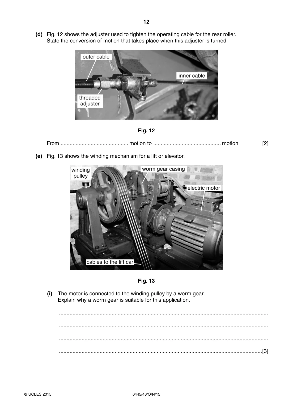
12 0445/43/O/N/15 © UCLES 2015 (d) Fig. 12 shows the adjuster used to tighten the operating cable for the rear roller. State the conversion of motion that takes place when this adjuster is turned. Fig. 12 From … motion to … motion [2] (e) Fig. 13 shows the winding mechanism for a lift or elevator. Fig. 13 (i) The motor is connected to the winding pulley by a worm gear. Explain why a worm gear is suitable for this application. … … … …[3]
Question paper, page 13
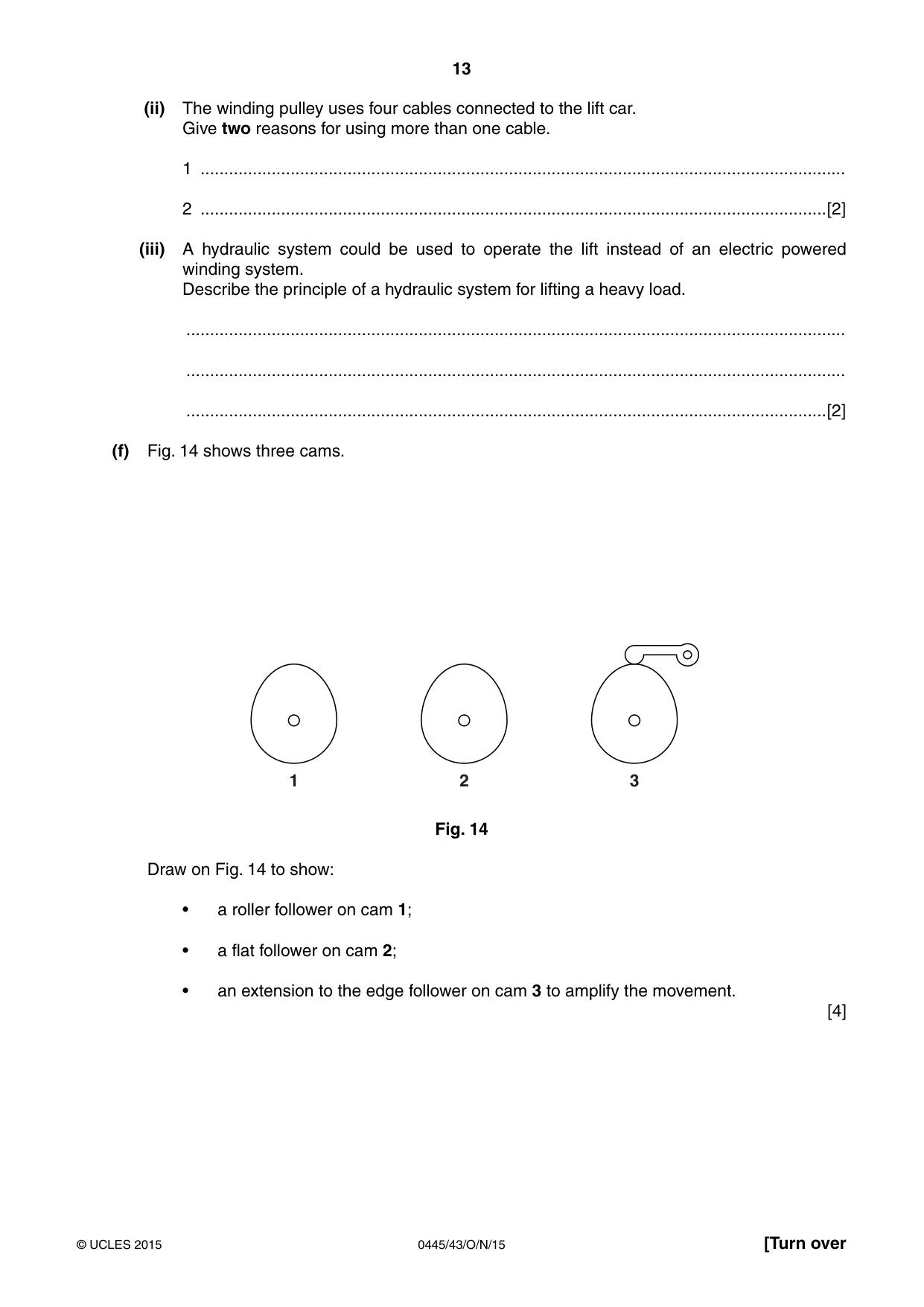
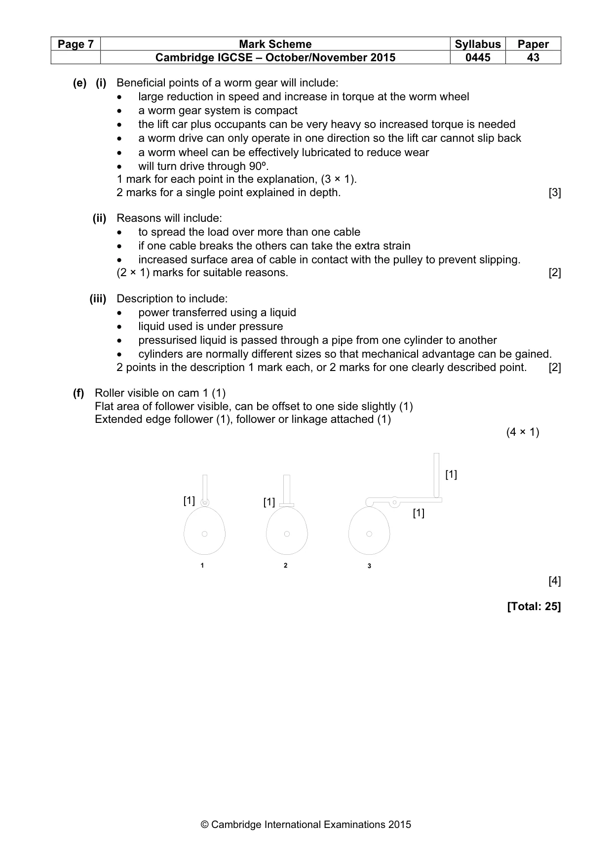
13 0445/43/O/N/15 © UCLES 2015 [Turn over (ii) The winding pulley uses four cables connected to the lift car. Give two reasons for using more than one cable. 1 … 2 …[2] (iii) A hydraulic system could be used to operate the lift instead of an electric powered winding system. Describe the principle of a hydraulic system for lifting a heavy load. … … …[2] (f) Fig. 14 shows three cams. 1 2 3 Fig. 14 Draw on Fig. 14 to show: • a roller follower on cam 1; • a flat follower on cam 2; • an extension to the edge follower on cam 3 to amplify the movement. [4]
Question paper, page 14
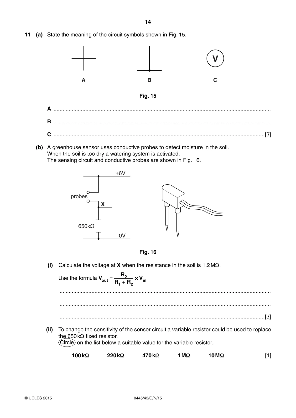
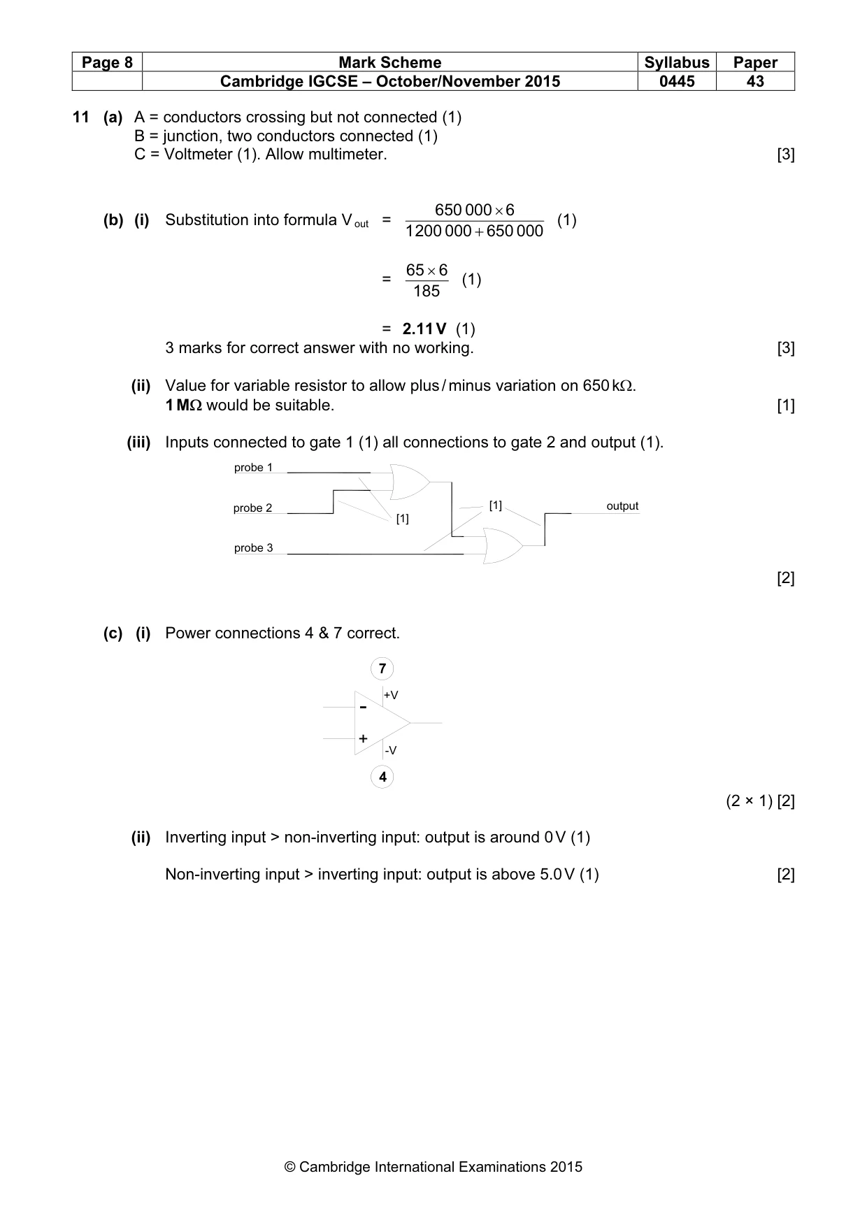
14 0445/43/O/N/15 © UCLES 2015 11 (a) State the meaning of the circuit symbols shown in Fig. 15. V C B A Fig. 15 A … B … C …[3] (b) A greenhouse sensor uses conductive probes to detect moisture in the soil. When the soil is too dry a watering system is activated. The sensing circuit and conductive probes are shown in Fig. 16. +6V 0V 650k probes X Fig. 16 (i) Calculate the voltage at X when the resistance in the soil is 1.2 MΩ. Use the formula Vout = R2 R1 + R2 × Vin … … …[3] (ii) To change the sensitivity of the sensor circuit a variable resistor could be used to replace the 650 kΩ fixed resistor. Circle on the list below a suitable value for the variable resistor. 100 kΩ 220 kΩ 470 kΩ 1 MΩ 10 MΩ [1]
Question paper, page 15
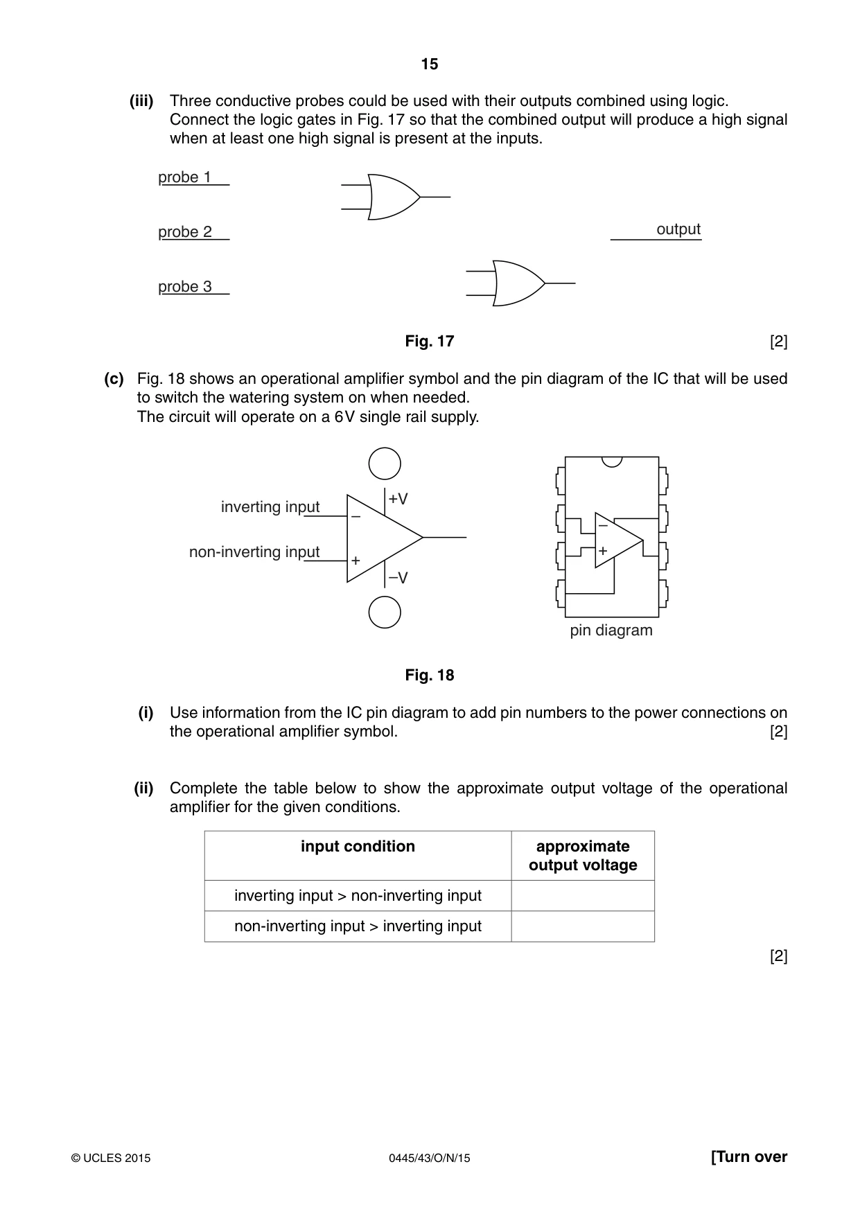
15 0445/43/O/N/15 © UCLES 2015 [Turn over (iii) Three conductive probes could be used with their outputs combined using logic. Connect the logic gates in Fig. 17 so that the combined output will produce a high signal when at least one high signal is present at the inputs. probe 1 probe 2 probe 3 output Fig. 17 [2] (c) Fig. 18 shows an operational amplifier symbol and the pin diagram of the IC that will be used to switch the watering system on when needed. The circuit will operate on a 6 V single rail supply. inverting input + +V –V – + pin diagram – non-inverting input Fig. 18 (i) Use information from the IC pin diagram to add pin numbers to the power connections on the operational amplifier symbol. [2] (ii) Complete the table below to show the approximate output voltage of the operational amplifier for the given conditions. input condition approximate output voltage inverting input > non-inverting input non-inverting input > inverting input [2]
Question paper, page 16
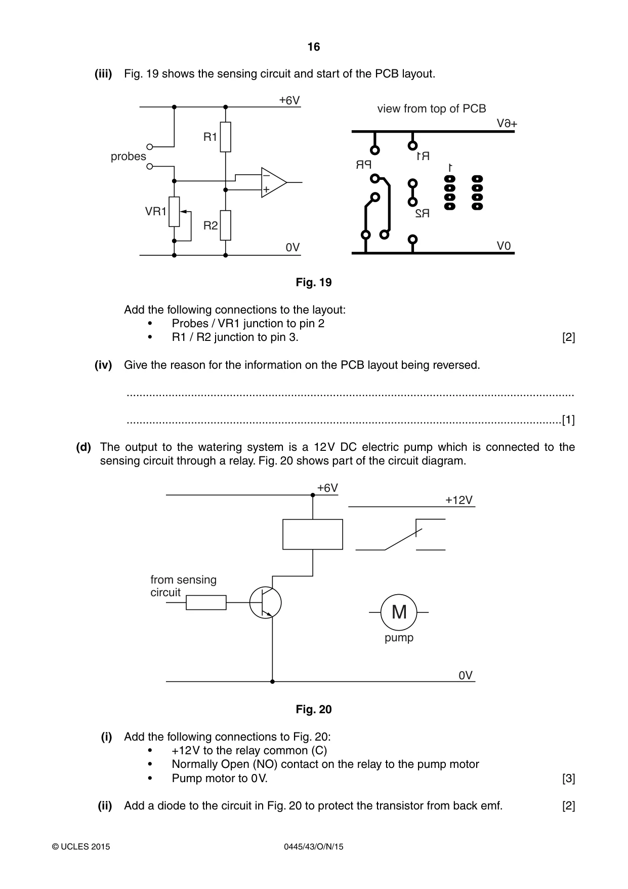
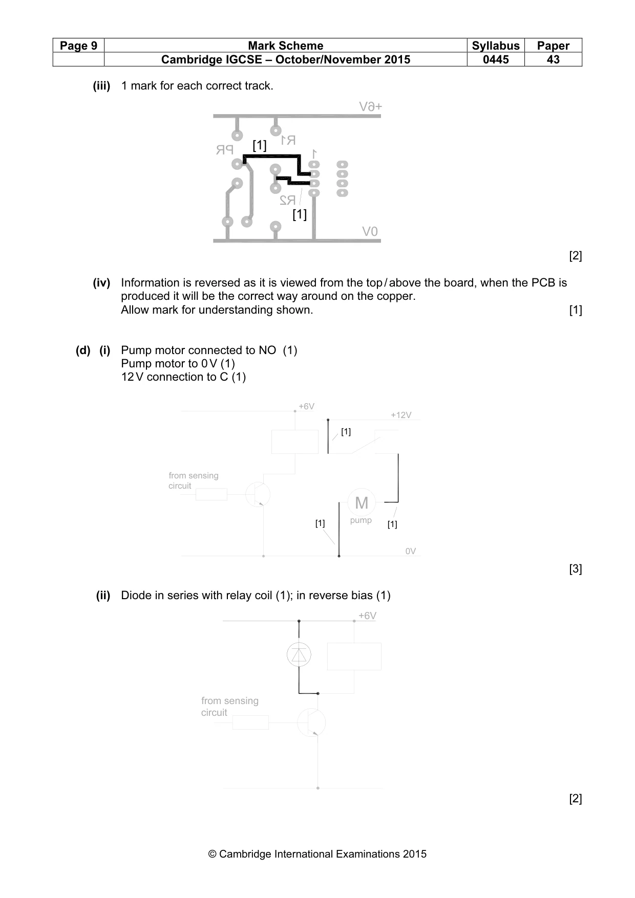
16 0445/43/O/N/15 © UCLES 2015 (iii) Fig. 19 shows the sensing circuit and start of the PCB layout. +6V 0V R2 + – VR1 R1 view from top of PCB R1 1 R2 0V +6V PR probes Fig. 19 Add the following connections to the layout: • Probes / VR1 junction to pin 2 • R1 / R2 junction to pin 3. [2] (iv) Give the reason for the information on the PCB layout being reversed. … …[1] (d) The output to the watering system is a 12 V DC electric pump which is connected to the sensing circuit through a relay. Fig. 20 shows part of the circuit diagram. from sensing circuit pump 0V +12V +6V M Fig. 20 (i) Add the following connections to Fig. 20: • +12 V to the relay common (C) • Normally Open (NO) contact on the relay to the pump motor • Pump motor to 0 V. [3] (ii) Add a diode to the circuit in Fig. 20 to protect the transistor from back emf. [2]
Question paper, page 17
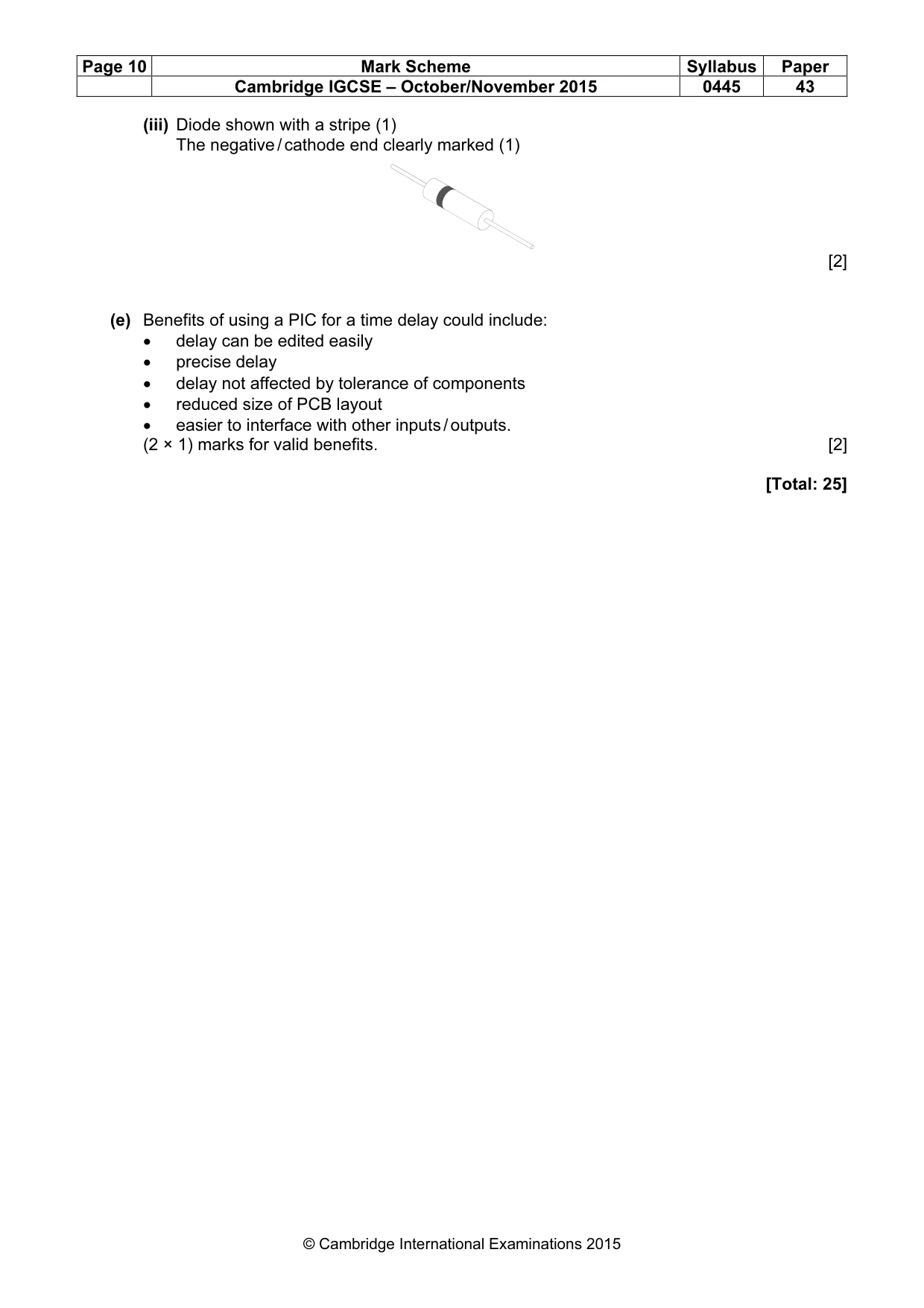
17 0445/43/O/N/15 © UCLES 2015 (iii) Use sketches and notes to show how the cathode (negative end) of the diode would be identified on the component. [2] (e) To allow water to pass into the soil the pump must be switched on for a minimum period of time. The time delay between the electric pump switching on and switching off could be controlled either by a 555 timer IC or by a programmable IC. Give two benefits of using a programmable IC to provide a time delay. 1 … … 2 … …[2]
Question paper, page 18
18 0445/43/O/N/15 © UCLES 2015 BLANK PAGE
Question paper, page 19
19 0445/43/O/N/15 © UCLES 2015 BLANK PAGE
Question paper, page 20
20 0445/43/O/N/15 © UCLES 2015 Permission to reproduce items where third-party owned material protected by copyright is included has been sought and cleared where possible. Every reasonable effort has been made by the publisher (UCLES) to trace copyright holders, but if any items requiring clearance have unwittingly been included, the publisher will be pleased to make amends at the earliest possible opportunity. To avoid the issue of disclosure of answer-related information to candidates, all copyright acknowledgements are reproduced online in the Cambridge International Examinations Copyright Acknowledgements Booklet. This is produced for each series of examinations and is freely available to download at www.cie.org.uk after the live examination series. Cambridge International Examinations is part of the Cambridge Assessment Group. Cambridge Assessment is the brand name of University of Cambridge Local Examinations Syndicate (UCLES), which is itself a department of the University of Cambridge. BLANK PAGE
Mark scheme, page 1
® IGCSE is the registered trademark of Cambridge International Examinations. CAMBRIDGE INTERNATIONAL EXAMINATIONS Cambridge International General Certificate of Secondary Education MARK SCHEME for the October/November 2015 series 0445 DESIGN AND TECHNOLOGY 0445/43 Paper 4 (Systems and Control), maximum raw mark 50 This mark scheme is published as an aid to teachers and candidates, to indicate the requirements of the examination. It shows the basis on which Examiners were instructed to award marks. It does not indicate the details of the discussions that took place at an Examiners’ meeting before marking began, which would have considered the acceptability of alternative answers. Mark schemes should be read in conjunction with the question paper and the Principal Examiner Report for Teachers. Cambridge will not enter into discussions about these mark schemes. Cambridge is publishing the mark schemes for the October/November 2015 series for most Cambridge IGCSE®, Cambridge International A and AS Level components and some Cambridge O Level components.
Mark scheme, page 2
Page 2 Mark Scheme Syllabus Paper Cambridge IGCSE – October/November 2015 0445 43 © Cambridge International Examinations 2015 Section A 1 (a) Reinforcement is added to improve the tensile strength of the material and the resistance to bending. Allow other valid benefits. [1] (b) Plastic based reinforcement will not corrode on exposure to air, unlike steel. The reinforcement can be added during the mixing of the concrete so saves time. [1] 2 (a) The crack is caused by shear force (1). Allow reference to the weight of the wall or to gravity. [1] (b) Reason could be movement in the ground / foundation not strong enough, earthquake damage.1 mark for suitable reason. [1] 3 A strut will resist compression (1) and a tie will resist tension (1). Suitable example / drawing used, 1 mark for each. (2 × 1) Allow force arrows on diagrams to illustrate the forces resisted. [4] 4 (a) Heat and sound will result from unwanted friction in a mechanism. (2 × 1) [2] (b) Examples include: Tripod / shear legs on the ground, vee belt and pulley, screw threads. Allow braking devices on vehicles / machines, ratchet and pawl. (2 × 1) marks for valid examples. [2] 5 (a) The mechanism is a crank. [1] (b) Driver gear is 40 teeth. Driven gear is 8 teeth. 1 mark each for correct gears, 1 mark for driver / driven correctly matched to gears. (3 × 1) [3] 6 Symbol A – LDR / Light Dependent Resistor (1) Symbol B – Thermistor (1) Symbol C – Variable resistor (1). Accept potentiometer or rheostat. [3] 7 The negative / cathode leg must be identified (1). The negative leg is normally shorter or has a marking on the casing (1). The capacitor is inserted into the PCB with negative leg matching negative symbol on the board (1). (2 × 1) marks. Allow marks for understanding shown. [2]
Mark scheme, page 3
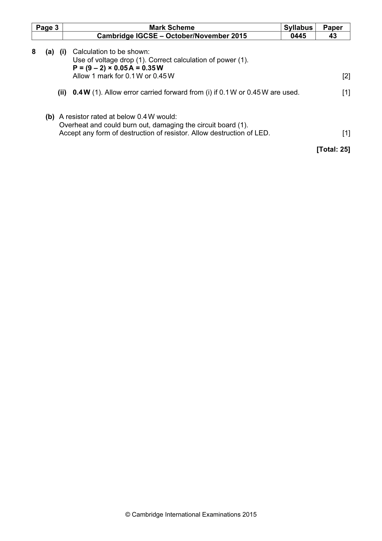
Page 3 Mark Scheme Syllabus Paper Cambridge IGCSE – October/November 2015 0445 43 © Cambridge International Examinations 2015 8 (a) (i) Calculation to be shown: Use of voltage drop (1). Correct calculation of power (1). P = (9 – 2) × 0.05 A = 0.35 W Allow 1 mark for 0.1 W or 0.45 W [2] (ii) 0.4 W (1). Allow error carried forward from (i) if 0.1 W or 0.45 W are used. [1] (b) A resistor rated at below 0.4 W would: Overheat and could burn out, damaging the circuit board (1). Accept any form of destruction of resistor. Allow destruction of LED. [1] [Total: 25]
Mark scheme, page 4
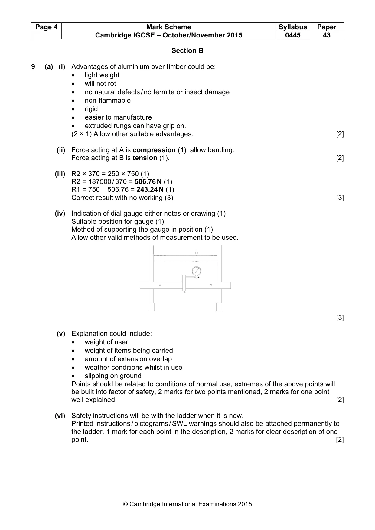
Page 4 Mark Scheme Syllabus Paper Cambridge IGCSE – October/November 2015 0445 43 © Cambridge International Examinations 2015 Section B 9 (a) (i) Advantages of aluminium over timber could be: • light weight • will not rot • no natural defects / no termite or insect damage • non-flammable • rigid • easier to manufacture • extruded rungs can have grip on. (2 × 1) Allow other suitable advantages. [2] (ii) Force acting at A is compression (1), allow bending. Force acting at B is tension (1). [2] (iii) R2 × 370 = 250 × 750 (1) R2 = 187500 / 370 = 506.76 N (1) R1 = 750 – 506.76 = 243.24 N (1) Correct result with no working (3). [3] (iv) Indication of dial gauge either notes or drawing (1) Suitable position for gauge (1) Method of supporting the gauge in position (1) Allow other valid methods of measurement to be used. [3] (v) Explanation could include: • weight of user • weight of items being carried • amount of extension overlap • weather conditions whilst in use • slipping on ground Points should be related to conditions of normal use, extremes of the above points will be built into factor of safety, 2 marks for two points mentioned, 2 marks for one point well explained. [2] (vi) Safety instructions will be with the ladder when it is new. Printed instructions / pictograms / SWL warnings should also be attached permanently to the ladder. 1 mark for each point in the description, 2 marks for clear description of one point. [2]
Mark scheme, page 5
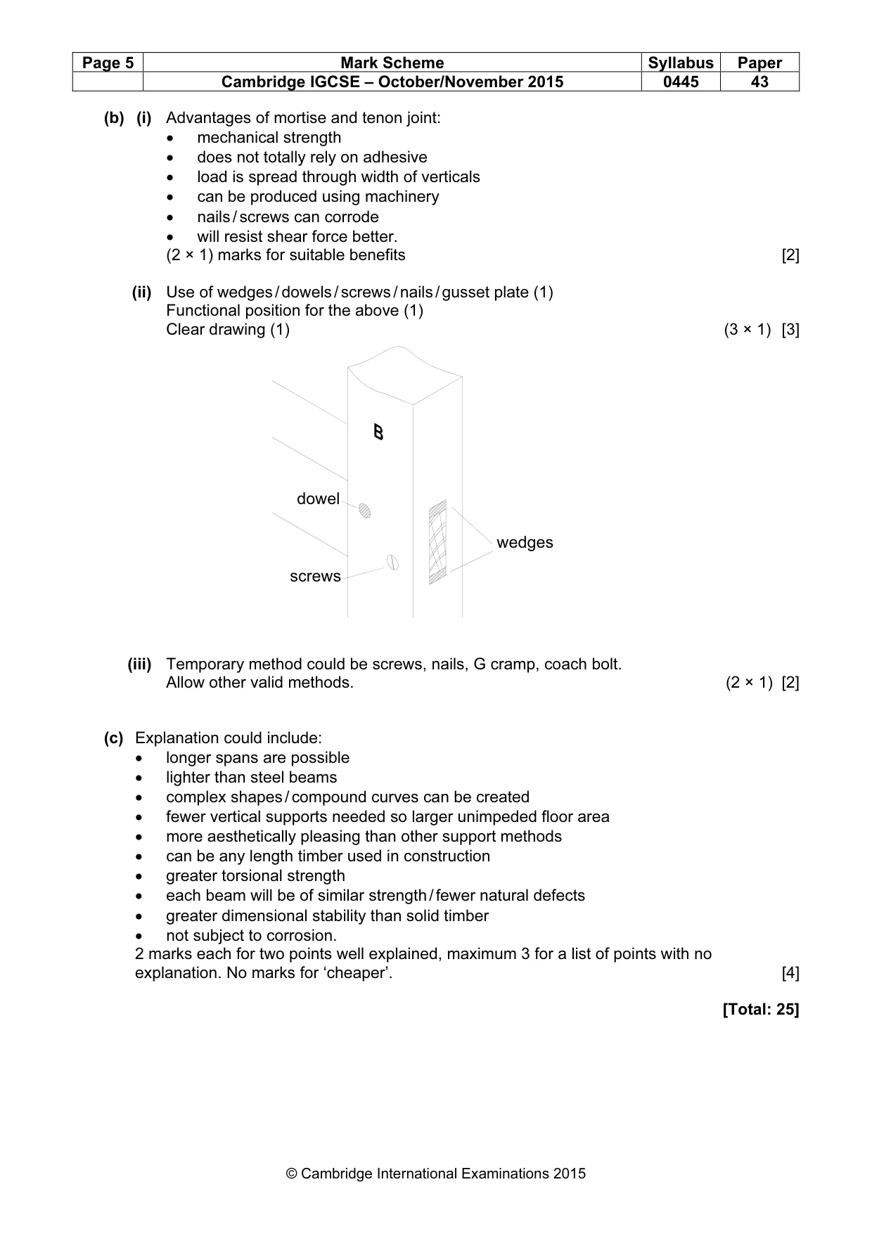
Page 5 Mark Scheme Syllabus Paper Cambridge IGCSE – October/November 2015 0445 43 © Cambridge International Examinations 2015 (b) (i) Advantages of mortise and tenon joint: • mechanical strength • does not totally rely on adhesive • load is spread through width of verticals • can be produced using machinery • nails / screws can corrode • will resist shear force better. (2 × 1) marks for suitable benefits [2] (ii) Use of wedges / dowels / screws / nails / gusset plate (1) Functional position for the above (1) Clear drawing (1) (3 × 1) [3] (iii) Temporary method could be screws, nails, G cramp, coach bolt. Allow other valid methods. (2 × 1) [2] (c) Explanation could include: • longer spans are possible • lighter than steel beams • complex shapes / compound curves can be created • fewer vertical supports needed so larger unimpeded floor area • more aesthetically pleasing than other support methods • can be any length timber used in construction • greater torsional strength • each beam will be of similar strength / fewer natural defects • greater dimensional stability than solid timber • not subject to corrosion. 2 marks each for two points well explained, maximum 3 for a list of points with no explanation. No marks for ‘cheaper’. [4] [Total: 25] wedges dowel screws
Mark scheme, page 6
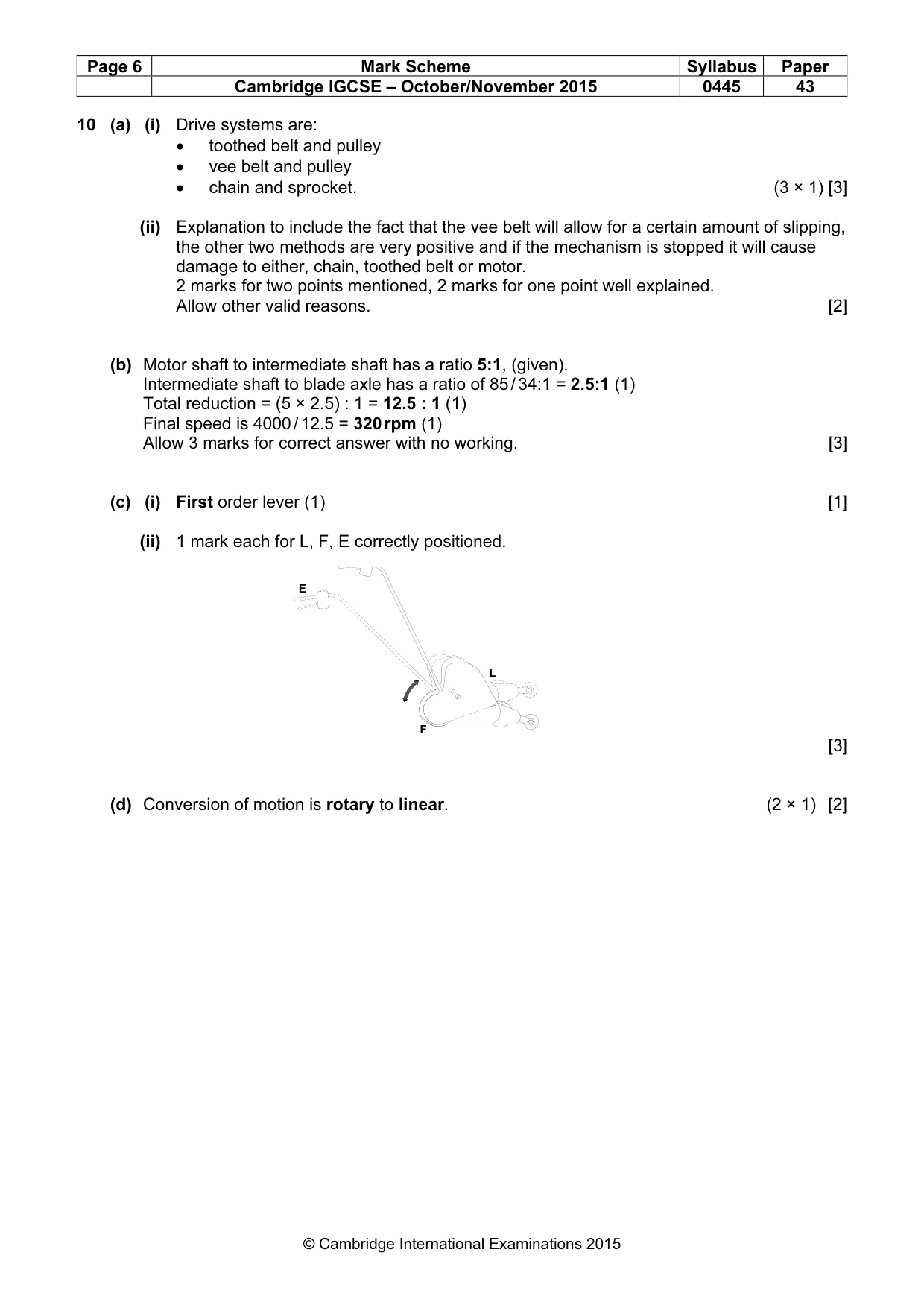
Page 6 Mark Scheme Syllabus Paper Cambridge IGCSE – October/November 2015 0445 43 © Cambridge International Examinations 2015 10 (a) (i) Drive systems are: • toothed belt and pulley • vee belt and pulley • chain and sprocket. (3 × 1) [3] (ii) Explanation to include the fact that the vee belt will allow for a certain amount of slipping, the other two methods are very positive and if the mechanism is stopped it will cause damage to either, chain, toothed belt or motor. 2 marks for two points mentioned, 2 marks for one point well explained. Allow other valid reasons. [2] (b) Motor shaft to intermediate shaft has a ratio 5:1, (given). Intermediate shaft to blade axle has a ratio of 85 / 34:1 = 2.5:1 (1) Total reduction = (5 × 2.5) : 1 = 12.5 : 1 (1) Final speed is 4000 / 12.5 = 320 rpm (1) Allow 3 marks for correct answer with no working. [3] (c) (i) First order lever (1) [1] (ii) 1 mark each for L, F, E correctly positioned. [3] (d) Conversion of motion is rotary to linear. (2 × 1) [2] L F E
Mark scheme, page 7
Page 7 Mark Scheme Syllabus Paper Cambridge IGCSE – October/November 2015 0445 43 © Cambridge International Examinations 2015 (e) (i) Beneficial points of a worm gear will include: • large reduction in speed and increase in torque at the worm wheel • a worm gear system is compact • the lift car plus occupants can be very heavy so increased torque is needed • a worm drive can only operate in one direction so the lift car cannot slip back • a worm wheel can be effectively lubricated to reduce wear • will turn drive through 90º. 1 mark for each point in the explanation, (3 × 1). 2 marks for a single point explained in depth. [3] (ii) Reasons will include: • to spread the load over more than one cable • if one cable breaks the others can take the extra strain • increased surface area of cable in contact with the pulley to prevent slipping. (2 × 1) marks for suitable reasons. [2] (iii) Description to include: • power transferred using a liquid • liquid used is under pressure • pressurised liquid is passed through a pipe from one cylinder to another • cylinders are normally different sizes so that mechanical advantage can be gained. 2 points in the description 1 mark each, or 2 marks for one clearly described point. [2] (f) Roller visible on cam 1 (1) Flat area of follower visible, can be offset to one side slightly (1) Extended edge follower (1), follower or linkage attached (1) (4 × 1) [4] [Total: 25] 2 1 3 [1] [1] [1] [1]
Mark scheme, page 8
Page 8 Mark Scheme Syllabus Paper Cambridge IGCSE – October/November 2015 0445 43 © Cambridge International Examinations 2015 11 (a) A = conductors crossing but not connected (1) B = junction, two conductors connected (1) C = Voltmeter (1). Allow multimeter. [3] (b) (i) Substitution into formula V out = 650 000 6 1 200 000 650 000 × + (1) = 65 6 185 × (1) = 2.11 V (1) 3 marks for correct answer with no working. [3] (ii) Value for variable resistor to allow plus / minus variation on 650 kΩ. 1 MΩ would be suitable. [1] (iii) Inputs connected to gate 1 (1) all connections to gate 2 and output (1). [2] (c) (i) Power connections 4 & 7 correct. (2 × 1) [2] (ii) Inverting input > non-inverting input: output is around 0 V (1) Non-inverting input > inverting input: output is above 5.0 V (1) [2] probe 1 probe 2 probe 3 output [1] [1] - + +V -V 7 4
Mark scheme, page 9
Page 9 Mark Scheme Syllabus Paper Cambridge IGCSE – October/November 2015 0445 43 © Cambridge International Examinations 2015 (iii) 1 mark for each correct track. [2] (iv) Information is reversed as it is viewed from the top / above the board, when the PCB is produced it will be the correct way around on the copper. Allow mark for understanding shown. [1] (d) (i) Pump motor connected to NO (1) Pump motor to 0 V (1) 12 V connection to C (1) [3] (ii) Diode in series with relay coil (1); in reverse bias (1) [2] [1] [1] +6V from sensing circuit +6V +12V 0V from sensing circuit M pump [1] [1] [1]
Mark scheme, page 10
Page 10 Mark Scheme Syllabus Paper Cambridge IGCSE – October/November 2015 0445 43 © Cambridge International Examinations 2015 (iii) Diode shown with a stripe (1) The negative / cathode end clearly marked (1) [2] (e) Benefits of using a PIC for a time delay could include: • delay can be edited easily • precise delay • delay not affected by tolerance of components • reduced size of PCB layout • easier to interface with other inputs / outputs. (2 × 1) marks for valid benefits. [2] [Total: 25]
What you needed in this session
Cambridge’s own grade thresholds for 2015 Oct/Nov, Paper 4 · Variant 3. A higher threshold means an easier paper — the bar moves with how the cohort did.