Cambridge IGCSE Design and Technology 0445 — 2015 May/June Paper 4 · Variant 2
0445/42/M/J/15 · 50 marks · ≈56 min
The question paper and its mark scheme, free to read here and free to download. This is Cambridge’s own paper, exactly as it was sat.
Question paper20 pages


Mark scheme9 pages
Answers below. Sit the paper first if you are practising.
Paper as text
Question paper, page 1
This document consists of 17 printed pages and 3 blank pages. DC (ST/SW) 107471 © UCLES 2015 [Turn over Cambridge International Examinations Cambridge International General Certificate of Secondary Education * 5 0 0 3 6 7 6 5 6 4 * DESIGN AND TECHNOLOGY 0445/42 Paper 4 Systems and Control May/June 2015 1 hour Candidates answer on the Question Paper. No Additional Materials are required. READ THESE INSTRUCTIONS FIRST Write your Centre number, candidate number and name on all the work you hand in. Write in dark blue or black pen. You may use an HB pencil for any diagrams or graphs. Do not use staples, paper clips, glue or correction fluid. DO NOT WRITE IN ANY BARCODES. You may use a calculator. Section A Answer all questions in this section. Section B Answer one question in this section. At the end of the examination, fasten all your work securely together. The number of marks is given in brackets [ ] at the end of each question or part question. The total of the marks for this paper is 50.
Question paper, page 2
2 0445/42/M/J/15 © UCLES 2015 Section A Answer all questions in this section. 1 (a) Fig. 1 shows two sensing components with their circuit symbols. Name each component. -t° A B Fig. 1 A … [1] B … [1] (b) Fig. 2 shows a resistance graph for sensor A. resistance (k1) time (seconds) 0 10 0 20 30 40 50 1 2 3 4 5 Fig. 2 Describe what has caused the change in resistance shown in the graph. … … … [2]
Question paper, page 3
3 0445/42/M/J/15 © UCLES 2015 [Turn over 2 (a) Resistors can be connected in series to provide a precise value. Circle the values from the list below that will give a resistance of 1.4 MΩ. 1 kΩ Ω 680 kΩ 390 Ω Ω 470 Ω Ω 330 kΩ Ω 680 Ω Ω 390 kΩ [3] (b) In the space below draw two resistor symbols connected in series. [1] 3 Plastics and plywood can both be used to make a casing for an electronic project. Give one reason why plastics may be chosen rather than wood. … … [1] 4 Fig. 3 shows a can opener in the open position and in the closed position. The two hand grips, A and B pivot about point C to bring the cutting wheel into contact with the can. A cutting wheel C B open position closed position Fig. 3 (a) State the order of lever used when the hand grips are closed to make the cutting wheel pierce a can. … [1] (b) Describe the type of motion that occurs when the hand grips are closed. … [1] (c) Draw force arrows on Fig. 3 to show where effort should be placed on grips A and B to apply the maximum load at the cutting wheel. [2]
Question paper, page 4
4 0445/42/M/J/15 © UCLES 2015 5 Fig. 4 shows a close-up view of the can opener mechanism. Describe two effects of using gear wheels with the same number of teeth. handle X 13t gear 13t gear cutting wheel Fig. 4 1 … 2 … [2] 6 Stored energy is often used for powering mechanisms. Give two examples of stored energy used in mechanisms. 1 … 2 … [2] 7 Fig. 5 shows a reinforced concrete beam. Use notes and sketches to explain why the reinforcing rods are positioned as shown. reinforcing rods / wires below centre Fig. 5 [3]
Question paper, page 5
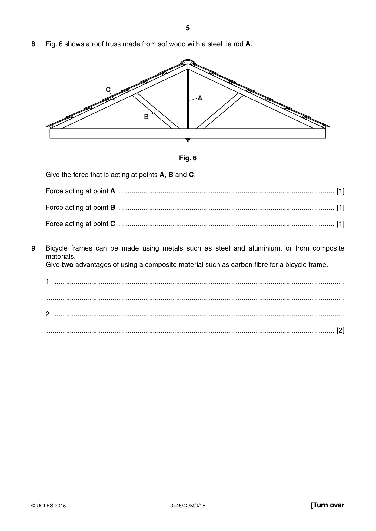
5 0445/42/M/J/15 © UCLES 2015 [Turn over 8 Fig. 6 shows a roof truss made from softwood with a steel tie rod A. A B C Fig. 6 Give the force that is acting at points A, B and C. Force acting at point A … [1] Force acting at point B … [1] Force acting at point C … [1] 9 Bicycle frames can be made using metals such as steel and aluminium, or from composite materials. Give two advantages of using a composite material such as carbon fibre for a bicycle frame. 1 … … 2 … … [2]
Question paper, page 6
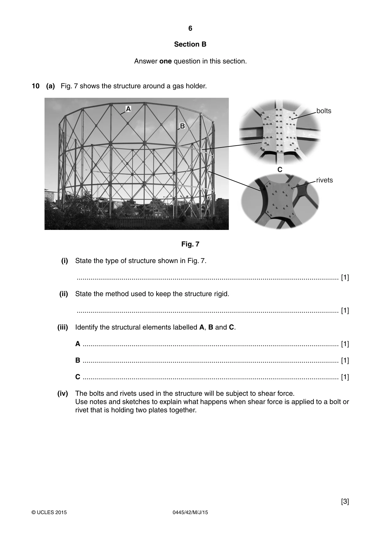
6 0445/42/M/J/15 © UCLES 2015 Section B Answer one question in this section. 10 (a) Fig. 7 shows the structure around a gas holder. C bolts rivets B A Fig. 7 (i) State the type of structure shown in Fig. 7. … [1] (ii) State the method used to keep the structure rigid. … [1] (iii) Identify the structural elements labelled A, B and C. A … [1] B … [1] C … [1] (iv) The bolts and rivets used in the structure will be subject to shear force. Use notes and sketches to explain what happens when shear force is applied to a bolt or rivet that is holding two plates together. [3]
Question paper, page 7
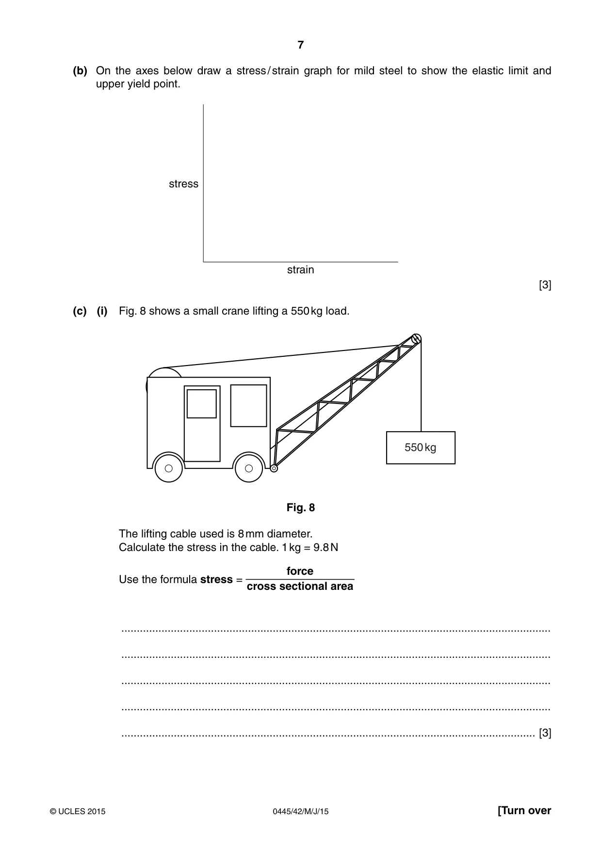
7 0445/42/M/J/15 © UCLES 2015 [Turn over (b) On the axes below draw a stress / strain graph for mild steel to show the elastic limit and upper yield point. stress strain [3] (c) (i) Fig. 8 shows a small crane lifting a 550 kg load. 550 kg Fig. 8 The lifting cable used is 8 mm diameter. Calculate the stress in the cable. 1 kg = 9.8 N Use the formula stress = force cross sectional area … … … … … [3]
Question paper, page 8
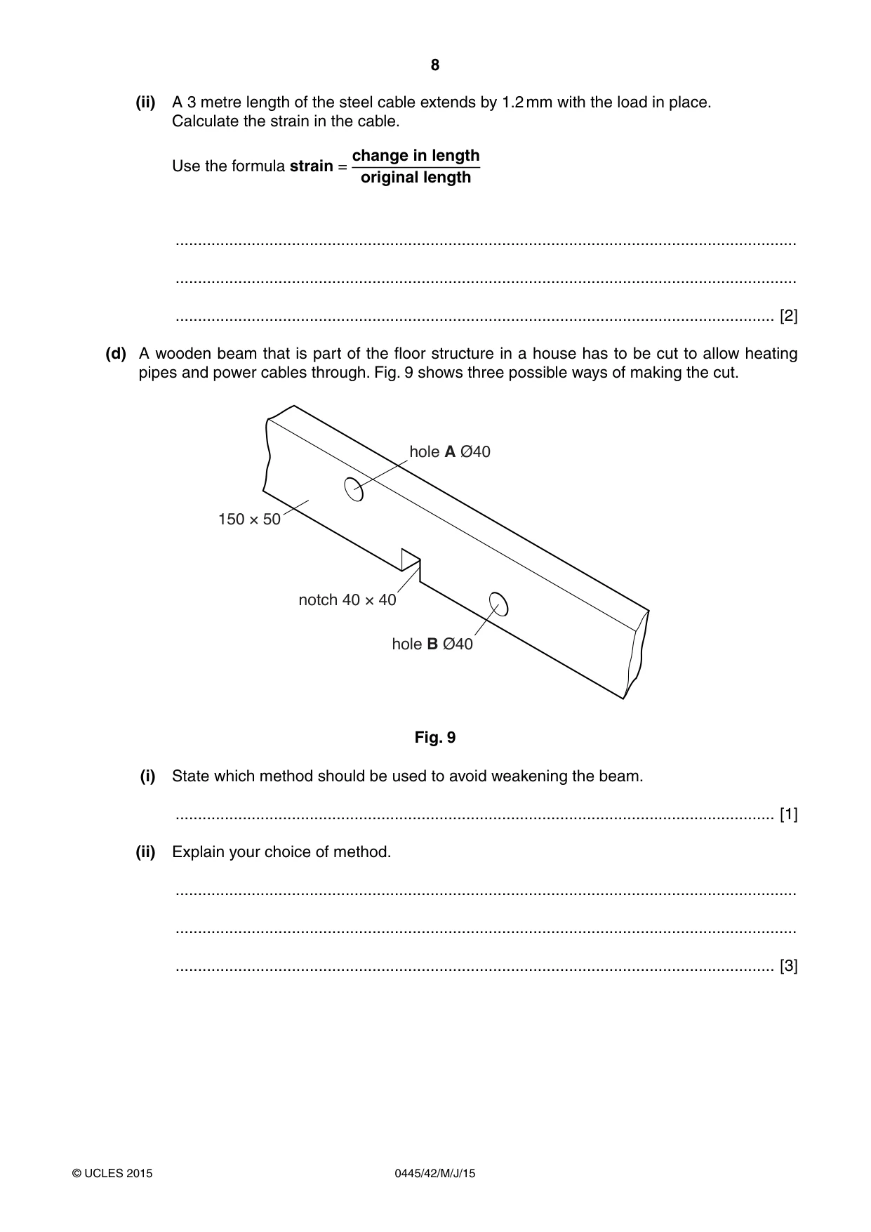
8 0445/42/M/J/15 © UCLES 2015 (ii) A 3 metre length of the steel cable extends by 1.2 mm with the load in place. Calculate the strain in the cable. Use the formula strain = change in length original length … … … [2] (d) A wooden beam that is part of the floor structure in a house has to be cut to allow heating pipes and power cables through. Fig. 9 shows three possible ways of making the cut. 150 × 50 notch 40 × 40 hole A Ø40 hole B Ø40 Fig. 9 (i) State which method should be used to avoid weakening the beam. … [1] (ii) Explain your choice of method. … … … [3]
Question paper, page 9
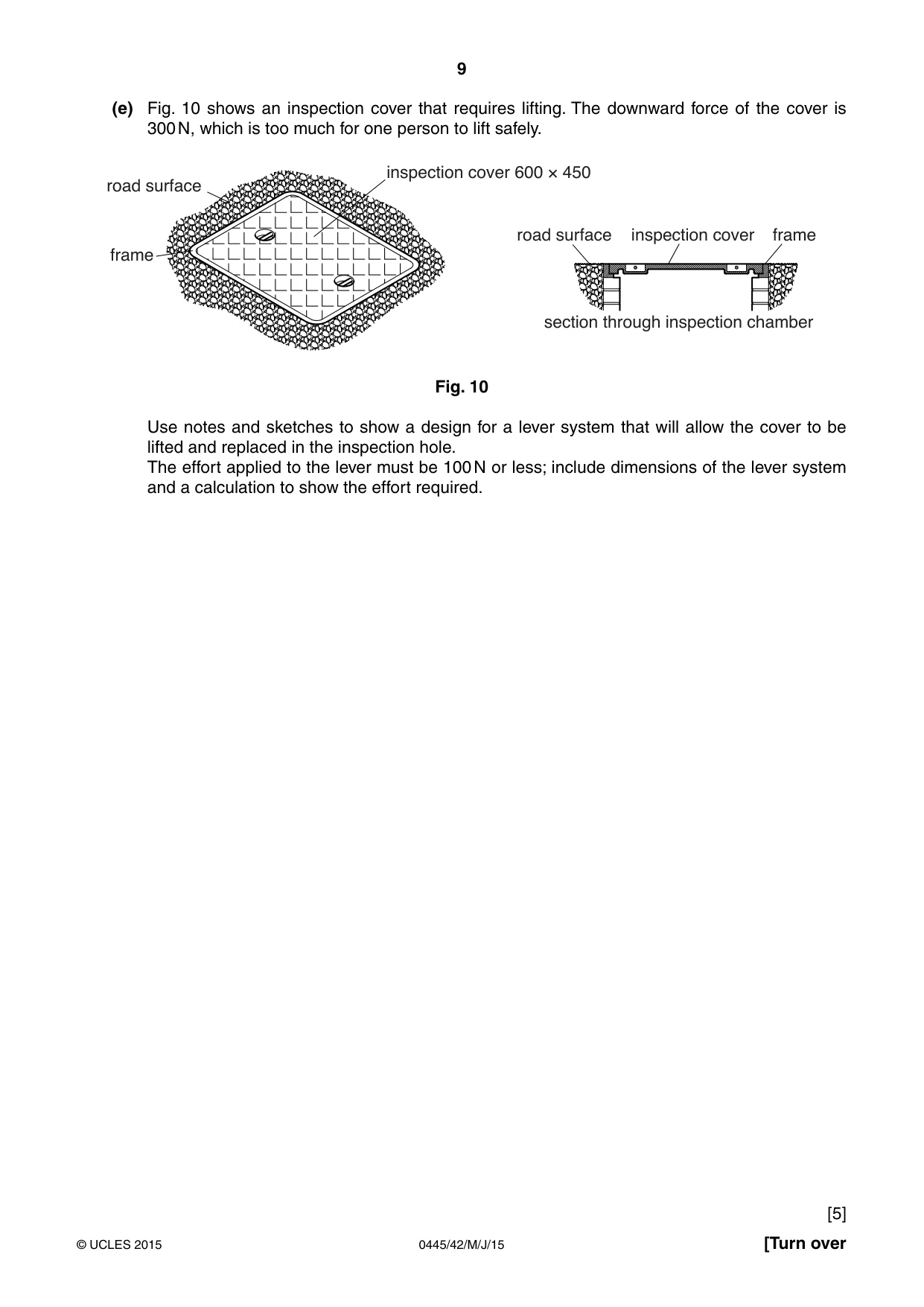
9 0445/42/M/J/15 © UCLES 2015 [Turn over (e) Fig. 10 shows an inspection cover that requires lifting. The downward force of the cover is 300 N, which is too much for one person to lift safely. inspection cover 600 × 450 road surface inspection cover road surface section through inspection chamber frame frame Fig. 10 Use notes and sketches to show a design for a lever system that will allow the cover to be lifted and replaced in the inspection hole. The effort applied to the lever must be 100 N or less; include dimensions of the lever system and a calculation to show the effort required. [5]
Question paper, page 10
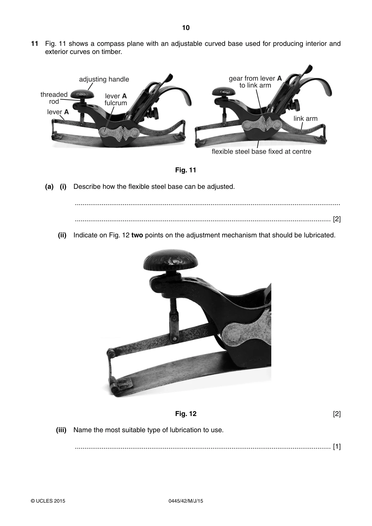
10 0445/42/M/J/15 © UCLES 2015 11 Fig. 11 shows a compass plane with an adjustable curved base used for producing interior and exterior curves on timber. adjusting handle threaded rod lever A lever A fulcrum gear from lever A to link arm link arm flexible steel base fixed at centre Fig. 11 (a) (i) Describe how the flexible steel base can be adjusted. … … [2] (ii) Indicate on Fig. 12 two points on the adjustment mechanism that should be lubricated. Fig. 12 [2] (iii) Name the most suitable type of lubrication to use. … [1]
Question paper, page 11
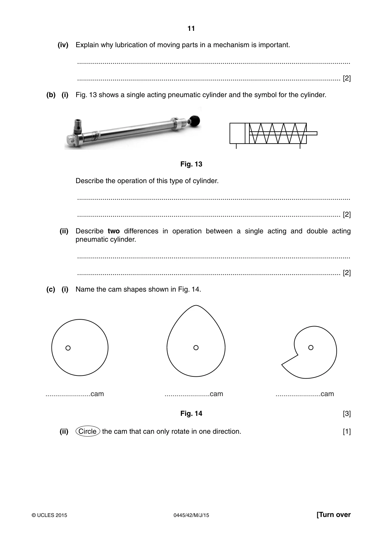
11 0445/42/M/J/15 © UCLES 2015 [Turn over (iv) Explain why lubrication of moving parts in a mechanism is important. … … [2] (b) (i) Fig. 13 shows a single acting pneumatic cylinder and the symbol for the cylinder. Fig. 13 Describe the operation of this type of cylinder. … … [2] (ii) Describe two differences in operation between a single acting and double acting pneumatic cylinder. … … [2] (c) (i) Name the cam shapes shown in Fig. 14. …cam …cam …cam Fig. 14 [3] (ii) Circle the cam that can only rotate in one direction. [1]
Question paper, page 12
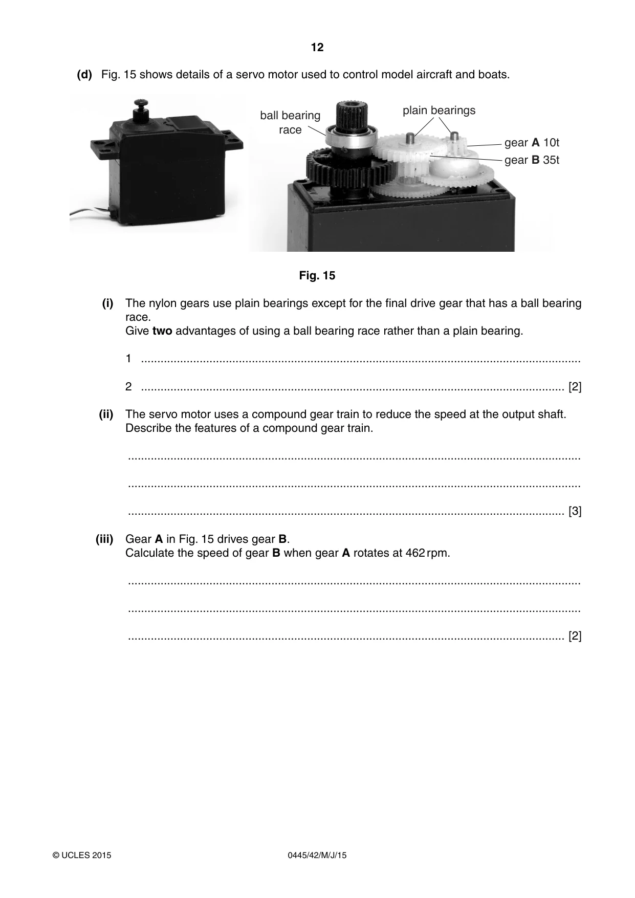
12 0445/42/M/J/15 © UCLES 2015 (d) Fig. 15 shows details of a servo motor used to control model aircraft and boats. ball bearing race plain bearings gear A 10t gear B 35t Fig. 15 (i) The nylon gears use plain bearings except for the final drive gear that has a ball bearing race. Give two advantages of using a ball bearing race rather than a plain bearing. 1 … 2 … [2] (ii) The servo motor uses a compound gear train to reduce the speed at the output shaft. Describe the features of a compound gear train. … … … [3] (iii) Gear A in Fig. 15 drives gear B. Calculate the speed of gear B when gear A rotates at 462 rpm. … … … [2]
Question paper, page 13
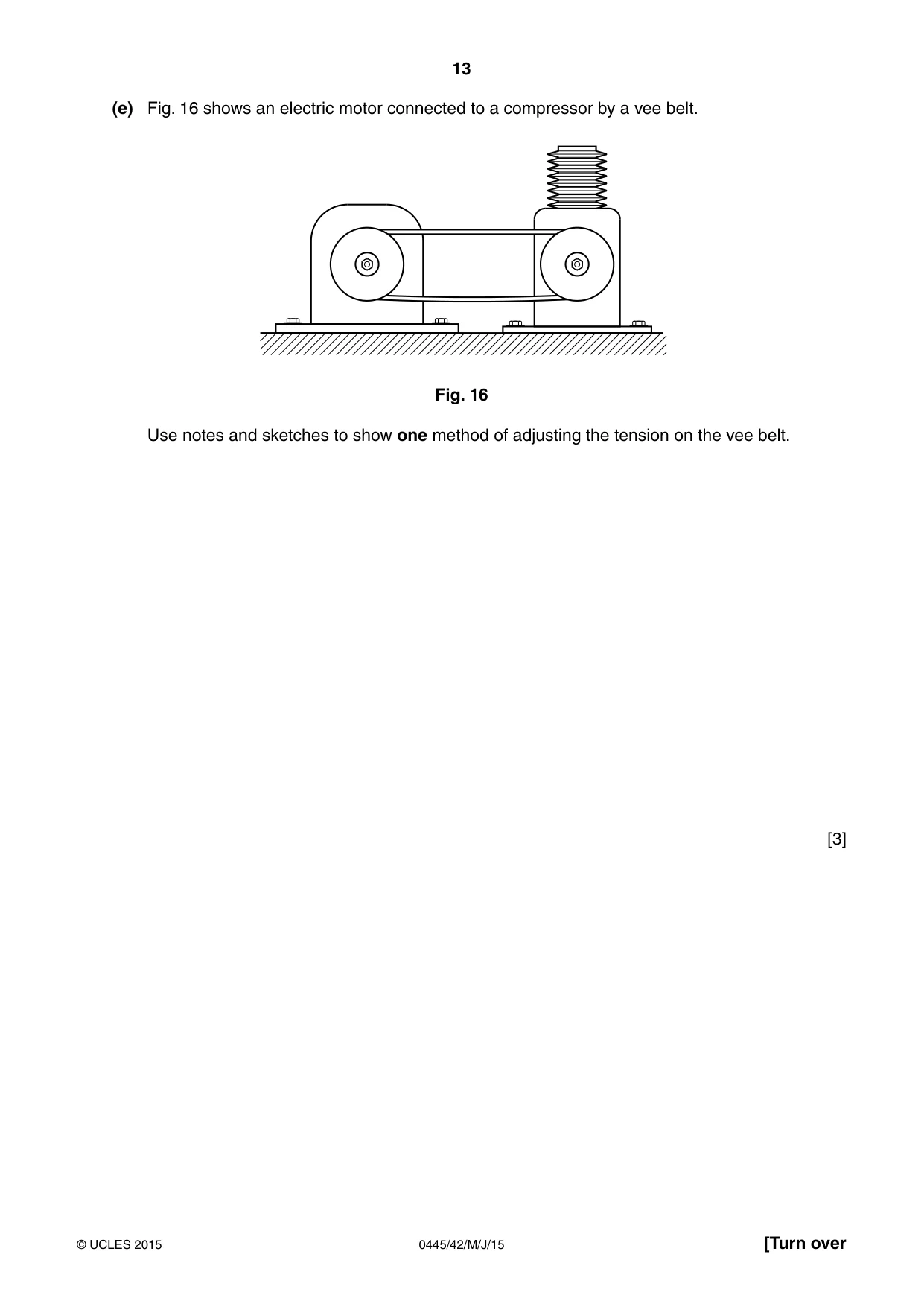
13 0445/42/M/J/15 © UCLES 2015 [Turn over (e) Fig. 16 shows an electric motor connected to a compressor by a vee belt. Fig. 16 Use notes and sketches to show one method of adjusting the tension on the vee belt. [3]
Question paper, page 14
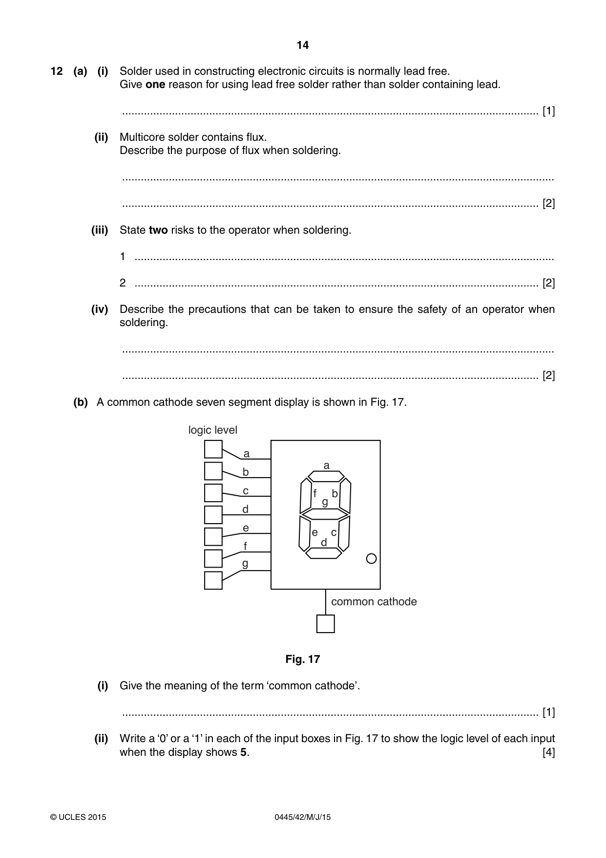
14 0445/42/M/J/15 © UCLES 2015 12 (a) (i) Solder used in constructing electronic circuits is normally lead free. Give one reason for using lead free solder rather than solder containing lead. … [1] (ii) Multicore solder contains flux. Describe the purpose of flux when soldering. … … [2] (iii) State two risks to the operator when soldering. 1 … 2 … [2] (iv) Describe the precautions that can be taken to ensure the safety of an operator when soldering. … … [2] (b) A common cathode seven segment display is shown in Fig. 17. b c e d f g a a b c e d f g common cathode logic level Fig. 17 (i) Give the meaning of the term ‘common cathode’. … [1] (ii) Write a ‘0’ or a ‘1’ in each of the input boxes in Fig. 17 to show the logic level of each input when the display shows 5. [4]
Question paper, page 15
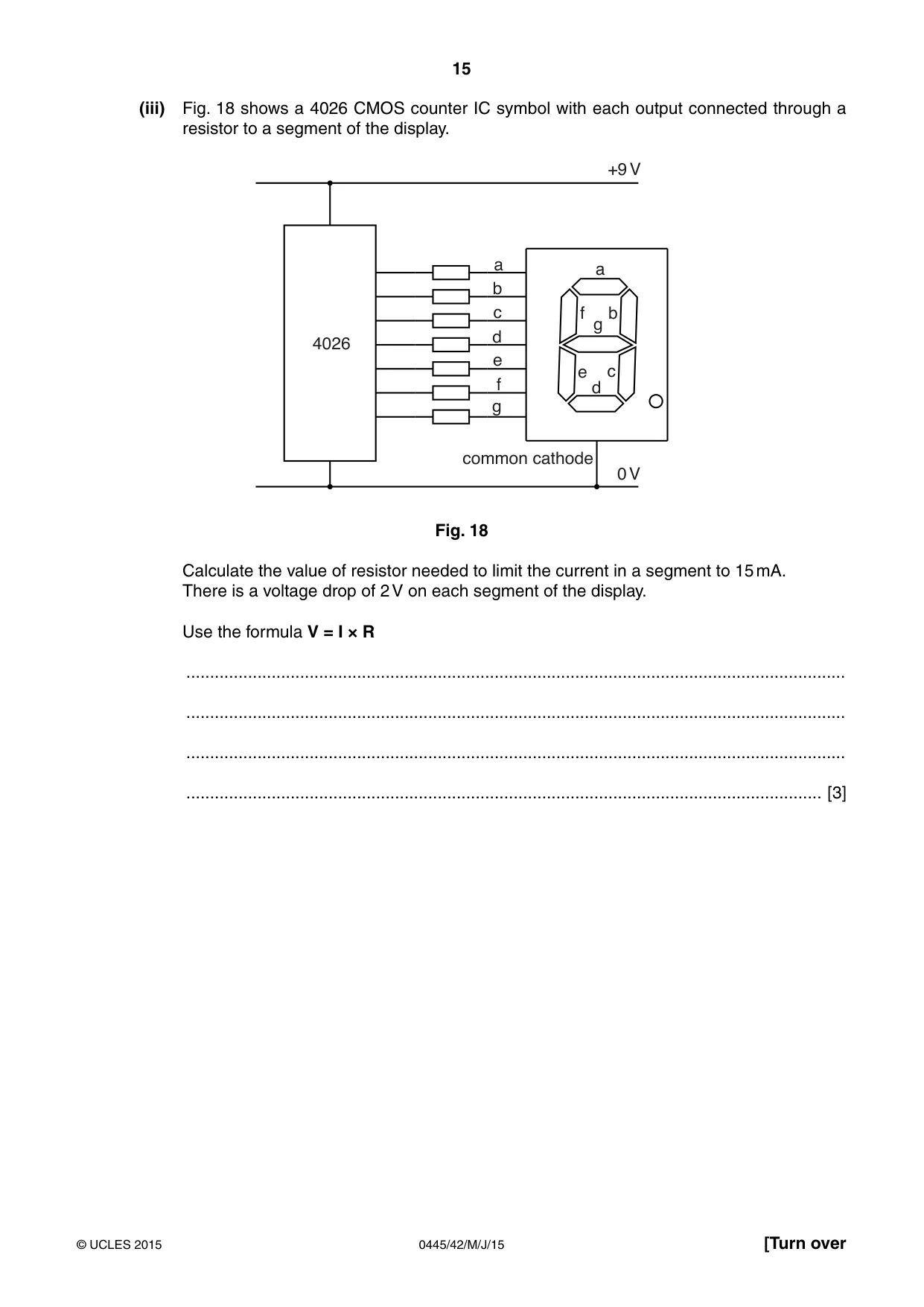
15 0445/42/M/J/15 © UCLES 2015 [Turn over (iii) Fig. 18 shows a 4026 CMOS counter IC symbol with each output connected through a resistor to a segment of the display. b c e d f g a 4026 a b c e d f g common cathode +9 V 0 V Fig. 18 Calculate the value of resistor needed to limit the current in a segment to 15 mA. There is a voltage drop of 2 V on each segment of the display. Use the formula V = I × R … … … … [3]
Question paper, page 16
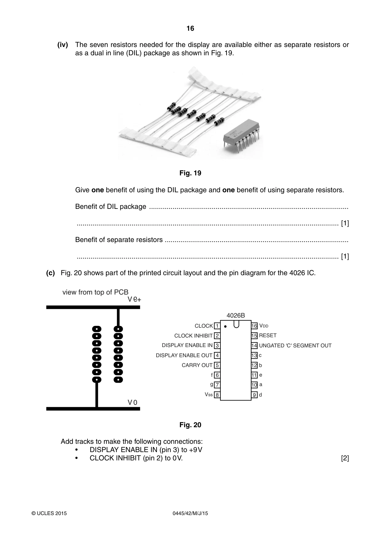
16 0445/42/M/J/15 © UCLES 2015 (iv) The seven resistors needed for the display are available either as separate resistors or as a dual in line (DIL) package as shown in Fig. 19. Fig. 19 Give one benefit of using the DIL package and one benefit of using separate resistors. Benefit of DIL package … … [1] Benefit of separate resistors … … [1] (c) Fig. 20 shows part of the printed circuit layout and the pin diagram for the 4026 IC. CARRY OUT RESET c b a e d CLOCK 1 2 3 4 5 6 7 8 9 10 11 12 13 14 15 16 g f Vss VDD DISPLAY ENABLE IN DISPLAY ENABLE OUT CLOCK INHIBIT UNGATED 'C' SEGMENT OUT 4026B view from top of PCB +9 V 0 V Fig. 20 Add tracks to make the following connections: • DISPLAY ENABLE IN (pin 3) to +9 V • CLOCK INHIBIT (pin 2) to 0 V. [2]
Question paper, page 17
17 0445/42/M/J/15 © UCLES 2015 (d) When the 4026 IC is counting, the reset pin (15) is connected to 0 V. To reset the count to zero the reset pin is connected to +9 V. Fig. 21 shows the components used to operate the reset. Add connections from R1 and SW1 to allow the count to take place and then to be reset. +9 V 0 V to reset pin (15) R1 SW1 Fig. 21 [3] (e) (i) An astable signal can be used as the input to a counter IC. Use notes and sketches to describe an astable signal. [2] (ii) Name an IC that can provide an astable signal. … [1]
Question paper, page 18
18 0445/42/M/J/15 © UCLES 2015 BLANK PAGE
Question paper, page 19
19 0445/42/M/J/15 © UCLES 2015 BLANK PAGE
Question paper, page 20
20 0445/42/M/J/15 © UCLES 2015 Permission to reproduce items where third-party owned material protected by copyright is included has been sought and cleared where possible. Every reasonable effort has been made by the publisher (UCLES) to trace copyright holders, but if any items requiring clearance have unwittingly been included, the publisher will be pleased to make amends at the earliest possible opportunity. To avoid the issue of disclosure of answer-related information to candidates, all copyright acknowledgements are reproduced online in the Cambridge International Examinations Copyright Acknowledgements Booklet. This is produced for each series of examinations and is freely available to download at www.cie.org.uk after the live examination series. Cambridge International Examinations is part of the Cambridge Assessment Group. Cambridge Assessment is the brand name of University of Cambridge Local Examinations Syndicate (UCLES), which is itself a department of the University of Cambridge. BLANK PAGE
Mark scheme, page 1
® IGCSE is the registered trademark of Cambridge International Examinations. CAMBRIDGE INTERNATIONAL EXAMINATIONS Cambridge International General Certificate of Secondary Education MARK SCHEME for the May/June 2015 series 0445 DESIGN AND TECHNOLOGY 0445/42 Paper 4 (Systems and Control), maximum raw mark 50 This mark scheme is published as an aid to teachers and candidates, to indicate the requirements of the examination. It shows the basis on which Examiners were instructed to award marks. It does not indicate the details of the discussions that took place at an Examiners’ meeting before marking began, which would have considered the acceptability of alternative answers. Mark schemes should be read in conjunction with the question paper and the Principal Examiner Report for Teachers. Cambridge will not enter into discussions about these mark schemes. Cambridge is publishing the mark schemes for the May/June 2015 series for most Cambridge IGCSE®, Cambridge International A and AS Level components and some Cambridge O Level components.
Mark scheme, page 2
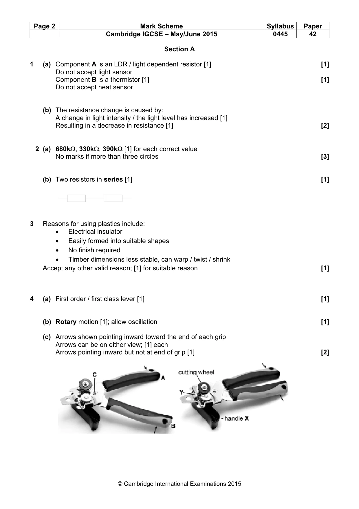
Page 2 Mark Scheme Syllabus Paper Cambridge IGCSE – May/June 2015 0445 42 © Cambridge International Examinations 2015 Section A 1 (a) Component A is an LDR / light dependent resistor [1] [1] Do not accept light sensor Component B is a thermistor [1] [1] Do not accept heat sensor (b) The resistance change is caused by: A change in light intensity / the light level has increased [1] Resulting in a decrease in resistance [1] [2] 2 (a) 680kΩ, 330kΩ, 390kΩ [1] for each correct value No marks if more than three circles [3] (b) Two resistors in series [1] [1] 3 Reasons for using plastics include: • Electrical insulator • Easily formed into suitable shapes • No finish required • Timber dimensions less stable, can warp / twist / shrink Accept any other valid reason; [1] for suitable reason [1] 4 (a) First order / first class lever [1] [1] (b) Rotary motion [1]; allow oscillation [1] (c) Arrows shown pointing inward toward the end of each grip Arrows can be on either view; [1] each Arrows pointing inward but not at end of grip [1] [2]
Mark scheme, page 3
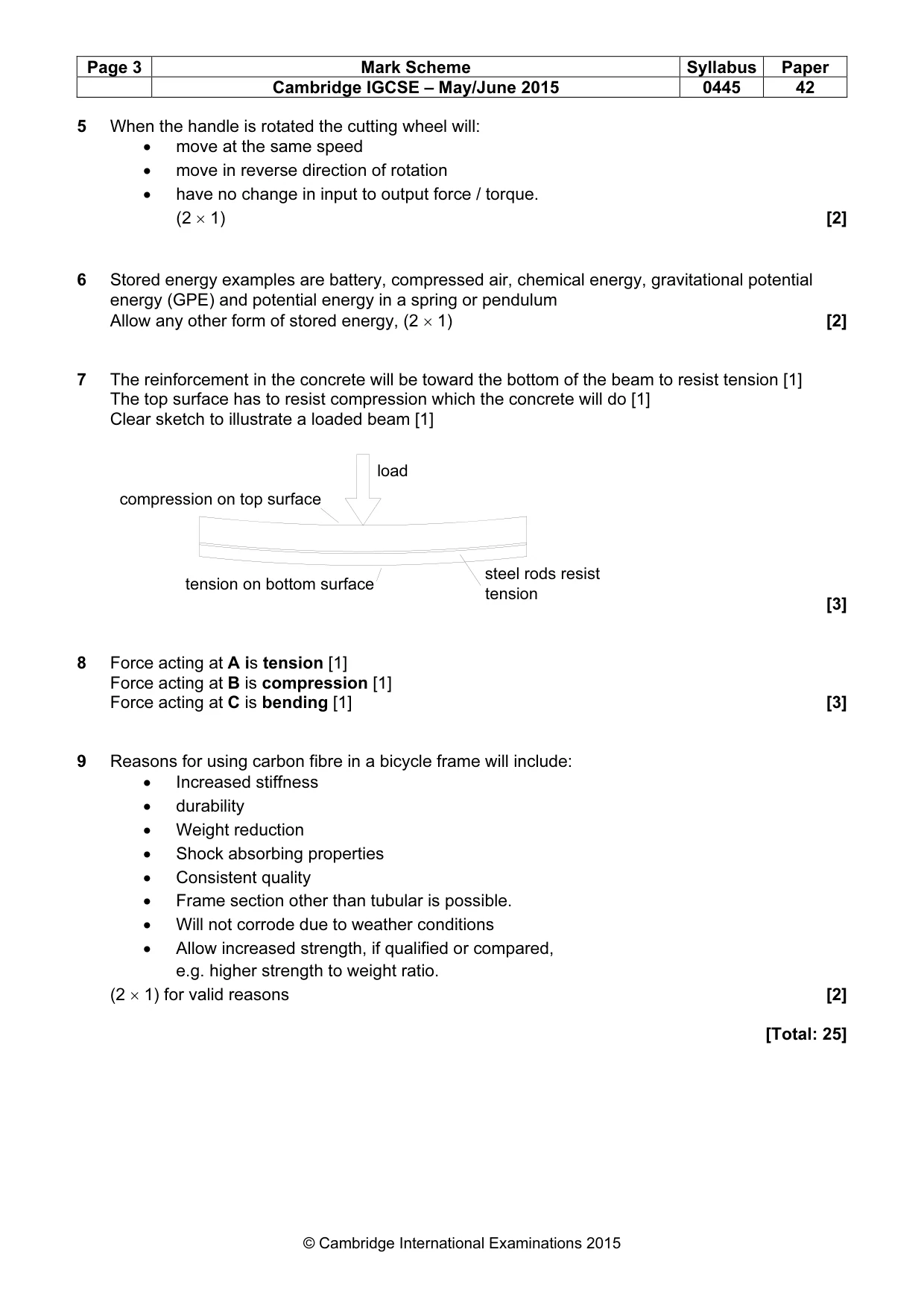
Page 3 Mark Scheme Syllabus Paper Cambridge IGCSE – May/June 2015 0445 42 © Cambridge International Examinations 2015 5 When the handle is rotated the cutting wheel will: • move at the same speed • move in reverse direction of rotation • have no change in input to output force / torque. (2 × 1) [2] 6 Stored energy examples are battery, compressed air, chemical energy, gravitational potential energy (GPE) and potential energy in a spring or pendulum Allow any other form of stored energy, (2 × 1) [2] 7 The reinforcement in the concrete will be toward the bottom of the beam to resist tension [1] The top surface has to resist compression which the concrete will do [1] Clear sketch to illustrate a loaded beam [1] [3] 8 Force acting at A is tension [1] Force acting at B is compression [1] Force acting at C is bending [1] [3] 9 Reasons for using carbon fibre in a bicycle frame will include: • Increased stiffness • durability • Weight reduction • Shock absorbing properties • Consistent quality • Frame section other than tubular is possible. • Will not corrode due to weather conditions • Allow increased strength, if qualified or compared, e.g. higher strength to weight ratio. (2 × 1) for valid reasons [2] [Total: 25] compression on top surface tension on bottom surface steel rods resist tension load
Mark scheme, page 4
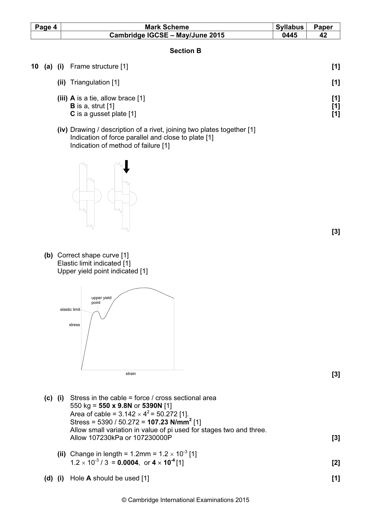
Page 4 Mark Scheme Syllabus Paper Cambridge IGCSE – May/June 2015 0445 42 © Cambridge International Examinations 2015 Section B 10 (a) (i) Frame structure [1] [1] (ii) Triangulation [1] [1] (iii) A is a tie, allow brace [1] [1] B is a, strut [1] [1] C is a gusset plate [1] [1] (iv) Drawing / description of a rivet, joining two plates together [1] Indication of force parallel and close to plate [1] Indication of method of failure [1] [3] (b) Correct shape curve [1] Elastic limit indicated [1] Upper yield point indicated [1] [3] (c) (i) Stress in the cable = force / cross sectional area 550 kg = 550 x 9.8N or 5390N [1] Area of cable = 3.142 × 42 = 50.272 [1]. Stress = 5390 / 50.272 = 107.23 N/mm2 [1] Allow small variation in value of pi used for stages two and three. Allow 107230kPa or 107230000P [3] (ii) Change in length = 1.2mm = 1.2 × 10⁻³ [1] 1.2 × 10⁻³ / 3 = 0.0004, or 4 × 10⁻⁴ [1] [2] (d) (i) Hole A should be used [1] [1] stress strain elastic limit upper yield point
Mark scheme, page 5
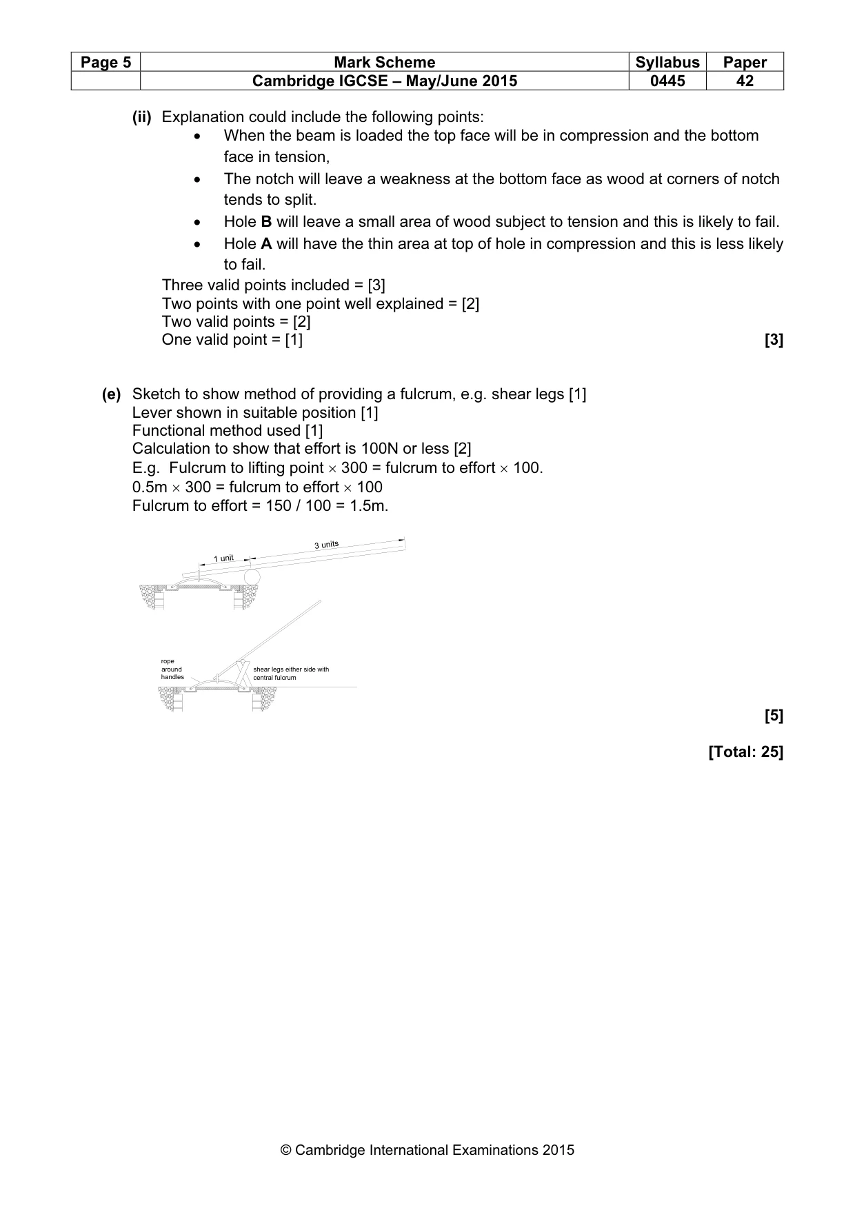
Page 5 Mark Scheme Syllabus Paper Cambridge IGCSE – May/June 2015 0445 42 © Cambridge International Examinations 2015 (ii) Explanation could include the following points: • When the beam is loaded the top face will be in compression and the bottom face in tension, • The notch will leave a weakness at the bottom face as wood at corners of notch tends to split. • Hole B will leave a small area of wood subject to tension and this is likely to fail. • Hole A will have the thin area at top of hole in compression and this is less likely to fail. Three valid points included = [3] Two points with one point well explained = [2] Two valid points = [2] One valid point = [1] [3] (e) Sketch to show method of providing a fulcrum, e.g. shear legs [1] Lever shown in suitable position [1] Functional method used [1] Calculation to show that effort is 100N or less [2] E.g. Fulcrum to lifting point × 300 = fulcrum to effort × 100. 0.5m × 300 = fulcrum to effort × 100 Fulcrum to effort = 150 / 100 = 1.5m. [5] [Total: 25] 3 units 1 unit rope around handles shear legs either side with central fulcrum
Mark scheme, page 6
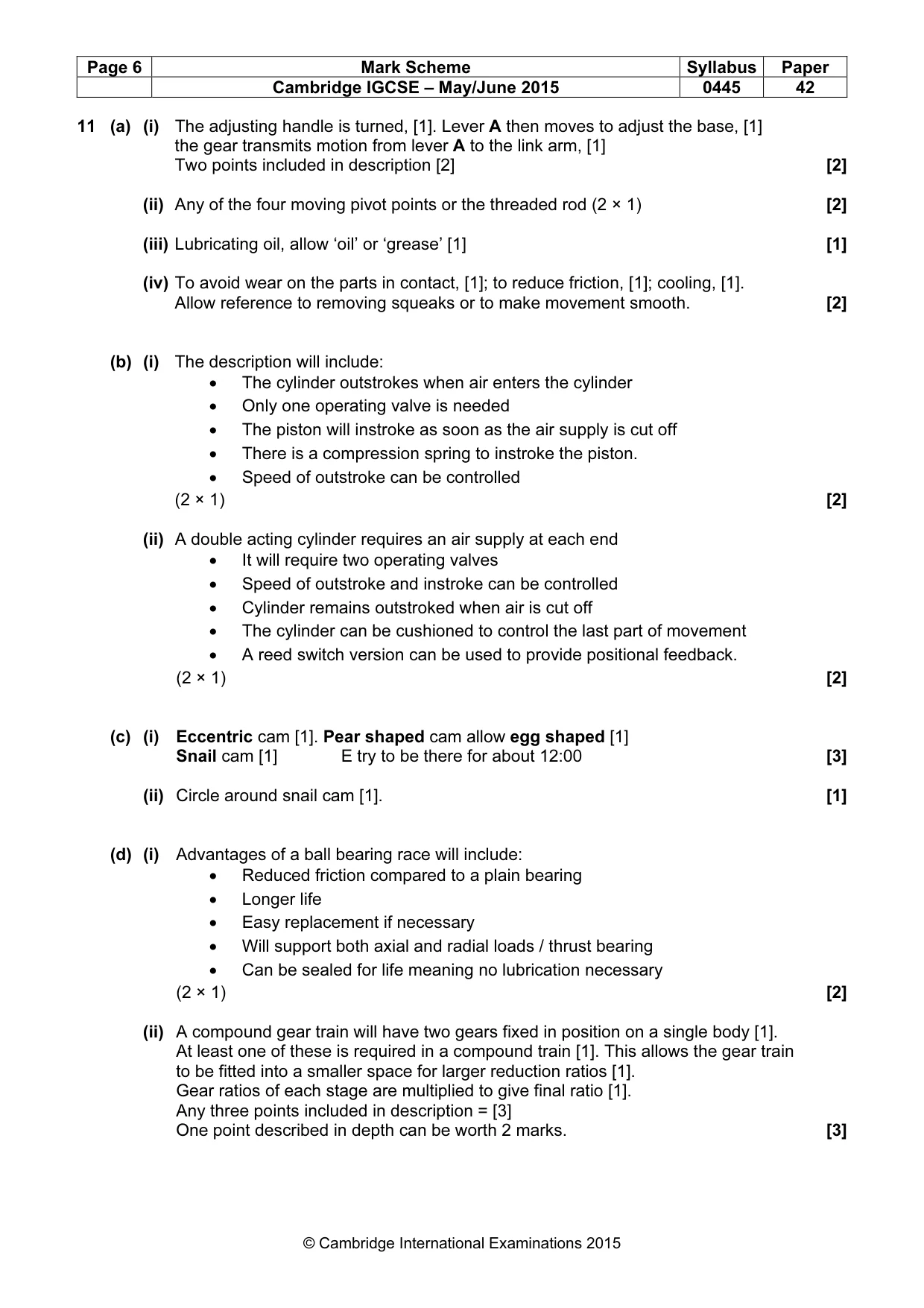
Page 6 Mark Scheme Syllabus Paper Cambridge IGCSE – May/June 2015 0445 42 © Cambridge International Examinations 2015 11 (a) (i) The adjusting handle is turned, [1]. Lever A then moves to adjust the base, [1] the gear transmits motion from lever A to the link arm, [1] Two points included in description [2] [2] (ii) Any of the four moving pivot points or the threaded rod (2 × 1) [2] (iii) Lubricating oil, allow ‘oil’ or ‘grease’ [1] [1] (iv) To avoid wear on the parts in contact, [1]; to reduce friction, [1]; cooling, [1]. Allow reference to removing squeaks or to make movement smooth. [2] (b) (i) The description will include: • The cylinder outstrokes when air enters the cylinder • Only one operating valve is needed • The piston will instroke as soon as the air supply is cut off • There is a compression spring to instroke the piston. • Speed of outstroke can be controlled (2 × 1) [2] (ii) A double acting cylinder requires an air supply at each end • It will require two operating valves • Speed of outstroke and instroke can be controlled • Cylinder remains outstroked when air is cut off • The cylinder can be cushioned to control the last part of movement • A reed switch version can be used to provide positional feedback. (2 × 1) [2] (c) (i) Eccentric cam [1]. Pear shaped cam allow egg shaped [1] Snail cam [1] E try to be there for about 12:00 [3] (ii) Circle around snail cam [1]. [1] (d) (i) Advantages of a ball bearing race will include: • Reduced friction compared to a plain bearing • Longer life • Easy replacement if necessary • Will support both axial and radial loads / thrust bearing • Can be sealed for life meaning no lubrication necessary (2 × 1) [2] (ii) A compound gear train will have two gears fixed in position on a single body [1]. At least one of these is required in a compound train [1]. This allows the gear train to be fitted into a smaller space for larger reduction ratios [1]. Gear ratios of each stage are multiplied to give final ratio [1]. Any three points included in description = [3] One point described in depth can be worth 2 marks. [3]
Mark scheme, page 7
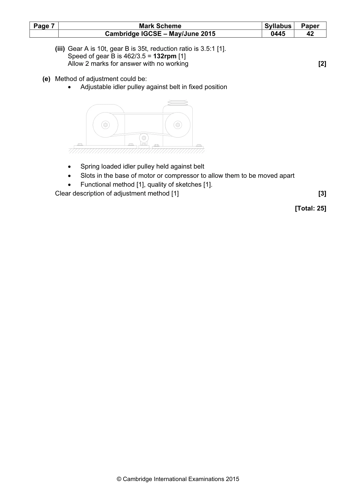
Page 7 Mark Scheme Syllabus Paper Cambridge IGCSE – May/June 2015 0445 42 © Cambridge International Examinations 2015 (iii) Gear A is 10t, gear B is 35t, reduction ratio is 3.5:1 [1]. Speed of gear B is 462/3.5 = 132rpm [1] Allow 2 marks for answer with no working [2] (e) Method of adjustment could be: • Adjustable idler pulley against belt in fixed position • Spring loaded idler pulley held against belt • Slots in the base of motor or compressor to allow them to be moved apart • Functional method [1], quality of sketches [1]. Clear description of adjustment method [1] [3] [Total: 25]
Mark scheme, page 8
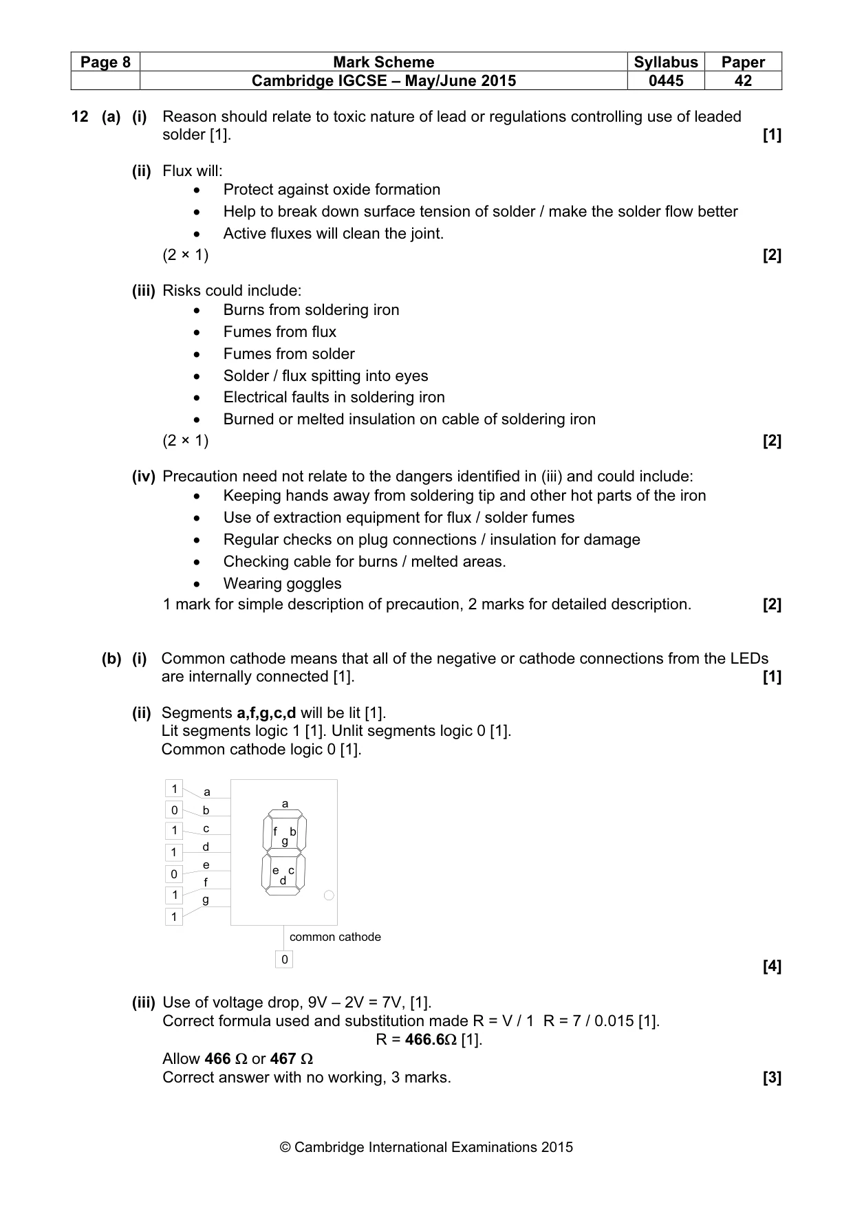
Page 8 Mark Scheme Syllabus Paper Cambridge IGCSE – May/June 2015 0445 42 © Cambridge International Examinations 2015 12 (a) (i) Reason should relate to toxic nature of lead or regulations controlling use of leaded solder [1]. [1] (ii) Flux will: • Protect against oxide formation • Help to break down surface tension of solder / make the solder flow better • Active fluxes will clean the joint. (2 × 1) [2] (iii) Risks could include: • Burns from soldering iron • Fumes from flux • Fumes from solder • Solder / flux spitting into eyes • Electrical faults in soldering iron • Burned or melted insulation on cable of soldering iron (2 × 1) [2] (iv) Precaution need not relate to the dangers identified in (iii) and could include: • Keeping hands away from soldering tip and other hot parts of the iron • Use of extraction equipment for flux / solder fumes • Regular checks on plug connections / insulation for damage • Checking cable for burns / melted areas. • Wearing goggles 1 mark for simple description of precaution, 2 marks for detailed description. [2] (b) (i) Common cathode means that all of the negative or cathode connections from the LEDs are internally connected [1]. [1] (ii) Segments a,f,g,c,d will be lit [1]. Lit segments logic 1 [1]. Unlit segments logic 0 [1]. Common cathode logic 0 [1]. [4] (iii) Use of voltage drop, 9V – 2V = 7V, [1]. Correct formula used and substitution made R = V / 1 R = 7 / 0.015 [1]. R = 466.6Ω [1]. Allow 466 Ω or 467 Ω Correct answer with no working, 3 marks. [3] b c e d f g a a b c e d f g common cathode 1 1 0 0 0 1 1 1
Mark scheme, page 9
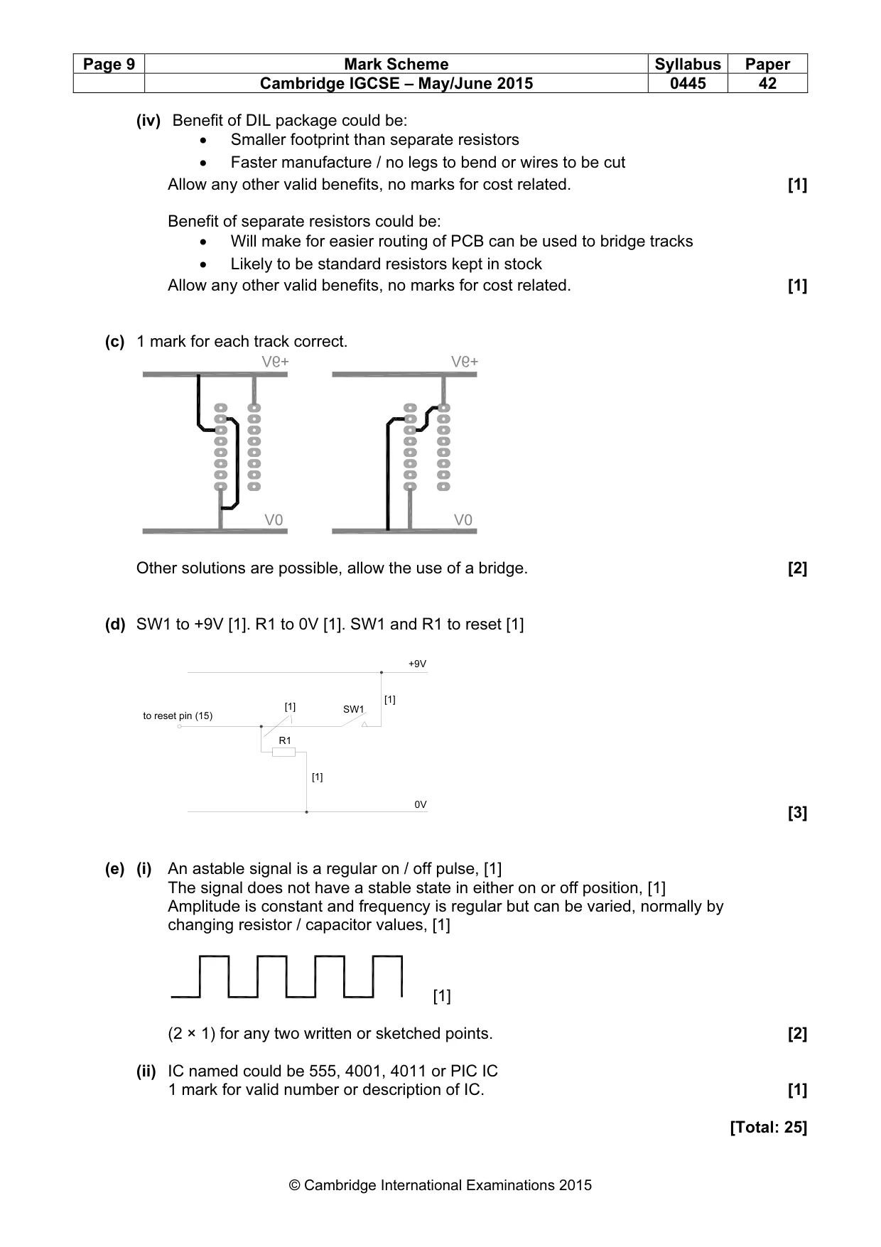
Page 9 Mark Scheme Syllabus Paper Cambridge IGCSE – May/June 2015 0445 42 © Cambridge International Examinations 2015 (iv) Benefit of DIL package could be: • Smaller footprint than separate resistors • Faster manufacture / no legs to bend or wires to be cut Allow any other valid benefits, no marks for cost related. [1] Benefit of separate resistors could be: • Will make for easier routing of PCB can be used to bridge tracks • Likely to be standard resistors kept in stock Allow any other valid benefits, no marks for cost related. [1] (c) 1 mark for each track correct. Other solutions are possible, allow the use of a bridge. [2] (d) SW1 to +9V [1]. R1 to 0V [1]. SW1 and R1 to reset [1] [3] (e) (i) An astable signal is a regular on / off pulse, [1] The signal does not have a stable state in either on or off position, [1] Amplitude is constant and frequency is regular but can be varied, normally by changing resistor / capacitor values, [1] [1] (2 × 1) for any two written or sketched points. [2] (ii) IC named could be 555, 4001, 4011 or PIC IC 1 mark for valid number or description of IC. [1] [Total: 25] +9V 0V to reset pin (15) R1 SW1 [1] [1] [1]
What you needed in this session
Cambridge’s own grade thresholds for 2015 May/June, Paper 4 · Variant 2. A higher threshold means an easier paper — the bar moves with how the cohort did.