Cambridge IGCSE Design and Technology 0445 — 2014 Oct/Nov Paper 4 · Variant 3
0445/43/O/N/14 · 50 marks · ≈56 min
The question paper and its mark scheme, free to read here and free to download. This is Cambridge’s own paper, exactly as it was sat.
Question paper20 pages


Mark scheme8 pages
Answers below. Sit the paper first if you are practising.
Paper as text
Question paper, page 1
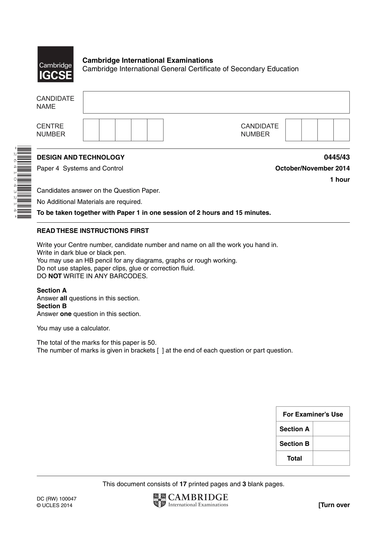
This document consists of 17 printed pages and 3 blank pages. DC (RW) 100047 © UCLES 2014 [Turn over Cambridge International Examinations Cambridge International General Certificate of Secondary Education * 2 6 4 1 0 4 3 2 1 4 * DESIGN AND TECHNOLOGY 0445/43 Paper 4 Systems and Control October/November 2014 1 hour Candidates answer on the Question Paper. No Additional Materials are required. To be taken together with Paper 1 in one session of 2 hours and 15 minutes. READ THESE INSTRUCTIONS FIRST Write your Centre number, candidate number and name on all the work you hand in. Write in dark blue or black pen. You may use an HB pencil for any diagrams, graphs or rough working. Do not use staples, paper clips, glue or correction fluid. DO NOT WRITE IN ANY BARCODES. Section A Answer all questions in this section. Section B Answer one question in this section. You may use a calculator. The total of the marks for this paper is 50. The number of marks is given in brackets [ ] at the end of each question or part question. For Examiner’s Use Section A Section B Total
Question paper, page 2
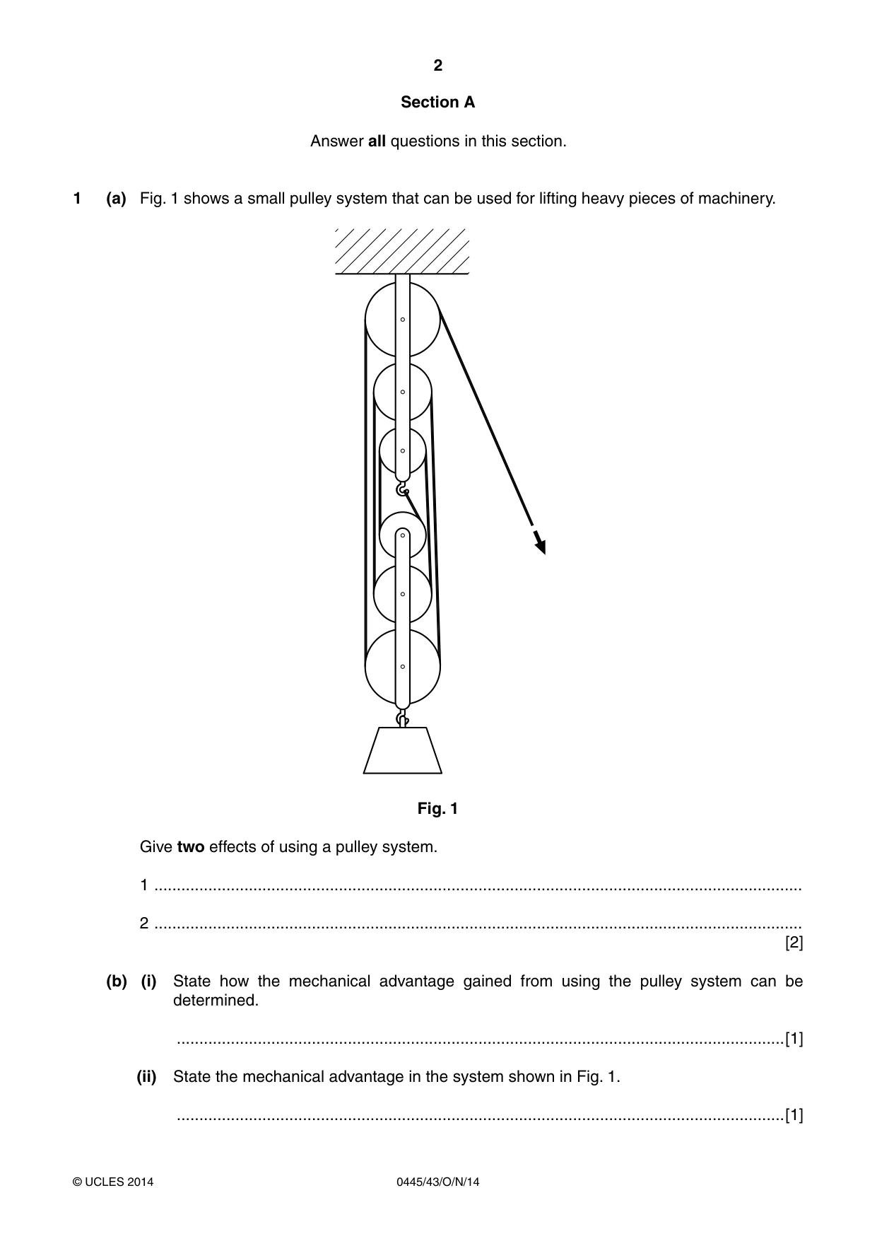
2 0445/43/O/N/14 © UCLES 2014 Section A Answer all questions in this section. 1 (a) Fig. 1 shows a small pulley system that can be used for lifting heavy pieces of machinery. Fig. 1 Give two effects of using a pulley system. 1 … 2 … [2] (b) (i) State how the mechanical advantage gained from using the pulley system can be determined. …[1] (ii) State the mechanical advantage in the system shown in Fig. 1. …[1]
Question paper, page 3
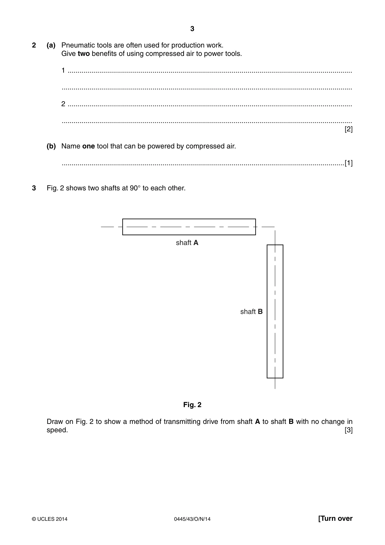
3 0445/43/O/N/14 © UCLES 2014 [Turn over 2 (a) Pneumatic tools are often used for production work. Give two benefits of using compressed air to power tools. 1 … … 2 … … [2] (b) Name one tool that can be powered by compressed air. …[1] 3 Fig. 2 shows two shafts at 90° to each other. shaft A shaft B Fig. 2 Draw on Fig. 2 to show a method of transmitting drive from shaft A to shaft B with no change in speed. [3]
Question paper, page 4
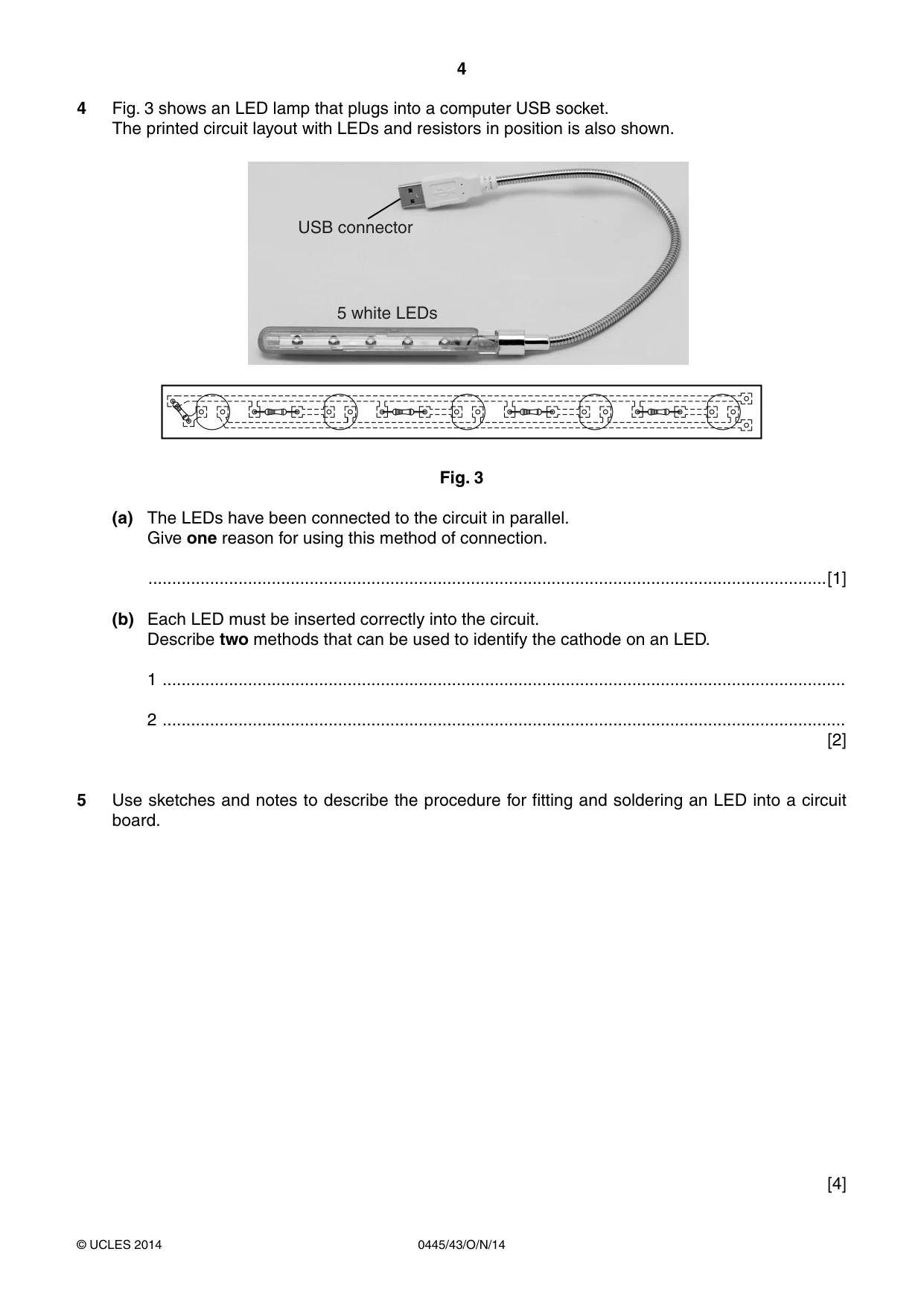
4 0445/43/O/N/14 © UCLES 2014 4 Fig. 3 shows an LED lamp that plugs into a computer USB socket. The printed circuit layout with LEDs and resistors in position is also shown. USB connector 5 white LEDs Fig. 3 (a) The LEDs have been connected to the circuit in parallel. Give one reason for using this method of connection. …[1] (b) Each LED must be inserted correctly into the circuit. Describe two methods that can be used to identify the cathode on an LED. 1 … 2 … [2] 5 Use sketches and notes to describe the procedure for fitting and soldering an LED into a circuit board. [4]
Question paper, page 5
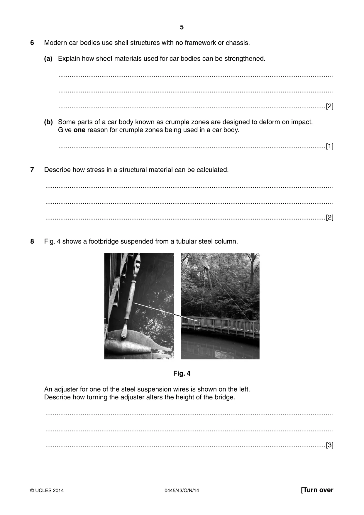
5 0445/43/O/N/14 © UCLES 2014 [Turn over 6 Modern car bodies use shell structures with no framework or chassis. (a) Explain how sheet materials used for car bodies can be strengthened. … … …[2] (b) Some parts of a car body known as crumple zones are designed to deform on impact. Give one reason for crumple zones being used in a car body. …[1] 7 Describe how stress in a structural material can be calculated. … … …[2] 8 Fig. 4 shows a footbridge suspended from a tubular steel column. Fig. 4 An adjuster for one of the steel suspension wires is shown on the left. Describe how turning the adjuster alters the height of the bridge. … … …[3]
Question paper, page 6
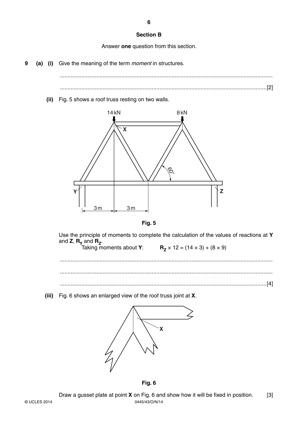
6 0445/43/O/N/14 © UCLES 2014 Section B Answer one question from this section. 9 (a) (i) Give the meaning of the term moment in structures. … …[2] (ii) Fig. 5 shows a roof truss resting on two walls. 60° Y Z 3 m 3 m 14 kN 8 kN X Fig. 5 Use the principle of moments to complete the calculation of the values of reactions at Y and Z, RY and RZ. Taking moments about Y: RZ × 12 = (14 × 3) + (8 × 9) … … …[4] (iii) Fig. 6 shows an enlarged view of the roof truss joint at X. X Fig. 6 Draw a gusset plate at point X on Fig. 6 and show how it will be fixed in position. [3]
Question paper, page 7
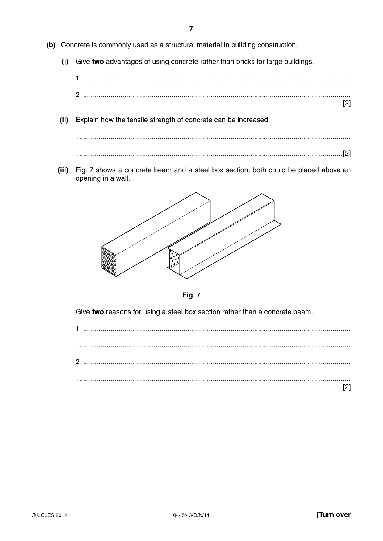
7 0445/43/O/N/14 © UCLES 2014 [Turn over (b) Concrete is commonly used as a structural material in building construction. (i) Give two advantages of using concrete rather than bricks for large buildings. 1 … 2 … [2] (ii) Explain how the tensile strength of concrete can be increased. … …[2] (iii) Fig. 7 shows a concrete beam and a steel box section, both could be placed above an opening in a wall. Fig. 7 Give two reasons for using a steel box section rather than a concrete beam. 1 … … 2 … … [2]
Question paper, page 8
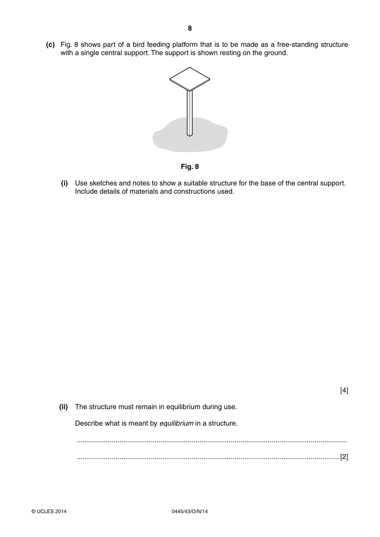
8 0445/43/O/N/14 © UCLES 2014 (c) Fig. 8 shows part of a bird feeding platform that is to be made as a free-standing structure with a single central support. The support is shown resting on the ground. Fig. 8 (i) Use sketches and notes to show a suitable structure for the base of the central support. Include details of materials and constructions used. [4] (ii) The structure must remain in equilibrium during use. Describe what is meant by equilibrium in a structure. … …[2]
Question paper, page 9
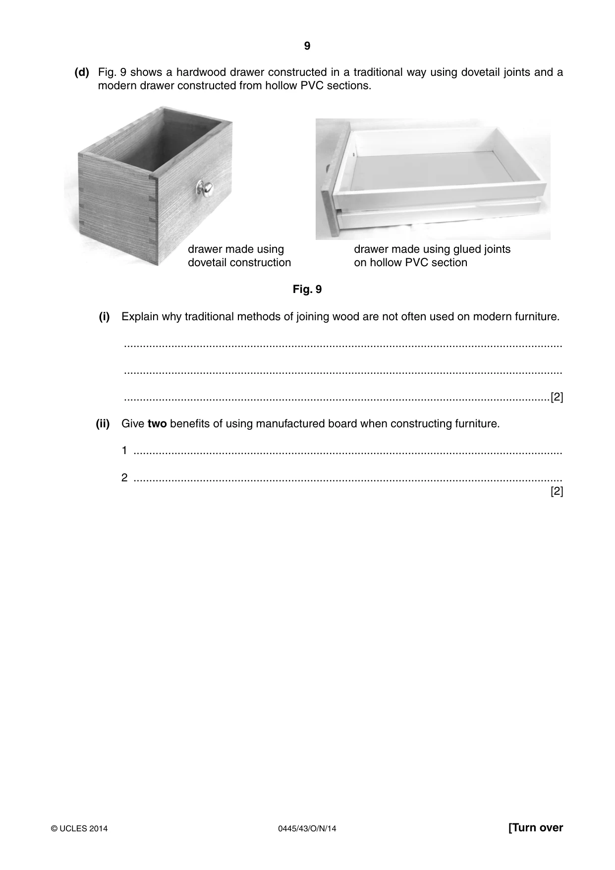
9 0445/43/O/N/14 © UCLES 2014 [Turn over (d) Fig. 9 shows a hardwood drawer constructed in a traditional way using dovetail joints and a modern drawer constructed from hollow PVC sections. drawer made using dovetail construction drawer made using glued joints on hollow PVC section Fig. 9 (i) Explain why traditional methods of joining wood are not often used on modern furniture. … … …[2] (ii) Give two benefits of using manufactured board when constructing furniture. 1 … 2 … [2]
Question paper, page 10
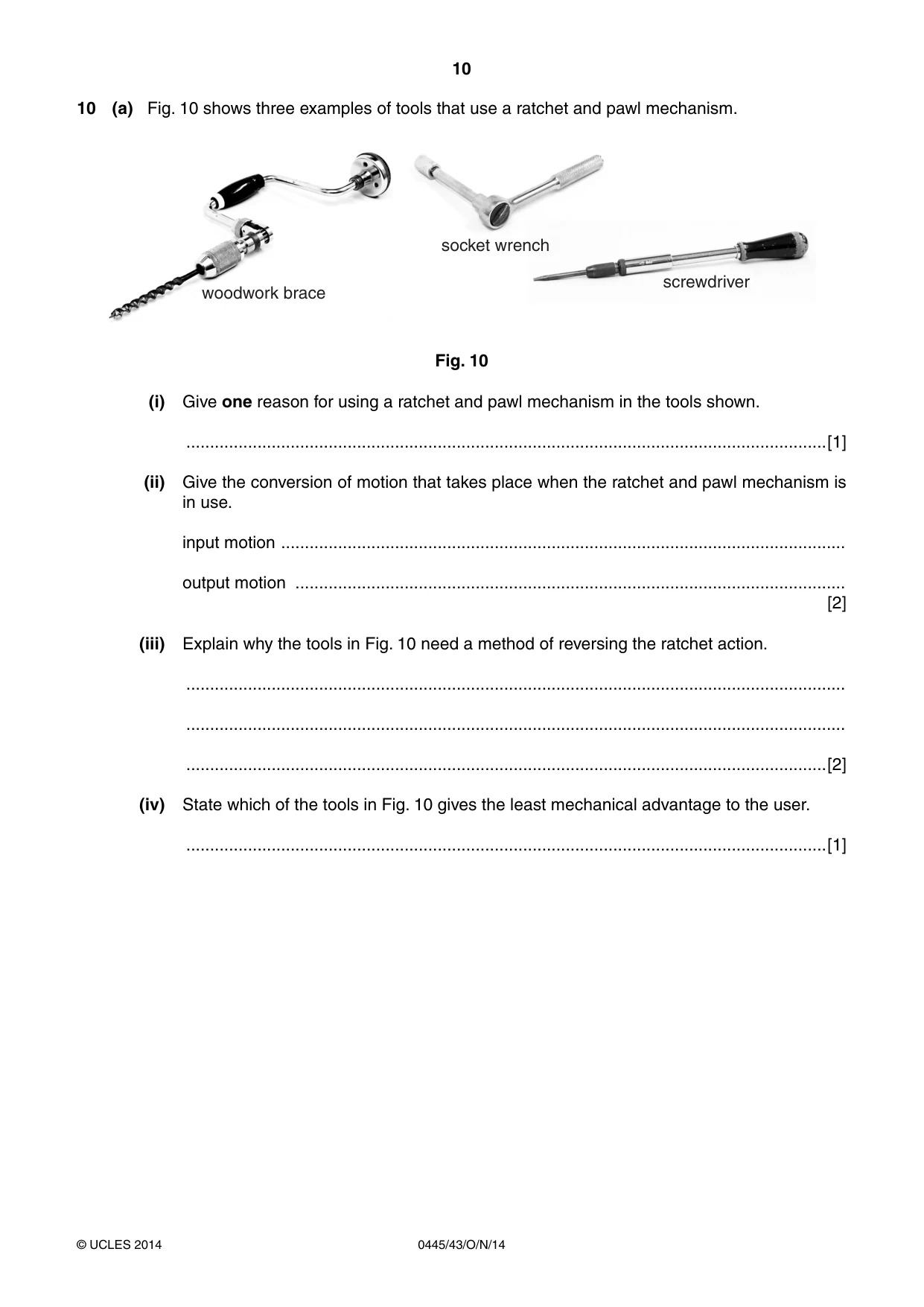
10 0445/43/O/N/14 © UCLES 2014 10 (a) Fig. 10 shows three examples of tools that use a ratchet and pawl mechanism. woodwork brace screwdriver socket wrench Fig. 10 (i) Give one reason for using a ratchet and pawl mechanism in the tools shown. …[1] (ii) Give the conversion of motion that takes place when the ratchet and pawl mechanism is in use. input motion … output motion … [2] (iii) Explain why the tools in Fig. 10 need a method of reversing the ratchet action. … … …[2] (iv) State which of the tools in Fig. 10 gives the least mechanical advantage to the user. …[1]
Question paper, page 11
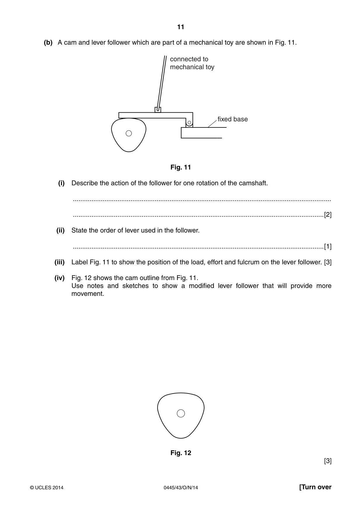
11 0445/43/O/N/14 © UCLES 2014 [Turn over (b) A cam and lever follower which are part of a mechanical toy are shown in Fig. 11. connected to mechanical toy fixed base Fig. 11 (i) Describe the action of the follower for one rotation of the camshaft. … …[2] (ii) State the order of lever used in the follower. …[1] (iii) Label Fig. 11 to show the position of the load, effort and fulcrum on the lever follower. [3] (iv) Fig. 12 shows the cam outline from Fig. 11. Use notes and sketches to show a modified lever follower that will provide more movement. Fig. 12 [3]
Question paper, page 12
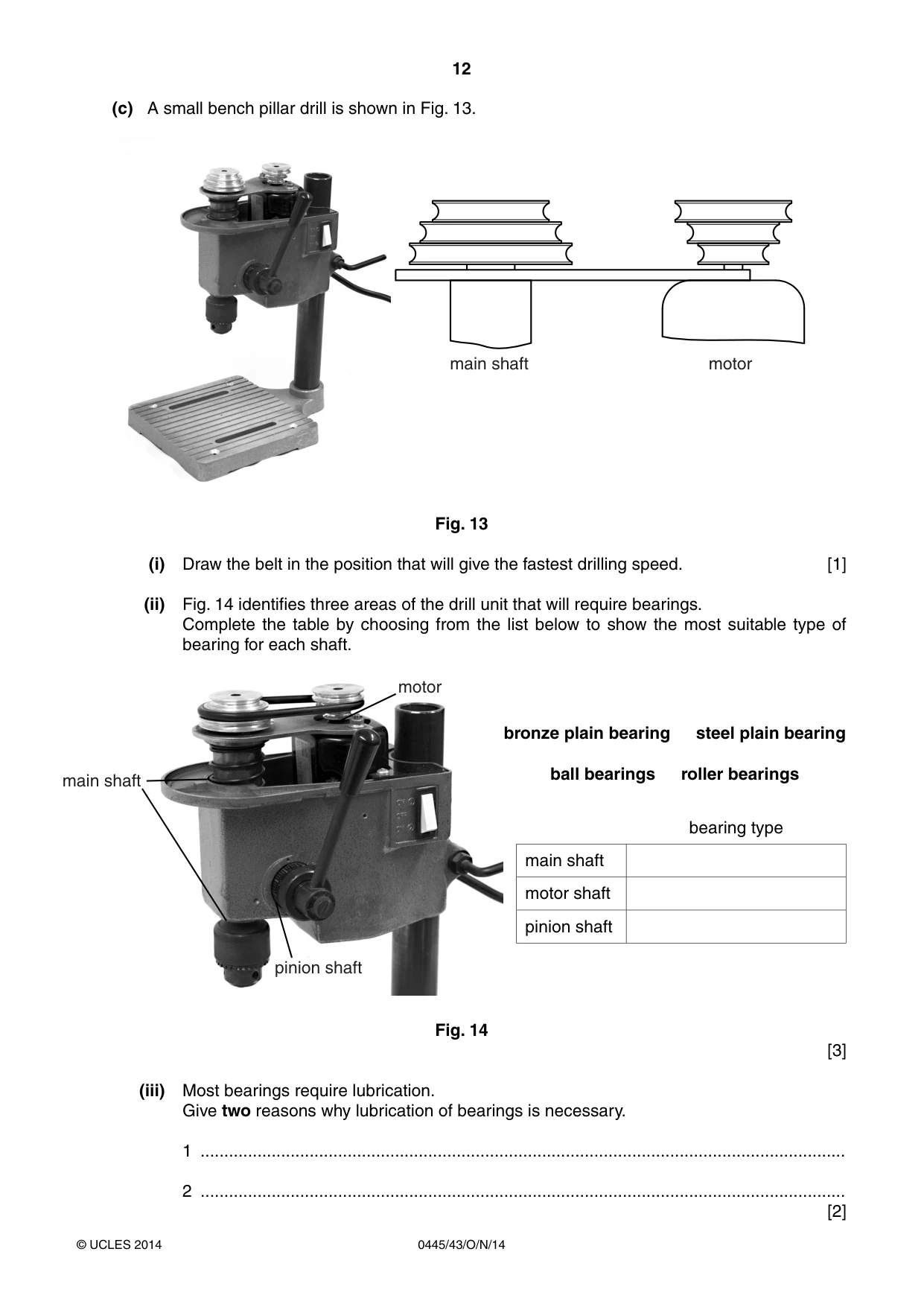
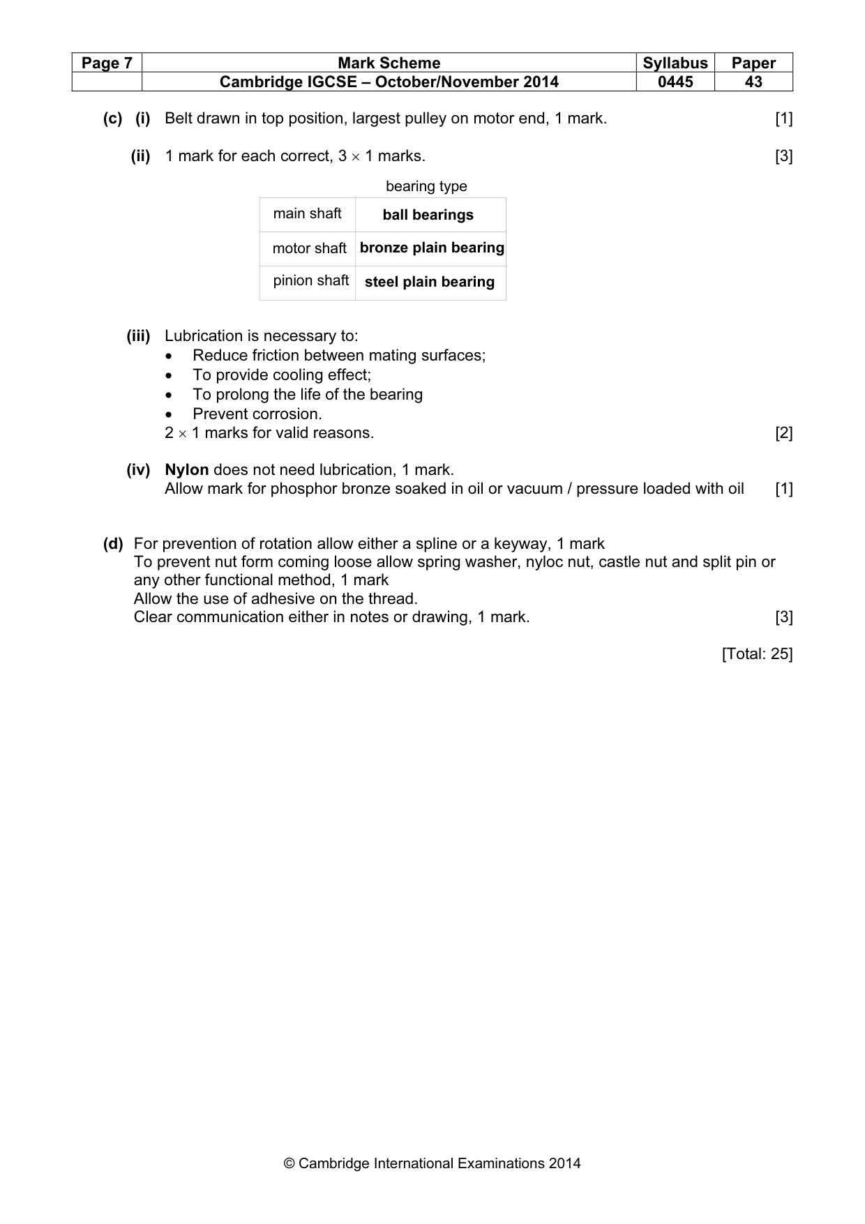
12 0445/43/O/N/14 © UCLES 2014 (c) A small bench pillar drill is shown in Fig. 13. main shaft motor Fig. 13 (i) Draw the belt in the position that will give the fastest drilling speed. [1] (ii) Fig. 14 identifies three areas of the drill unit that will require bearings. Complete the table by choosing from the list below to show the most suitable type of bearing for each shaft. main shaft motor pinion shaft bronze plain bearing steel plain bearing ball bearings roller bearings bearing type main shaft motor shaft pinion shaft Fig. 14 [3] (iii) Most bearings require lubrication. Give two reasons why lubrication of bearings is necessary. 1 … 2 … [2]
Question paper, page 13
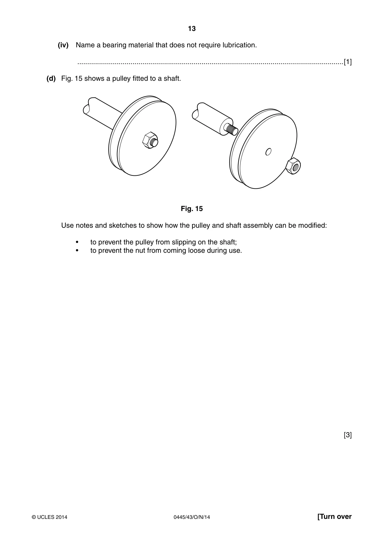
13 0445/43/O/N/14 © UCLES 2014 [Turn over (iv) Name a bearing material that does not require lubrication. …[1] (d) Fig. 15 shows a pulley fitted to a shaft. Fig. 15 Use notes and sketches to show how the pulley and shaft assembly can be modified: • to prevent the pulley from slipping on the shaft; • to prevent the nut from coming loose during use. [3]
Question paper, page 14
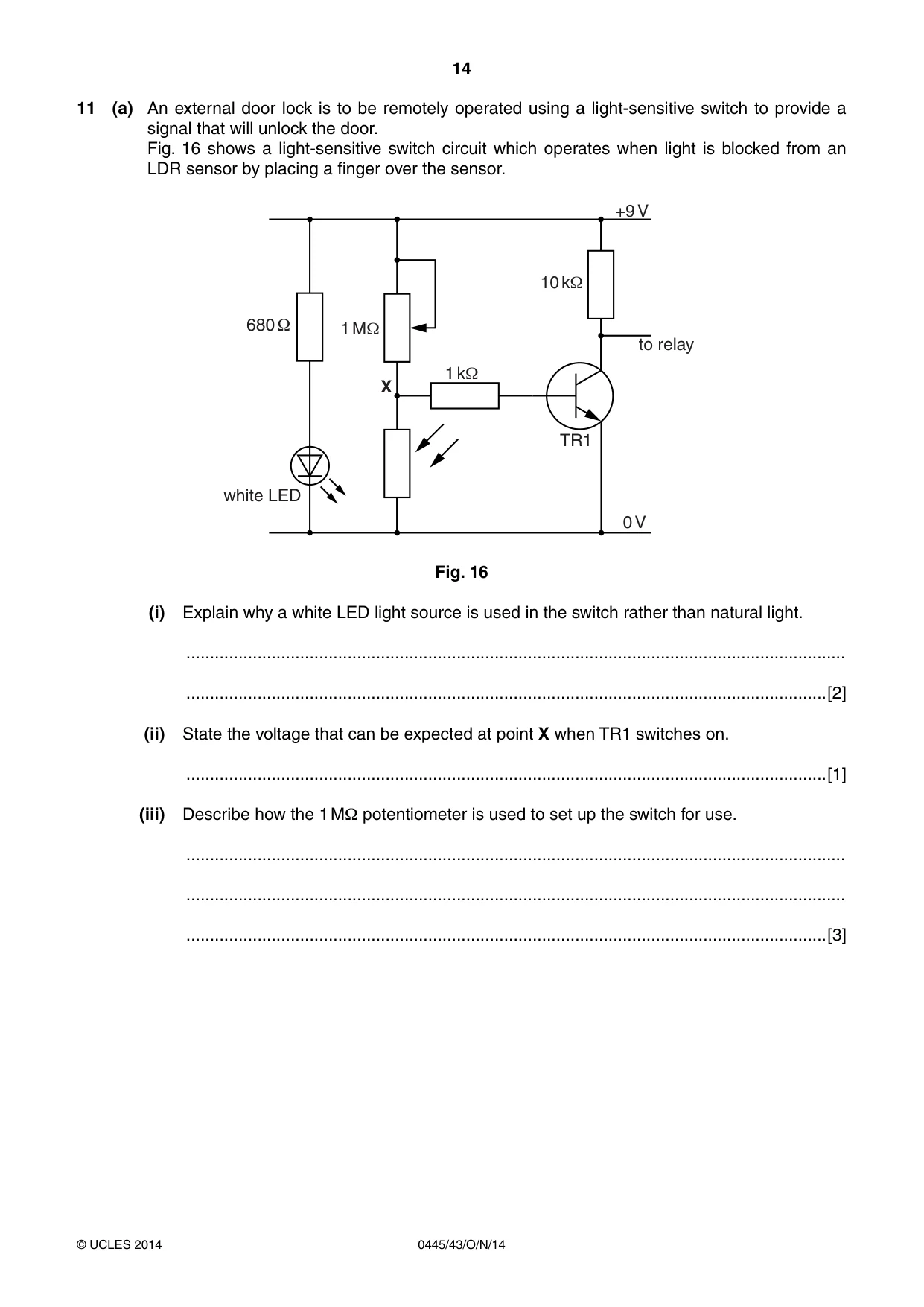
14 0445/43/O/N/14 © UCLES 2014 11 (a) An external door lock is to be remotely operated using a light-sensitive switch to provide a signal that will unlock the door. Fig. 16 shows a light-sensitive switch circuit which operates when light is blocked from an LDR sensor by placing a finger over the sensor. 1 M1 10 k1 680 1 1 k1 TR1 +9 V 0 V X white LED to relay Fig. 16 (i) Explain why a white LED light source is used in the switch rather than natural light. … …[2] (ii) State the voltage that can be expected at point X when TR1 switches on. …[1] (iii) Describe how the 1 MΩ potentiometer is used to set up the switch for use. … … …[3]
Question paper, page 15
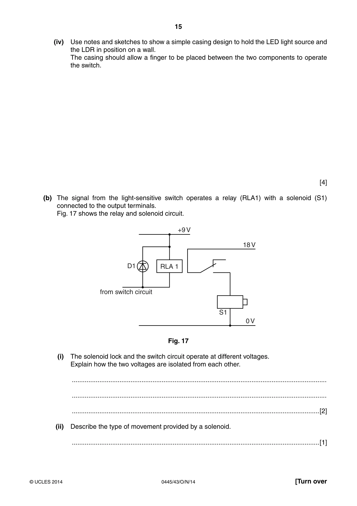
15 0445/43/O/N/14 © UCLES 2014 [Turn over (iv) Use notes and sketches to show a simple casing design to hold the LED light source and the LDR in position on a wall. The casing should allow a finger to be placed between the two components to operate the switch. [4] (b) The signal from the light-sensitive switch operates a relay (RLA1) with a solenoid (S1) connected to the output terminals. Fig. 17 shows the relay and solenoid circuit. S1 D1 +9 V 0 V 18 V from switch circuit RLA 1 Fig. 17 (i) The solenoid lock and the switch circuit operate at different voltages. Explain how the two voltages are isolated from each other. … … …[2] (ii) Describe the type of movement provided by a solenoid. …[1]
Question paper, page 16
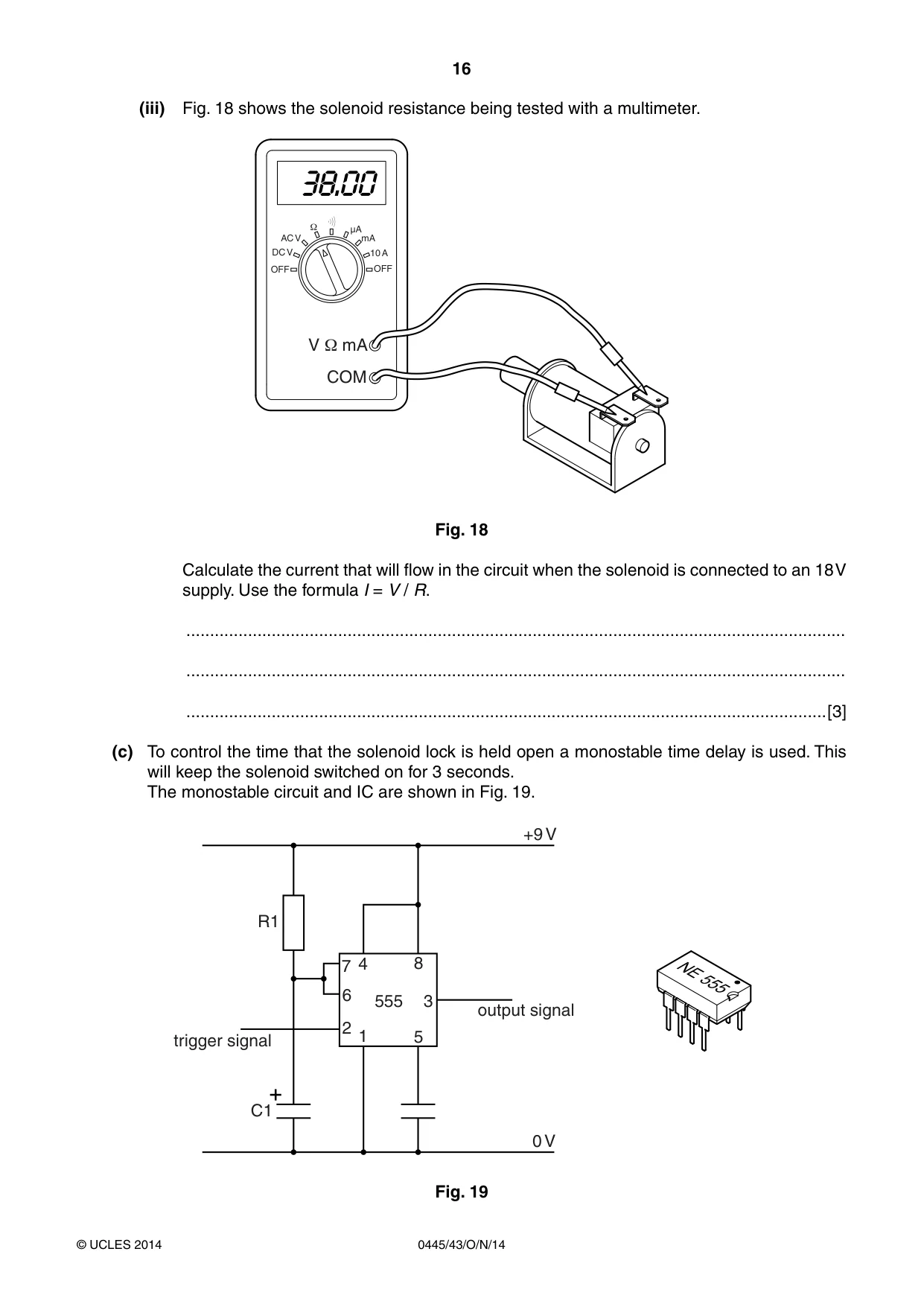
16 0445/43/O/N/14 © UCLES 2014 (iii) Fig. 18 shows the solenoid resistance being tested with a multimeter. OFF DC V OFF 10 A 1 AC V µA mA V 1 mA COM Fig. 18 Calculate the current that will flow in the circuit when the solenoid is connected to an 18 V supply. Use the formula I = V / R. … … …[3] (c) To control the time that the solenoid lock is held open a monostable time delay is used. This will keep the solenoid switched on for 3 seconds. The monostable circuit and IC are shown in Fig. 19. 555 1 2 3 4 5 6 7 8 R1 C1 trigger signal output signal 0 V +9 V Fig. 19
Question paper, page 17
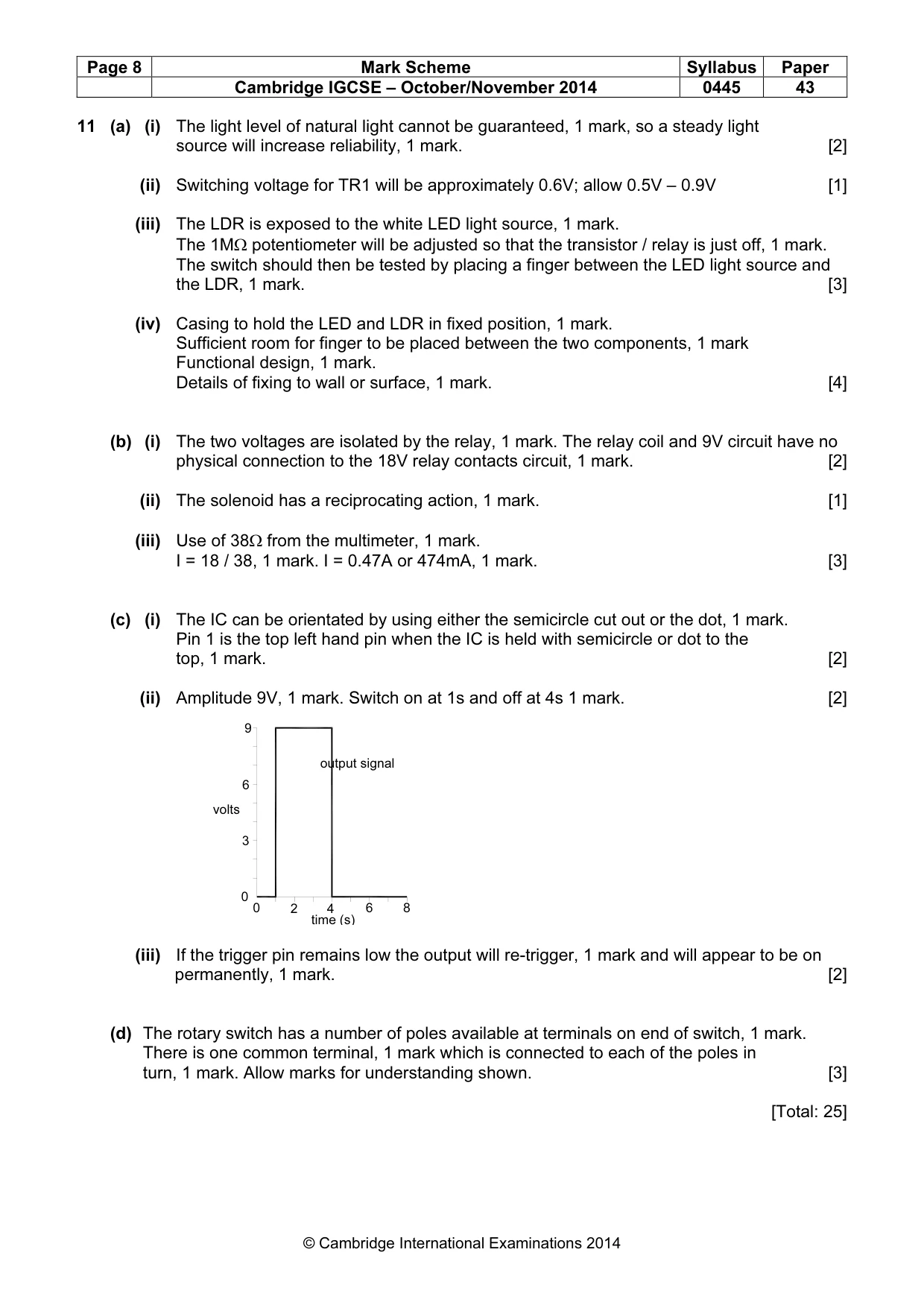
17 0445/43/O/N/14 © UCLES 2014 (i) The 555 timer IC is manufactured in an 8 pin dil package. Describe how the user of the package can identify pin 1 of the IC. … …[2] (ii) When the trigger pin (2) goes from high to low, the output pin (3) goes high for 3 seconds. Complete the graph below to show the output signal. time (s) volts trigger signal 0 3 6 9 0 2 4 6 8 output signal time (s) volts 0 3 6 9 0 2 4 6 8 [2] (iii) Describe what will happen if the trigger pin remains low for longer than 3 seconds. … … …[2] (d) The delay can be altered by using a rotary switch to connect different resistors to the circuit. Fig. 20 shows a rotary switch. Use notes and sketches to explain how a rotary switch works. Fig. 20 [3]
Question paper, page 18
18 0445/43/O/N/14 © UCLES 2014 BLANK PAGE
Question paper, page 19
19 0445/43/O/N/14 © UCLES 2014 BLANK PAGE
Question paper, page 20
20 0445/43/O/N/14 © UCLES 2014 Permission to reproduce items where third-party owned material protected by copyright is included has been sought and cleared where possible. Every reasonable effort has been made by the publisher (UCLES) to trace copyright holders, but if any items requiring clearance have unwittingly been included, the publisher will be pleased to make amends at the earliest possible opportunity. Cambridge International Examinations is part of the Cambridge Assessment Group. Cambridge Assessment is the brand name of University of Cambridge Local Examinations Syndicate (UCLES), which is itself a department of the University of Cambridge. BLANK PAGE
Mark scheme, page 1
® IGCSE is the registered trademark of Cambridge International Examinations. CAMBRIDGE INTERNATIONAL EXAMINATIONS Cambridge International General Certificate of Secondary Education MARK SCHEME for the October/November 2014 series 0445 DESIGN AND TECHNOLOGY 0445/43 Paper 43 (Systems and Control), maximum raw mark 50 This mark scheme is published as an aid to teachers and candidates, to indicate the requirements of the examination. It shows the basis on which Examiners were instructed to award marks. It does not indicate the details of the discussions that took place at an Examiners’ meeting before marking began, which would have considered the acceptability of alternative answers. Mark schemes should be read in conjunction with the question paper and the Principal Examiner Report for Teachers. Cambridge will not enter into discussions about these mark schemes. Cambridge is publishing the mark schemes for the October/November 2014 series for most Cambridge IGCSE®, Cambridge International A and AS Level components and some Cambridge O Level components.
Mark scheme, page 2
Page 2 Mark Scheme Syllabus Paper Cambridge IGCSE – October/November 2014 0445 43 © Cambridge International Examinations 2014 Section A 1 (a) Effects of using a pulley are: • Mechanical advantage if more than one pulley is used in the system • Allow ‘mechanical advantage’ • The load can be lifted using less effort • A greater length of rope passes through the hands of the user than the distance moved by the load. 2 × 1 marks for any two valid effects [2] (b) (i) The mechanical advantage can be determined by: • counting the lengths of rope that the load is divided between • counting the number of pulleys • dividing load by effort. 1 mark for suitable advantage [1] (ii) The mechanical advantage is 6:1 [1] 2 (a) Benefits of pneumatic tools could be: • Compressed air can be stored easily • It is safe to use and in use compared to electricity • Compressed air is easily transported around a factory • Reduced level of pollution • It can be used in hazardous environments • Will provide reciprocating movement easily. 2 × 1 marks for valid benefits [2] (b) Tool could be bench drill, hand drill, lifting / handling equipment, impact wrench, stapler, angle grinder, metal shears 1 mark for a valid choice of tool. [1] 3 Use of bevel gears, 1 mark Gears of same size, 1 mark Gears shown in correct relative positions on the shafts, 1 mark 3 × 1 marks [3] 4 (a) Reason for parallel connection could be: • LEDs do not all go out if one breaks • Even spread of light • Not a high enough voltage for operating in series due to voltage drop across each LED. 1 mark for suitable reason. [1] (b) Cathode can be identified by: • Flat on the casing • Shorter cathode • Use of a multimeter • Trial and error in a breadboard. 2 × 1 marks for suitable methods [2]
Mark scheme, page 3
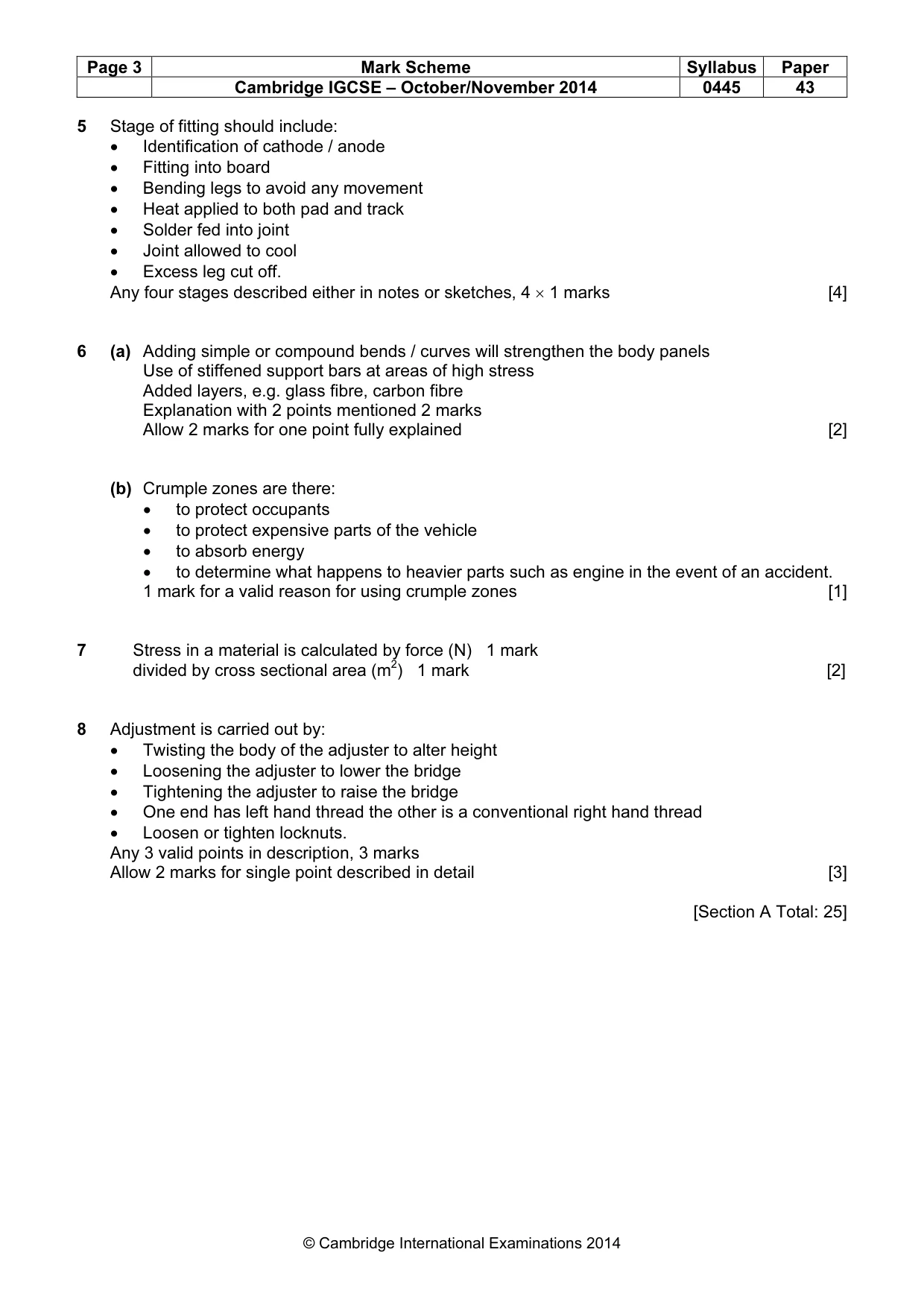
Page 3 Mark Scheme Syllabus Paper Cambridge IGCSE – October/November 2014 0445 43 © Cambridge International Examinations 2014 5 Stage of fitting should include: • Identification of cathode / anode • Fitting into board • Bending legs to avoid any movement • Heat applied to both pad and track • Solder fed into joint • Joint allowed to cool • Excess leg cut off. Any four stages described either in notes or sketches, 4 × 1 marks [4] 6 (a) Adding simple or compound bends / curves will strengthen the body panels Use of stiffened support bars at areas of high stress Added layers, e.g. glass fibre, carbon fibre Explanation with 2 points mentioned 2 marks Allow 2 marks for one point fully explained [2] (b) Crumple zones are there: • to protect occupants • to protect expensive parts of the vehicle • to absorb energy • to determine what happens to heavier parts such as engine in the event of an accident. 1 mark for a valid reason for using crumple zones [1] 7 Stress in a material is calculated by force (N) 1 mark divided by cross sectional area (m2) 1 mark [2] 8 Adjustment is carried out by: • Twisting the body of the adjuster to alter height • Loosening the adjuster to lower the bridge • Tightening the adjuster to raise the bridge • One end has left hand thread the other is a conventional right hand thread • Loosen or tighten locknuts. Any 3 valid points in description, 3 marks Allow 2 marks for single point described in detail [3] [Section A Total: 25]
Mark scheme, page 4
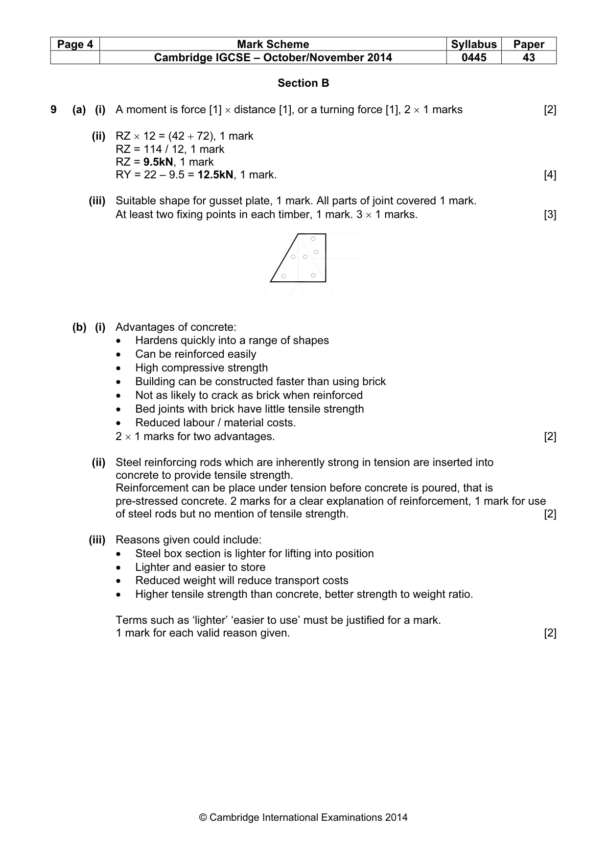
Page 4 Mark Scheme Syllabus Paper Cambridge IGCSE – October/November 2014 0445 43 © Cambridge International Examinations 2014 Section B 9 (a) (i) A moment is force [1] × distance [1], or a turning force [1], 2 × 1 marks [2] (ii) RZ × 12 = (42 + 72), 1 mark RZ = 114 / 12, 1 mark RZ = 9.5kN, 1 mark RY = 22 – 9.5 = 12.5kN, 1 mark. [4] (iii) Suitable shape for gusset plate, 1 mark. All parts of joint covered 1 mark. At least two fixing points in each timber, 1 mark. 3 × 1 marks. [3] (b) (i) Advantages of concrete: • Hardens quickly into a range of shapes • Can be reinforced easily • High compressive strength • Building can be constructed faster than using brick • Not as likely to crack as brick when reinforced • Bed joints with brick have little tensile strength • Reduced labour / material costs. 2 × 1 marks for two advantages. [2] (ii) Steel reinforcing rods which are inherently strong in tension are inserted into concrete to provide tensile strength. Reinforcement can be place under tension before concrete is poured, that is pre-stressed concrete. 2 marks for a clear explanation of reinforcement, 1 mark for use of steel rods but no mention of tensile strength. [2] (iii) Reasons given could include: • Steel box section is lighter for lifting into position • Lighter and easier to store • Reduced weight will reduce transport costs • Higher tensile strength than concrete, better strength to weight ratio. Terms such as ‘lighter’ ‘easier to use’ must be justified for a mark. 1 mark for each valid reason given. [2]
Mark scheme, page 5
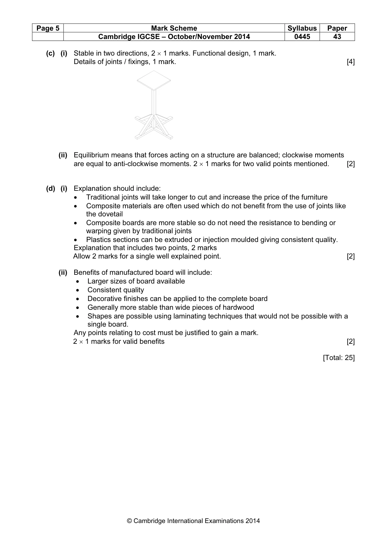
Page 5 Mark Scheme Syllabus Paper Cambridge IGCSE – October/November 2014 0445 43 © Cambridge International Examinations 2014 (c) (i) Stable in two directions, 2 × 1 marks. Functional design, 1 mark. Details of joints / fixings, 1 mark. [4] (ii) Equilibrium means that forces acting on a structure are balanced; clockwise moments are equal to anti-clockwise moments. 2 × 1 marks for two valid points mentioned. [2] (d) (i) Explanation should include: • Traditional joints will take longer to cut and increase the price of the furniture • Composite materials are often used which do not benefit from the use of joints like the dovetail • Composite boards are more stable so do not need the resistance to bending or warping given by traditional joints • Plastics sections can be extruded or injection moulded giving consistent quality. Explanation that includes two points, 2 marks Allow 2 marks for a single well explained point. [2] (ii) Benefits of manufactured board will include: • Larger sizes of board available • Consistent quality • Decorative finishes can be applied to the complete board • Generally more stable than wide pieces of hardwood • Shapes are possible using laminating techniques that would not be possible with a single board. Any points relating to cost must be justified to gain a mark. 2 × 1 marks for valid benefits [2] [Total: 25]
Mark scheme, page 6
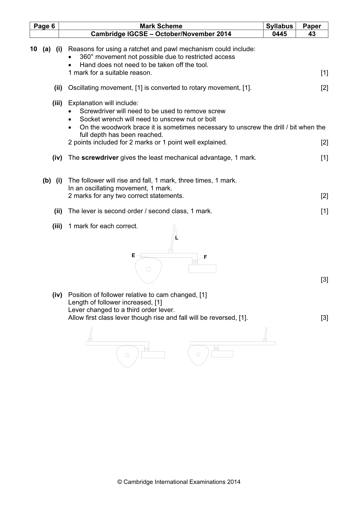
Page 6 Mark Scheme Syllabus Paper Cambridge IGCSE – October/November 2014 0445 43 © Cambridge International Examinations 2014 10 (a) (i) Reasons for using a ratchet and pawl mechanism could include: • 360° movement not possible due to restricted access • Hand does not need to be taken off the tool. 1 mark for a suitable reason. [1] (ii) Oscillating movement, [1] is converted to rotary movement, [1]. [2] (iii) Explanation will include: • Screwdriver will need to be used to remove screw • Socket wrench will need to unscrew nut or bolt • On the woodwork brace it is sometimes necessary to unscrew the drill / bit when the full depth has been reached. 2 points included for 2 marks or 1 point well explained. [2] (iv) The screwdriver gives the least mechanical advantage, 1 mark. [1] (b) (i) The follower will rise and fall, 1 mark, three times, 1 mark. In an oscillating movement, 1 mark. 2 marks for any two correct statements. [2] (ii) The lever is second order / second class, 1 mark. [1] (iii) 1 mark for each correct. [3] (iv) Position of follower relative to cam changed, [1] Length of follower increased, [1] Lever changed to a third order lever. Allow first class lever though rise and fall will be reversed, [1]. [3] L F E
Mark scheme, page 7
Page 7 Mark Scheme Syllabus Paper Cambridge IGCSE – October/November 2014 0445 43 © Cambridge International Examinations 2014 (c) (i) Belt drawn in top position, largest pulley on motor end, 1 mark. [1] (ii) 1 mark for each correct, 3 × 1 marks. [3] (iii) Lubrication is necessary to: • Reduce friction between mating surfaces; • To provide cooling effect; • To prolong the life of the bearing • Prevent corrosion. 2 × 1 marks for valid reasons. [2] (iv) Nylon does not need lubrication, 1 mark. Allow mark for phosphor bronze soaked in oil or vacuum / pressure loaded with oil [1] (d) For prevention of rotation allow either a spline or a keyway, 1 mark To prevent nut form coming loose allow spring washer, nyloc nut, castle nut and split pin or any other functional method, 1 mark Allow the use of adhesive on the thread. Clear communication either in notes or drawing, 1 mark. [3] [Total: 25] main shaft motor shaft pinion shaft bronze plain bearing steel plain bearing ball bearings bearing type
Mark scheme, page 8
Page 8 Mark Scheme Syllabus Paper Cambridge IGCSE – October/November 2014 0445 43 © Cambridge International Examinations 2014 11 (a) (i) The light level of natural light cannot be guaranteed, 1 mark, so a steady light source will increase reliability, 1 mark. [2] (ii) Switching voltage for TR1 will be approximately 0.6V; allow 0.5V – 0.9V [1] (iii) The LDR is exposed to the white LED light source, 1 mark. The 1MΩ potentiometer will be adjusted so that the transistor / relay is just off, 1 mark. The switch should then be tested by placing a finger between the LED light source and the LDR, 1 mark. [3] (iv) Casing to hold the LED and LDR in fixed position, 1 mark. Sufficient room for finger to be placed between the two components, 1 mark Functional design, 1 mark. Details of fixing to wall or surface, 1 mark. [4] (b) (i) The two voltages are isolated by the relay, 1 mark. The relay coil and 9V circuit have no physical connection to the 18V relay contacts circuit, 1 mark. [2] (ii) The solenoid has a reciprocating action, 1 mark. [1] (iii) Use of 38Ω from the multimeter, 1 mark. I = 18 / 38, 1 mark. I = 0.47A or 474mA, 1 mark. [3] (c) (i) The IC can be orientated by using either the semicircle cut out or the dot, 1 mark. Pin 1 is the top left hand pin when the IC is held with semicircle or dot to the top, 1 mark. [2] (ii) Amplitude 9V, 1 mark. Switch on at 1s and off at 4s 1 mark. [2] (iii) If the trigger pin remains low the output will re-trigger, 1 mark and will appear to be on permanently, 1 mark. [2] (d) The rotary switch has a number of poles available at terminals on end of switch, 1 mark. There is one common terminal, 1 mark which is connected to each of the poles in turn, 1 mark. Allow marks for understanding shown. [3] [Total: 25] output signal time (s) volts 0 3 6 9 0 2 4 6 8
What you needed in this session
Cambridge’s own grade thresholds for 2014 Oct/Nov, Paper 4 · Variant 3. A higher threshold means an easier paper — the bar moves with how the cohort did.