Cambridge IGCSE Design and Technology 0445 — 2014 May/June Paper 4 · Variant 3
0445/43/M/J/14 · 50 marks · ≈56 min
The question paper and its mark scheme, free to read here and free to download. This is Cambridge’s own paper, exactly as it was sat.
Question paper20 pages


Mark scheme
No mark scheme is in the library for this paper.
Paper as text
Question paper, page 1
This document consists of 17 printed pages and 3 blank pages. DC (NF/SW) 90511 © UCLES 2014 [Turn over Cambridge International Examinations Cambridge International General Certificate of Secondary Education * 8 9 3 6 1 2 2 0 2 6 * DESIGN AND TECHNOLOGY 0445/43 Paper 4 Systems and Control May/June 2014 1 hour Candidates answer on the Question Paper. No Additional Materials are required. To be taken together with Paper 1 in one session of 2 hours and 15 minutes. READ THESE INSTRUCTIONS FIRST Write your Centre number, candidate number and name on all the work you hand in. Write in dark blue or black pen. You may use an HB pencil for any diagrams or graphs. Do not use staples, paper clips, glue or correction fluid. DO NOT WRITE IN ANY BARCODES. You may use a calculator. Section A Answer all questions. Section B Answer one question. At the end of the examination, fasten all your work securely together. The number of marks is given in brackets [ ] at the end of each question or part question. For Examiner’s Use Section A Section B Total
Question paper, page 2
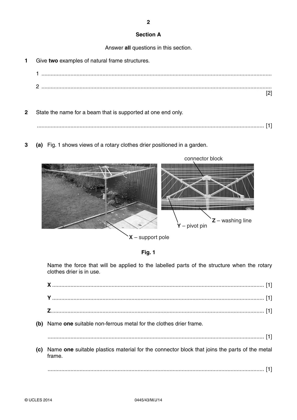
2 0445/43/M/J/14 © UCLES 2014 Section A Answer all questions in this section. 1 Give two examples of natural frame structures. 1 … 2 … [2] 2 State the name for a beam that is supported at one end only. … [1] 3 (a) Fig. 1 shows views of a rotary clothes drier positioned in a garden. connector block Z – washing line Y – pivot pin X – support pole Fig. 1 Name the force that will be applied to the labelled parts of the structure when the rotary clothes drier is in use. X … [1] Y … [1] Z… [1] (b) Name one suitable non-ferrous metal for the clothes drier frame. … [1] (c) Name one suitable plastics material for the connector block that joins the parts of the metal frame. … [1]
Question paper, page 3
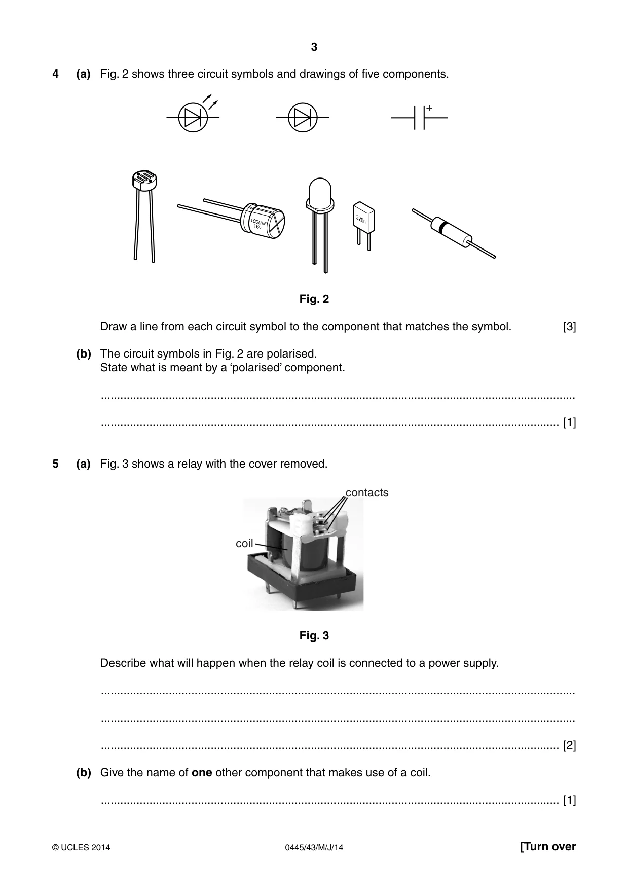
3 0445/43/M/J/14 © UCLES 2014 [Turn over 4 (a) Fig. 2 shows three circuit symbols and drawings of five components. + Fig. 2 Draw a line from each circuit symbol to the component that matches the symbol. [3] (b) The circuit symbols in Fig. 2 are polarised. State what is meant by a ‘polarised’ component. … … [1] 5 (a) Fig. 3 shows a relay with the cover removed. contacts coil Fig. 3 Describe what will happen when the relay coil is connected to a power supply. … … … [2] (b) Give the name of one other component that makes use of a coil. … [1]
Question paper, page 4
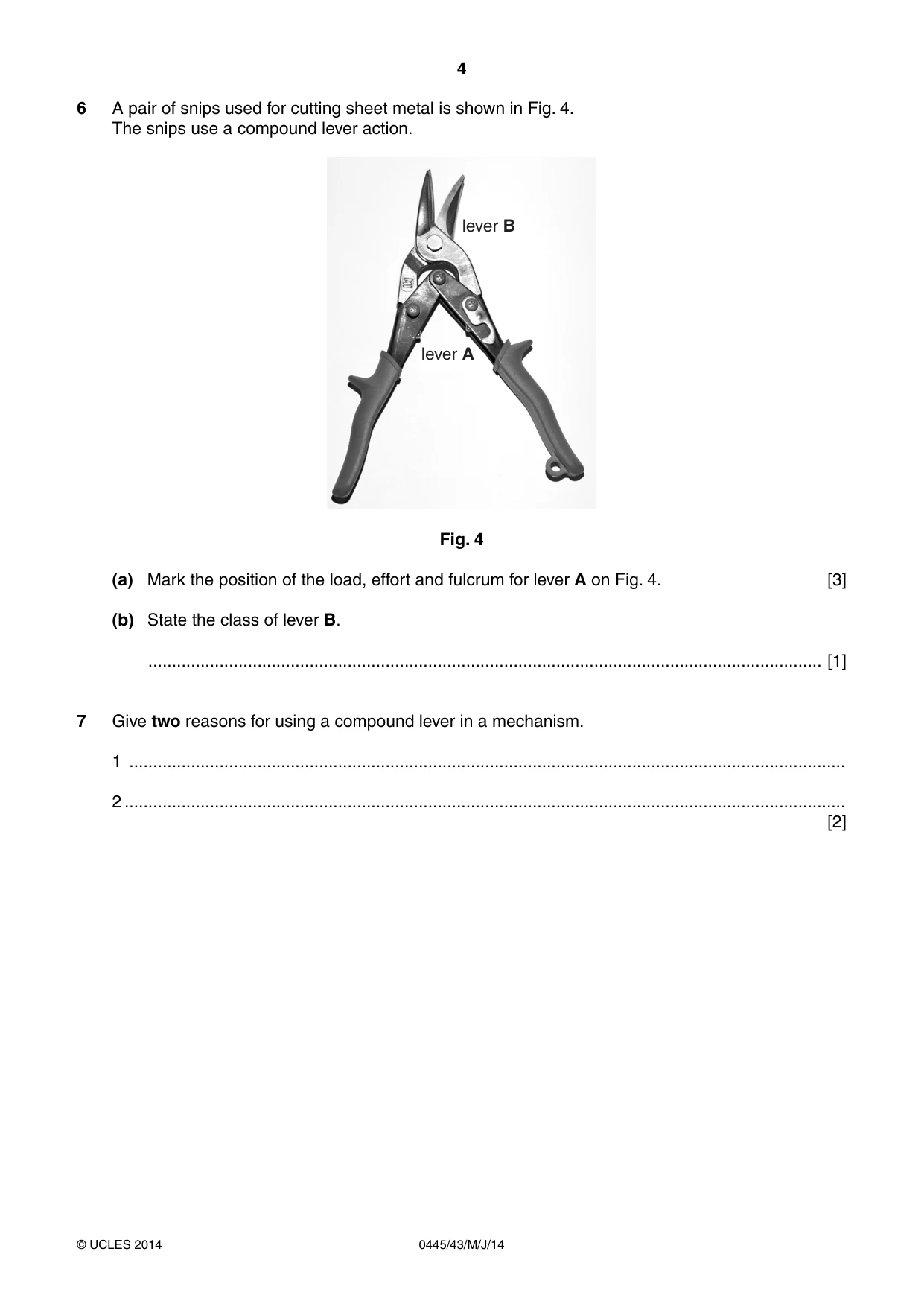
4 0445/43/M/J/14 © UCLES 2014 6 A pair of snips used for cutting sheet metal is shown in Fig. 4. The snips use a compound lever action. lever B lever A Fig. 4 (a) Mark the position of the load, effort and fulcrum for lever A on Fig. 4. [3] (b) State the class of lever B. … [1] 7 Give two reasons for using a compound lever in a mechanism. 1 … 2 … [2]
Question paper, page 5
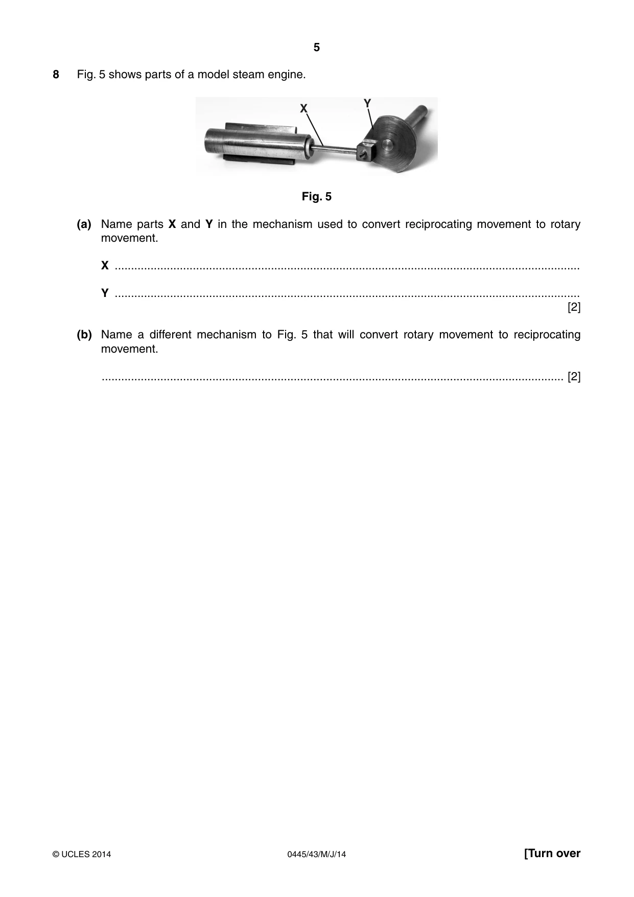
5 0445/43/M/J/14 © UCLES 2014 [Turn over 8 Fig. 5 shows parts of a model steam engine. X Y Fig. 5 (a) Name parts X and Y in the mechanism used to convert reciprocating movement to rotary movement. X … Y … [2] (b) Name a different mechanism to Fig. 5 that will convert rotary movement to reciprocating movement. … [2]
Question paper, page 6
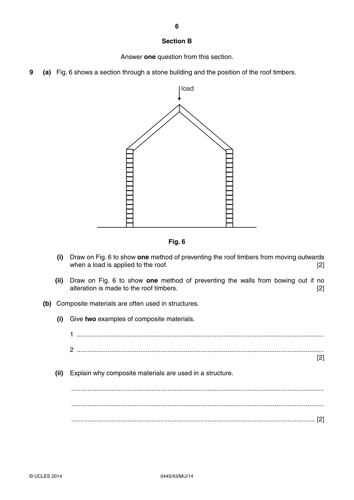
6 0445/43/M/J/14 © UCLES 2014 Section B Answer one question from this section. 9 (a) Fig. 6 shows a section through a stone building and the position of the roof timbers. load Fig. 6 (i) Draw on Fig. 6 to show one method of preventing the roof timbers from moving outwards when a load is applied to the roof. [2] (ii) Draw on Fig. 6 to show one method of preventing the walls from bowing out if no alteration is made to the roof timbers. [2] (b) Composite materials are often used in structures. (i) Give two examples of composite materials. 1 … 2 … [2] (ii) Explain why composite materials are used in a structure. … … … [2]
Question paper, page 7
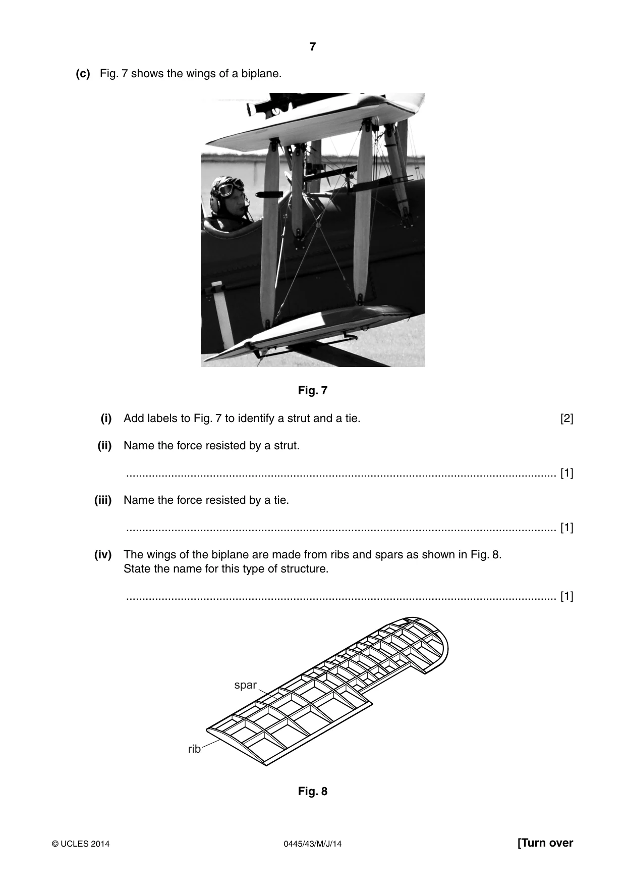
7 0445/43/M/J/14 © UCLES 2014 [Turn over (c) Fig. 7 shows the wings of a biplane. Fig. 7 (i) Add labels to Fig. 7 to identify a strut and a tie. [2] (ii) Name the force resisted by a strut. … [1] (iii) Name the force resisted by a tie. … [1] (iv) The wings of the biplane are made from ribs and spars as shown in Fig. 8. State the name for this type of structure. … [1] rib spar Fig. 8
Question paper, page 8
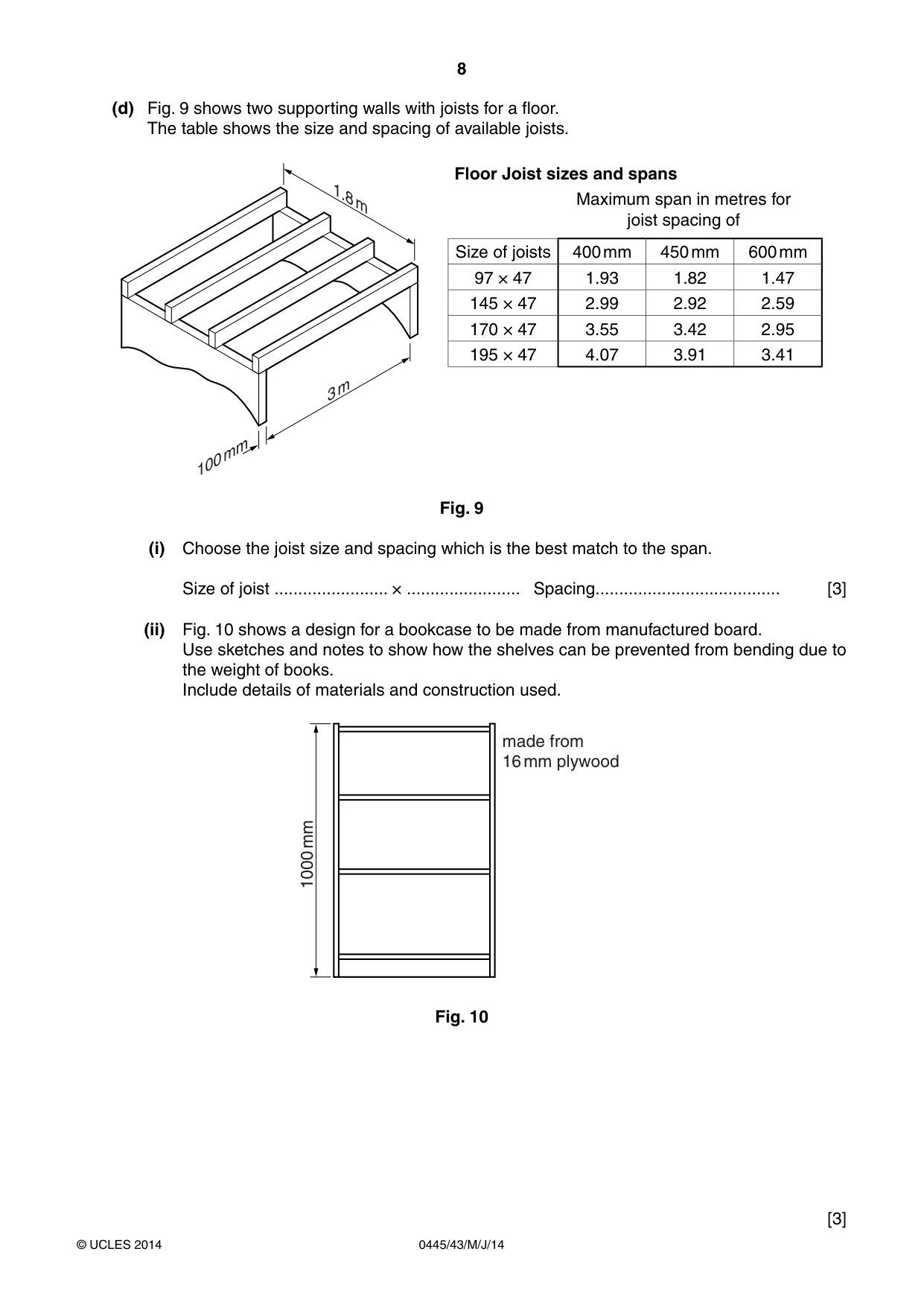
8 0445/43/M/J/14 © UCLES 2014 (d) Fig. 9 shows two supporting walls with joists for a floor. The table shows the size and spacing of available joists. 1.8 m 3 m 100 mm Floor Joist sizes and spans Maximum span in metres for joist spacing of Size of joists 400 mm 450 mm 600 mm 97 × 47 1.93 1.82 1.47 145 × 47 2.99 2.92 2.59 170 × 47 3.55 3.42 2.95 195 × 47 4.07 3.91 3.41 Fig. 9 (i) Choose the joist size and spacing which is the best match to the span. Size of joist … × … Spacing… [3] (ii) Fig. 10 shows a design for a bookcase to be made from manufactured board. Use sketches and notes to show how the shelves can be prevented from bending due to the weight of books. Include details of materials and construction used. 1000 mm made from 16 mm plywood Fig. 10 [3]
Question paper, page 9
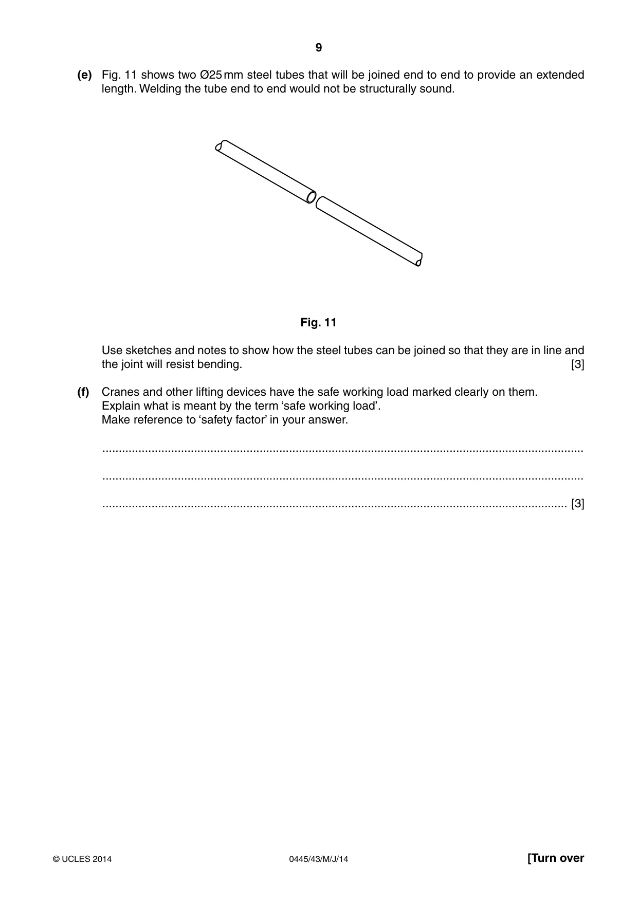
9 0445/43/M/J/14 © UCLES 2014 [Turn over (e) Fig. 11 shows two Ø25 mm steel tubes that will be joined end to end to provide an extended length. Welding the tube end to end would not be structurally sound. Fig. 11 Use sketches and notes to show how the steel tubes can be joined so that they are in line and the joint will resist bending. [3] (f) Cranes and other lifting devices have the safe working load marked clearly on them. Explain what is meant by the term ‘safe working load’. Make reference to ‘safety factor’ in your answer. … … … [3]
Question paper, page 10
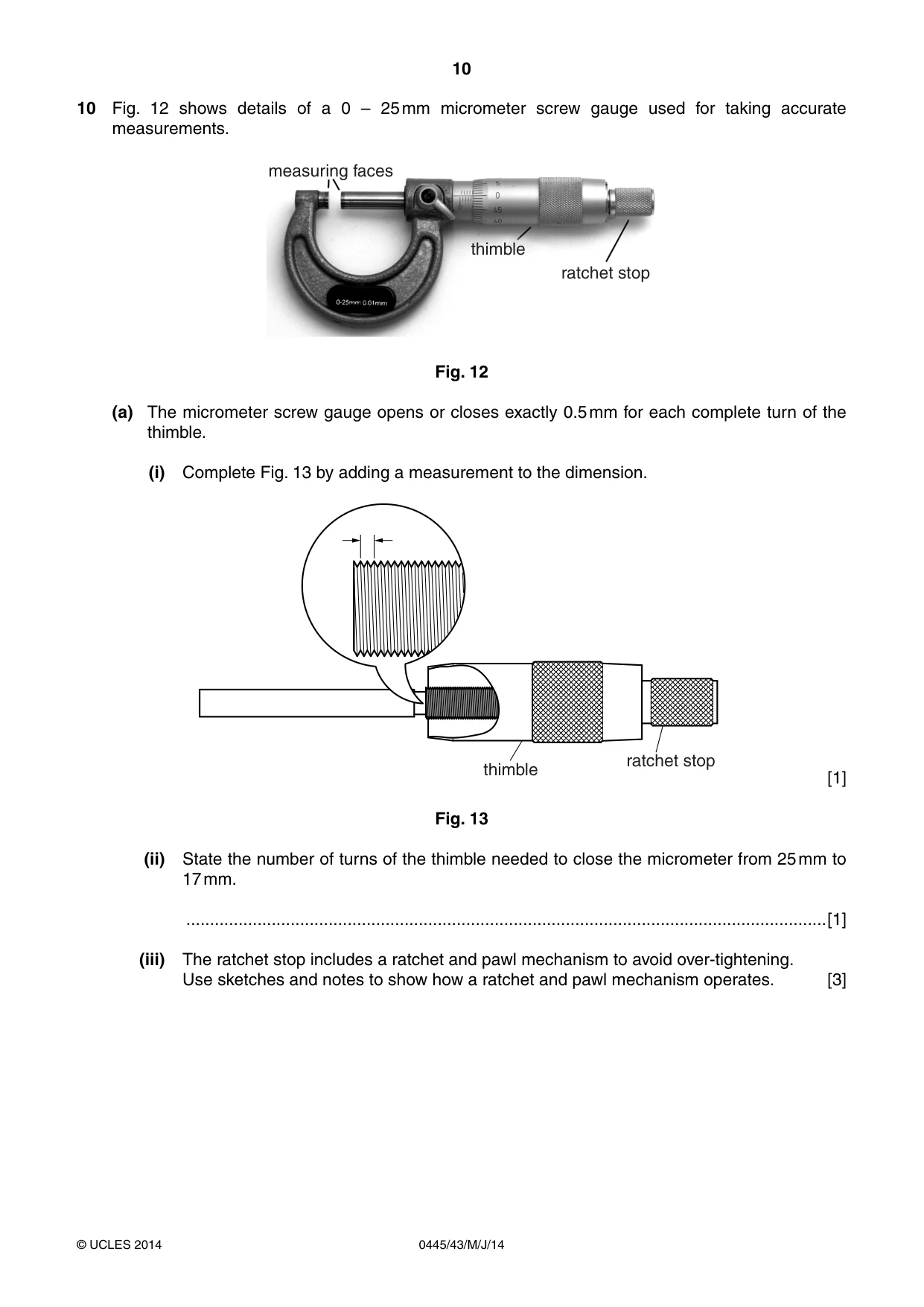
10 0445/43/M/J/14 © UCLES 2014 10 Fig. 12 shows details of a 0 – 25 mm micrometer screw gauge used for taking accurate measurements. ratchet stop thimble measuring faces Fig. 12 (a) The micrometer screw gauge opens or closes exactly 0.5 mm for each complete turn of the thimble. (i) Complete Fig. 13 by adding a measurement to the dimension. thimble ratchet stop [1] Fig. 13 (ii) State the number of turns of the thimble needed to close the micrometer from 25 mm to 17 mm. …[1] (iii) The ratchet stop includes a ratchet and pawl mechanism to avoid over-tightening. Use sketches and notes to show how a ratchet and pawl mechanism operates. [3]
Question paper, page 11
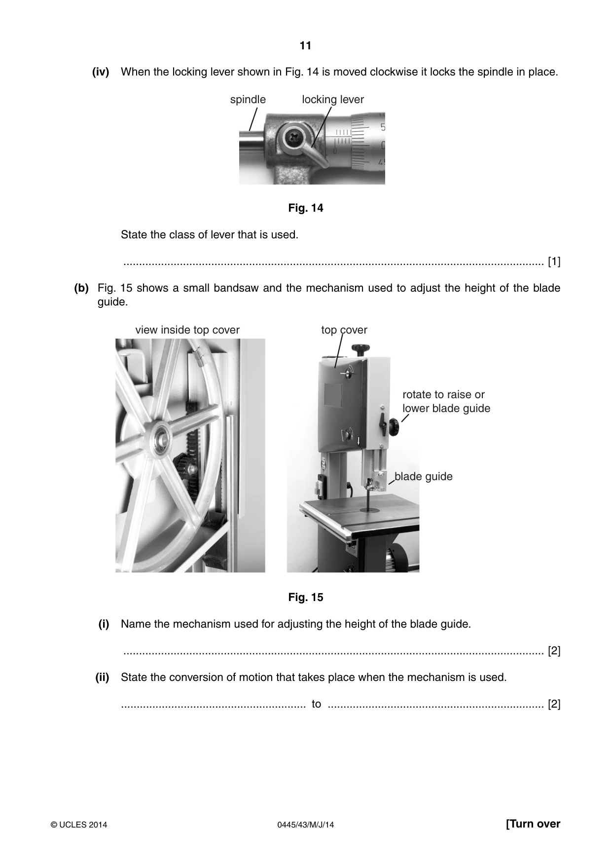
11 0445/43/M/J/14 © UCLES 2014 [Turn over (iv) When the locking lever shown in Fig. 14 is moved clockwise it locks the spindle in place. spindle locking lever Fig. 14 State the class of lever that is used. … [1] (b) Fig. 15 shows a small bandsaw and the mechanism used to adjust the height of the blade guide. view inside top cover top cover rotate to raise or lower blade guide blade guide Fig. 15 (i) Name the mechanism used for adjusting the height of the blade guide. … [2] (ii) State the conversion of motion that takes place when the mechanism is used. … to … … [2]
Question paper, page 12
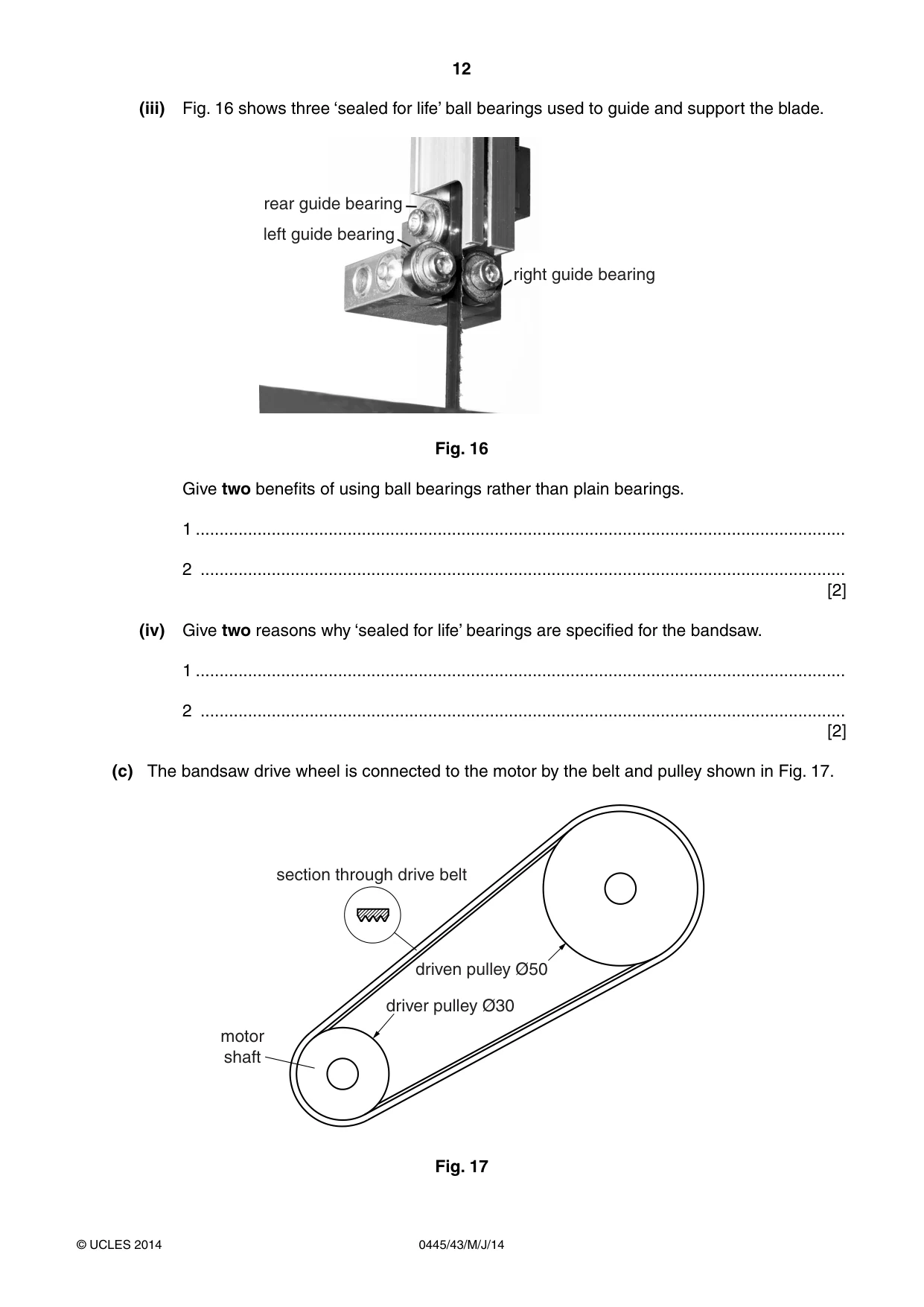
12 0445/43/M/J/14 © UCLES 2014 (iii) Fig. 16 shows three ‘sealed for life’ ball bearings used to guide and support the blade. right guide bearing rear guide bearing left guide bearing Fig. 16 Give two benefits of using ball bearings rather than plain bearings. 1 … 2 … [2] (iv) Give two reasons why ‘sealed for life’ bearings are specified for the bandsaw. 1 … 2 … [2] (c) The bandsaw drive wheel is connected to the motor by the belt and pulley shown in Fig. 17. driver pulley Ø30 driven pulley Ø50 section through drive belt motor shaft Fig. 17
Question paper, page 13
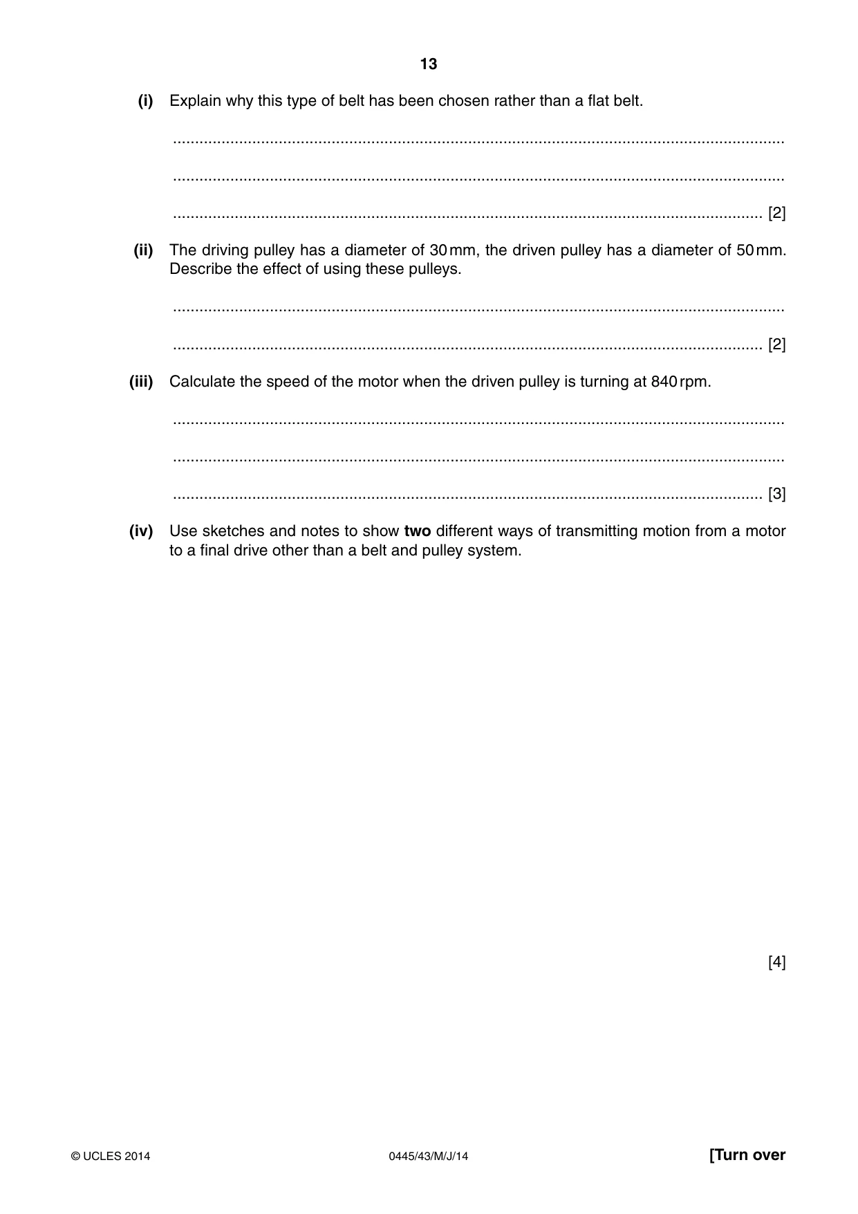
13 0445/43/M/J/14 © UCLES 2014 [Turn over (i) Explain why this type of belt has been chosen rather than a flat belt. … … … [2] (ii) The driving pulley has a diameter of 30 mm, the driven pulley has a diameter of 50 mm. Describe the effect of using these pulleys. … … [2] (iii) Calculate the speed of the motor when the driven pulley is turning at 840 rpm. … … … [3] (iv) Use sketches and notes to show two different ways of transmitting motion from a motor to a final drive other than a belt and pulley system. [4]
Question paper, page 14
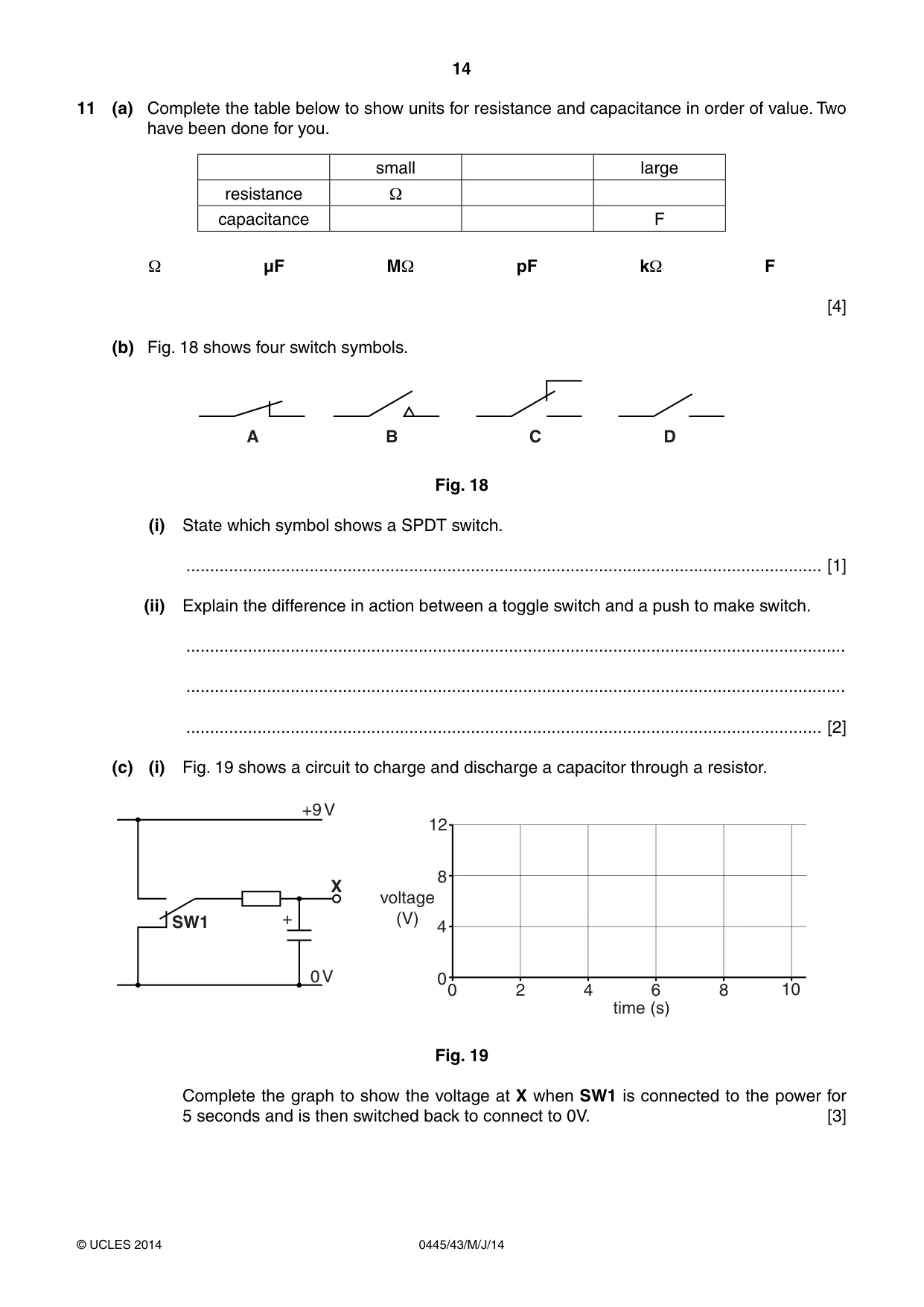
14 0445/43/M/J/14 © UCLES 2014 11 (a) Complete the table below to show units for resistance and capacitance in order of value. Two have been done for you. small large resistance Ω capacitance F Ω µF MΩ pF kΩ F [4] (b) Fig. 18 shows four switch symbols. A B C D Fig. 18 (i) State which symbol shows a SPDT switch. … [1] (ii) Explain the difference in action between a toggle switch and a push to make switch. … … … [2] (c) (i) Fig. 19 shows a circuit to charge and discharge a capacitor through a resistor. X +9 V 0 V + SW1 voltage (V) 0 8 4 12 time (s) 0 2 4 6 8 10 Fig. 19 Complete the graph to show the voltage at X when SW1 is connected to the power for 5 seconds and is then switched back to connect to 0V. [3]
Question paper, page 15
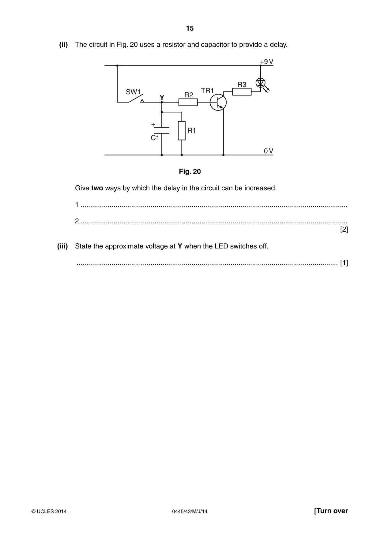
15 0445/43/M/J/14 © UCLES 2014 [Turn over (ii) The circuit in Fig. 20 uses a resistor and capacitor to provide a delay. +9 V 0 V SW1 Y R1 R2 R3 TR1 C1 + Fig. 20 Give two ways by which the delay in the circuit can be increased. 1 … 2 … [2] (iii) State the approximate voltage at Y when the LED switches off. … [1]
Question paper, page 16
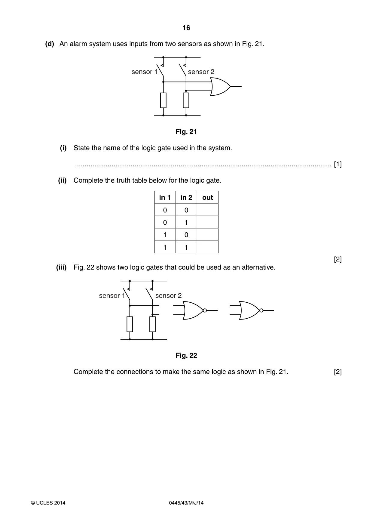
16 0445/43/M/J/14 © UCLES 2014 (d) An alarm system uses inputs from two sensors as shown in Fig. 21. sensor 1 sensor 2 Fig. 21 (i) State the name of the logic gate used in the system. … [1] (ii) Complete the truth table below for the logic gate. in 1 in 2 out 0 0 0 1 1 0 1 1 [2] (iii) Fig. 22 shows two logic gates that could be used as an alternative. sensor 1 sensor 2 Fig. 22 Complete the connections to make the same logic as shown in Fig. 21. [2]
Question paper, page 17
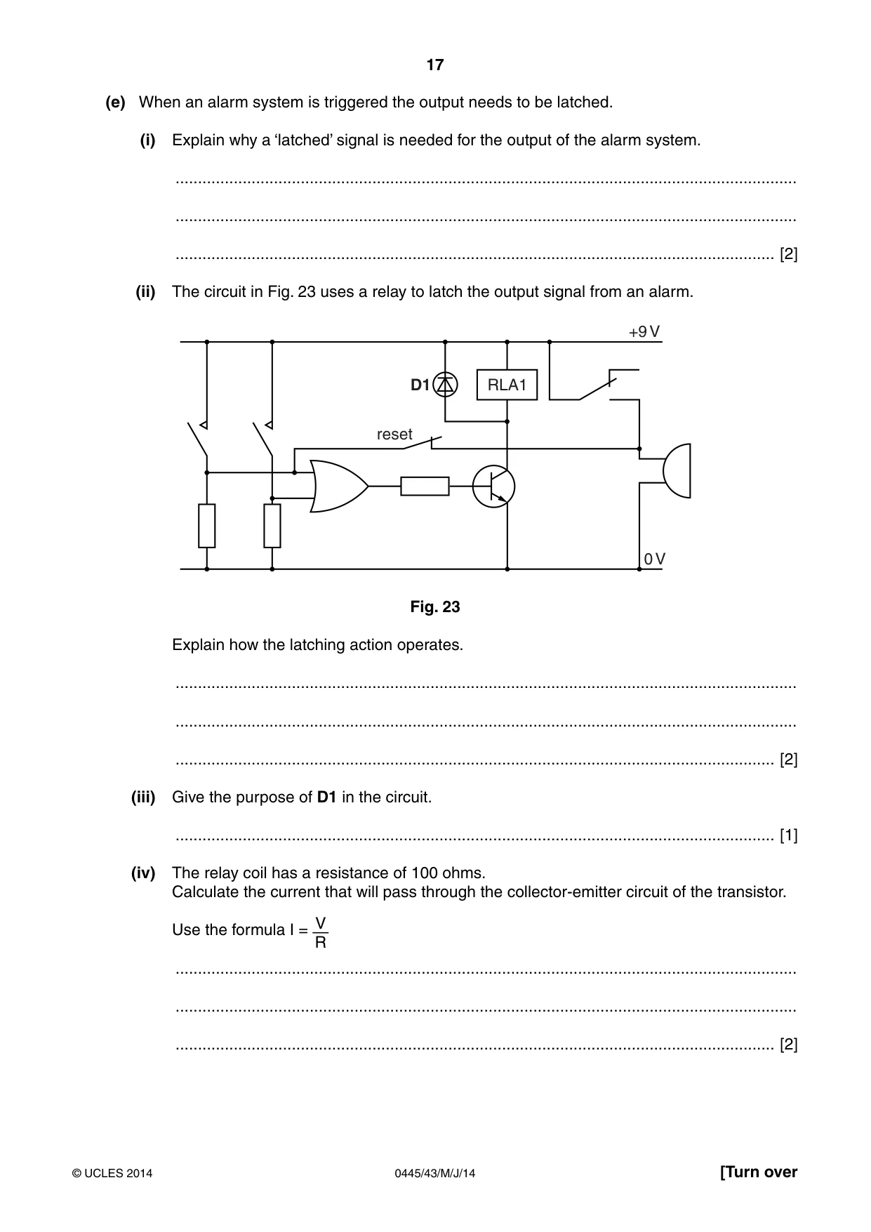
17 0445/43/M/J/14 © UCLES 2014 [Turn over (e) When an alarm system is triggered the output needs to be latched. (i) Explain why a ‘latched’ signal is needed for the output of the alarm system. … … … [2] (ii) The circuit in Fig. 23 uses a relay to latch the output signal from an alarm. +9 V 0 V RLA1 D1 reset Fig. 23 Explain how the latching action operates. … … … [2] (iii) Give the purpose of D1 in the circuit. … [1] (iv) The relay coil has a resistance of 100 ohms. Calculate the current that will pass through the collector-emitter circuit of the transistor. Use the formula I = V R … … … [2]
Question paper, page 18
18 0445/43/M/J/14 © UCLES 2014 BLANK PAGE
Question paper, page 19
19 0445/43/M/J/14 © UCLES 2014 BLANK PAGE
Question paper, page 20
20 0445/43/M/J/14 © UCLES 2014 Permission to reproduce items where third-party owned material protected by copyright is included has been sought and cleared where possible. Every reasonable effort has been made by the publisher (UCLES) to trace copyright holders, but if any items requiring clearance have unwittingly been included, the publisher will be pleased to make amends at the earliest possible opportunity. Cambridge International Examinations is part of the Cambridge Assessment Group. Cambridge Assessment is the brand name of University of Cambridge Local Examinations Syndicate (UCLES), which is itself a department of the University of Cambridge. BLANK PAGE
What you needed in this session
Cambridge’s own grade thresholds for 2014 May/June, Paper 4 · Variant 3. A higher threshold means an easier paper — the bar moves with how the cohort did.