Cambridge IGCSE Design and Technology 0445 — 2013 Oct/Nov Paper 4 · Variant 1
0445/41/O/N/13 · 50 marks · ≈56 min
The question paper and its mark scheme, free to read here and free to download. This is Cambridge’s own paper, exactly as it was sat.
Question paper20 pages

Mark scheme8 pages
Answers below. Sit the paper first if you are practising.
Paper as text
Question paper, page 1
[Turn over *0080054038* READ THESE INSTRUCTIONS FIRST Write your Centre number, candidate number and name on all the work you hand in. Write in dark blue or black pen. You may use a soft pencil for any diagrams, graphs or rough working. Do not use staples, paper clips, highlighters, glue or correction fl uid. DO NOT WRITE IN ANY BARCODES. You may use a calculator. Section A Answer all questions. Section B Answer one question. The total of the marks for this paper is 50. The number of marks is given in brackets [ ] at the end of each question or part question. For Examiner’s Use Section A Section B Total DESIGN AND TECHNOLOGY 0445/41 Paper 4 Systems and Control October/November 2013 1 hour Candidates answer on the Question Paper. No Additional Materials are required. To be taken together with Paper 1 in one session of 2 hours and 15 minutes. UNIVERSITY OF CAMBRIDGE INTERNATIONAL EXAMINATIONS International General Certifi cate of Secondary Education This document consists of an 18 printed pages and 2 blank pages. [Turn over IB13 11_0445_41/3RP © UCLES 2013
Question paper, page 2
2 0445/41/O/N/13 © UCLES 2013 For Examiner’s Use Section A Answer all questions in this section. 1 Fig. 1 shows the support frame for a shelf unit attached to a wall using screws. Fig. 1 (a) State the force that was acting on each screw as it was inserted with a screwdriver. … [1] (b) State the force that will act on the screws when a load is applied in the direction of the arrows. … [1] (c) Describe how the factor of safety on the fi xing of the support frame to the wall could be increased. … … … [2] 2 Give one example of a natural shell structure and one example of a manufactured shell structure. Natural shell structure … [1] Manufactured shell structure … [1]
Question paper, page 3
3 0445/41/O/N/13 © UCLES 2013 [Turn over For Examiner’s Use 3 Draw and name an example of a third-order lever. [2] 4 Use notes and sketches to show how the piece of card in Fig. 2 can be modifi ed to be self-supporting and allow the card to support a compressive load. No additional materials should be used. card table top Fig. 2 [2]
Question paper, page 4
4 0445/41/O/N/13 © UCLES 2013 For Examiner’s Use 5 Fig. 3 shows shear legs being used to raise a load. Add labels to show: ● a structural component in tension; ● a structural component in compression. Fig. 3 [2] 6 Fig. 4 shows a gear system. Fig. 4 B A 48 teeth (a) Name the two components in the gear system. A … B … [2] (b) State the reduction ratio of the gear system in Fig. 4. … [1]
Question paper, page 5
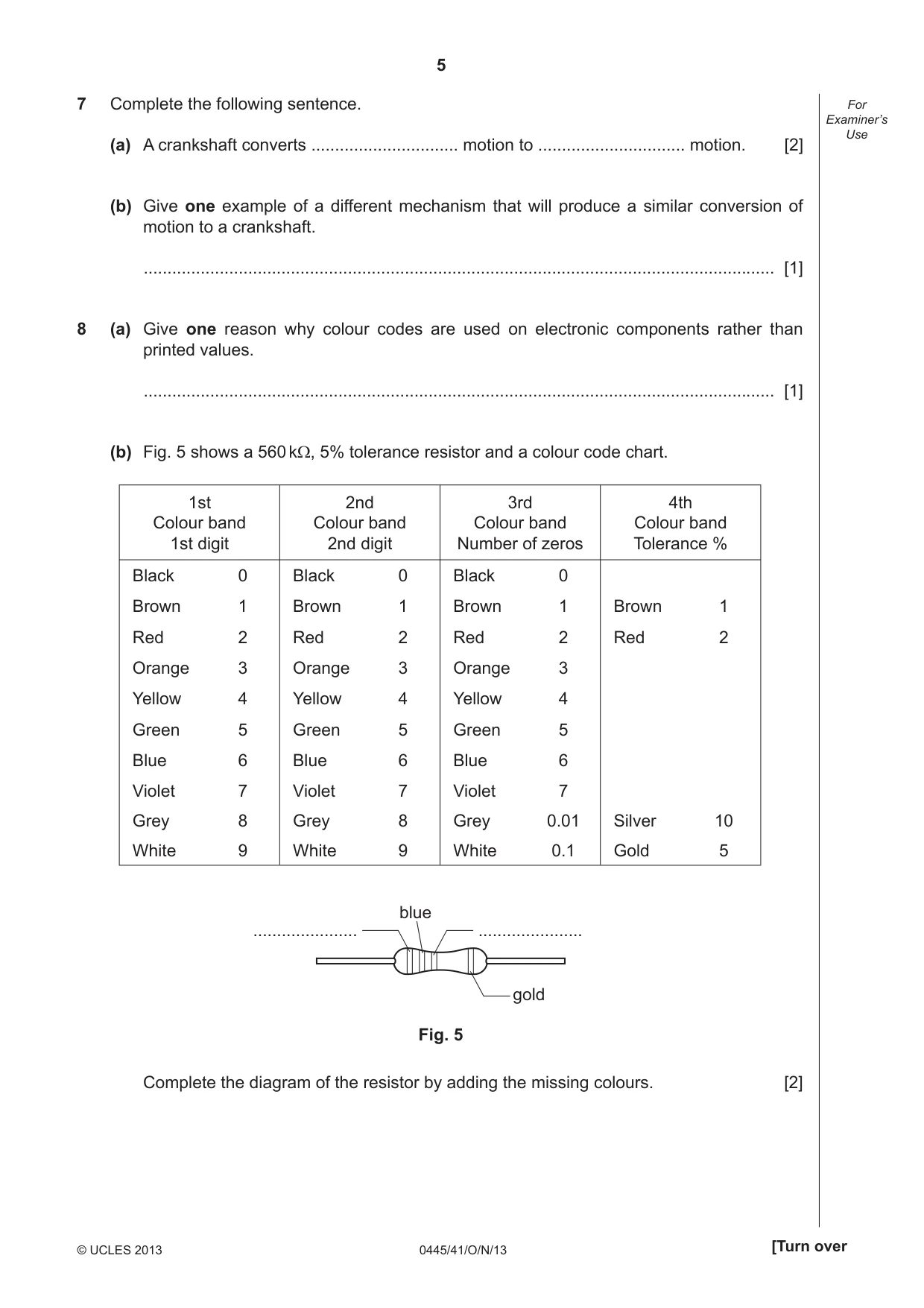
5 0445/41/O/N/13 © UCLES 2013 [Turn over For Examiner’s Use 7 Complete the following sentence. (a) A crankshaft converts … motion to … motion. [2] (b) Give one example of a different mechanism that will produce a similar conversion of motion to a crankshaft. … [1] 8 (a) Give one reason why colour codes are used on electronic components rather than printed values. … [1] (b) Fig. 5 shows a 560 kΩ, 5% tolerance resistor and a colour code chart. 1st Colour band 1st digit 2nd Colour band 2nd digit 3rd Colour band Number of zeros 4th Colour band Tolerance % Black 0 Black 0 Black 0 Brown 1 Brown 1 Brown 1 Brown 1 Red 2 Red 2 Red 2 Red 2 Orange 3 Orange 3 Orange 3 Yellow 4 Yellow 4 Yellow 4 Green 5 Green 5 Green 5 Blue 6 Blue 6 Blue 6 Violet 7 Violet 7 Violet 7 Grey 8 Grey 8 Grey 0.01 Silver 10 White 9 White 9 White 0.1 Gold 5 … … gold blue Fig. 5 Complete the diagram of the resistor by adding the missing colours. [2]
Question paper, page 6
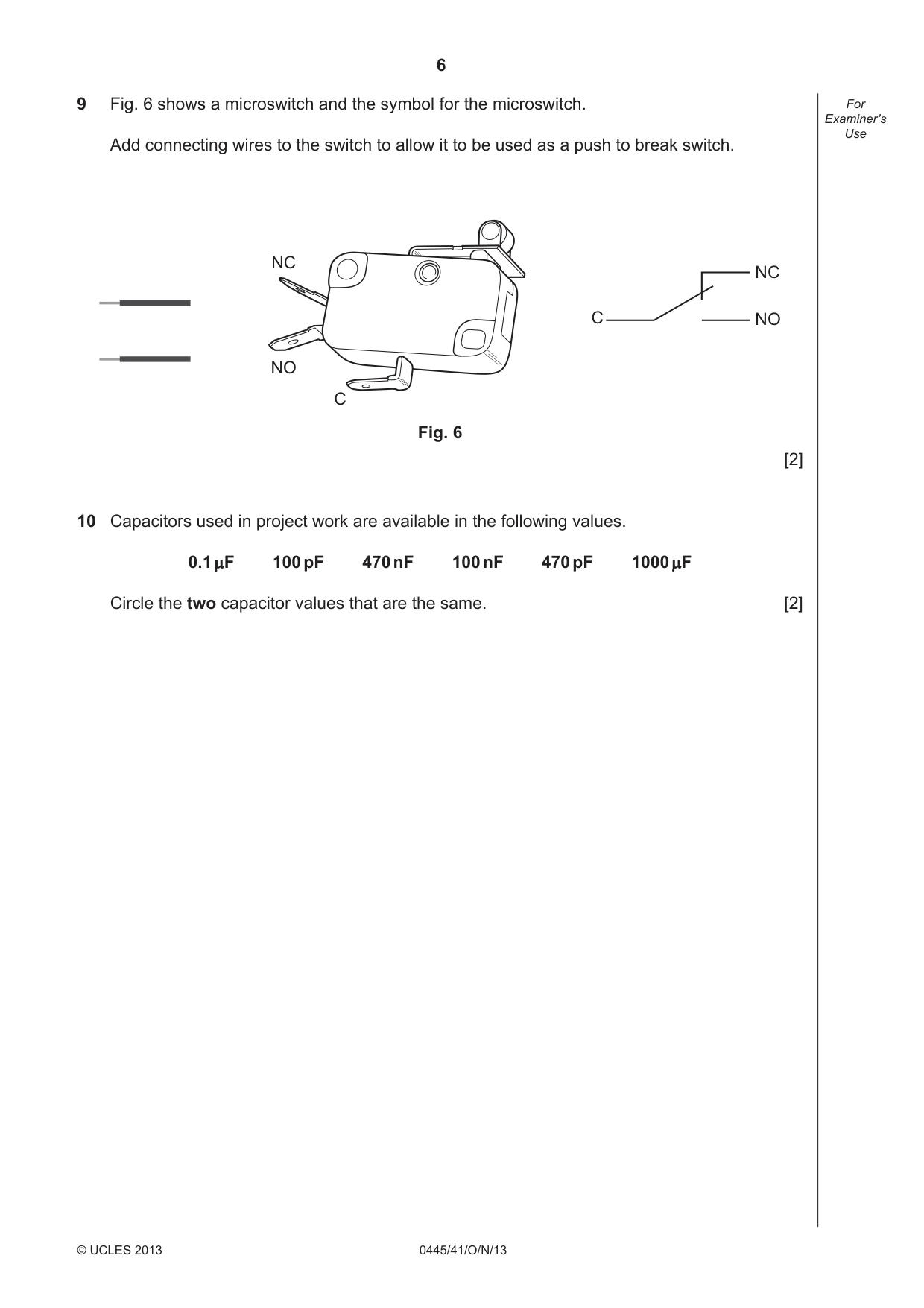
6 0445/41/O/N/13 © UCLES 2013 For Examiner’s Use 9 Fig. 6 shows a microswitch and the symbol for the microswitch. Add connecting wires to the switch to allow it to be used as a push to break switch. C NC NO NC NO C Fig. 6 [2] 10 Capacitors used in project work are available in the following values. 0.1 µF 100 pF 470 nF 100 nF 470 pF 1000 µF Circle the two capacitor values that are the same. [2]
Question paper, page 7
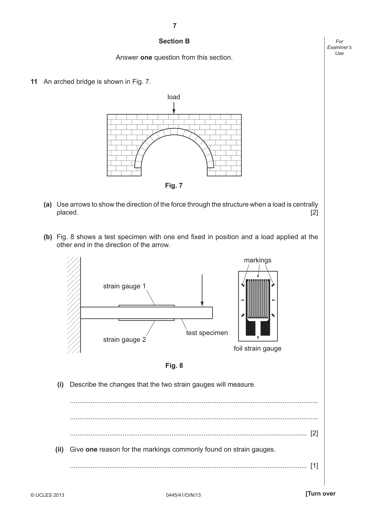
7 0445/41/O/N/13 © UCLES 2013 [Turn over For Examiner’s Use Section B Answer one question from this section. 11 An arched bridge is shown in Fig. 7. load Fig. 7 (a) Use arrows to show the direction of the force through the structure when a load is centrally placed. [2] (b) Fig. 8 shows a test specimen with one end fi xed in position and a load applied at the other end in the direction of the arrow. strain gauge 1 test specimen strain gauge 2 markings foil strain gauge Fig. 8 (i) Describe the changes that the two strain gauges will measure. … … … [2] (ii) Give one reason for the markings commonly found on strain gauges. … [1]
Question paper, page 8
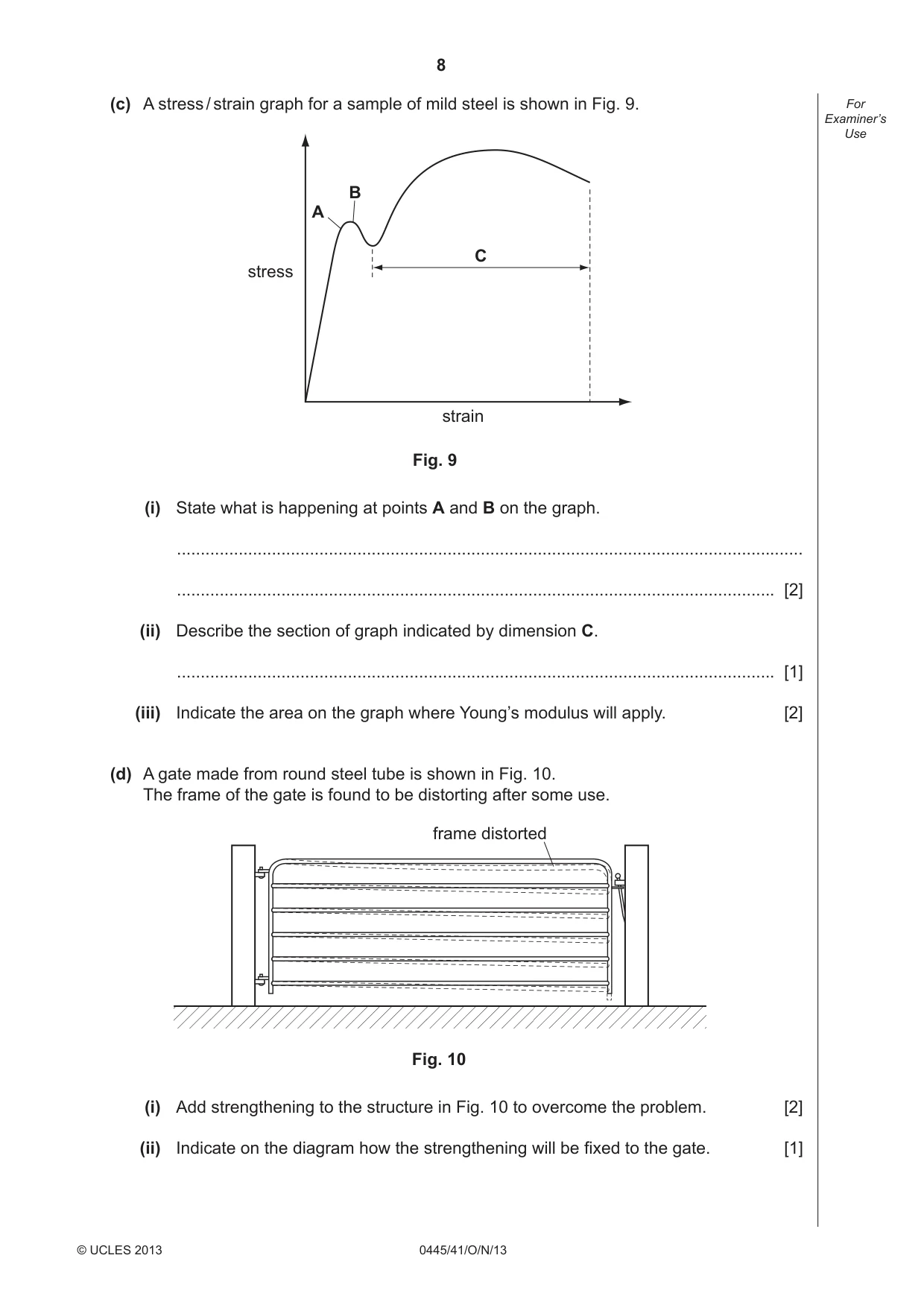
8 0445/41/O/N/13 © UCLES 2013 For Examiner’s Use (c) A stress / strain graph for a sample of mild steel is shown in Fig. 9. stress strain Fig. 9 C A B (i) State what is happening at points A and B on the graph. … … [2] (ii) Describe the section of graph indicated by dimension C. … [1] (iii) Indicate the area on the graph where Young’s modulus will apply. [2] (d) A gate made from round steel tube is shown in Fig. 10. The frame of the gate is found to be distorting after some use. frame distorted Fig. 10 (i) Add strengthening to the structure in Fig. 10 to overcome the problem. [2] (ii) Indicate on the diagram how the strengthening will be fi xed to the gate. [1]
Question paper, page 9
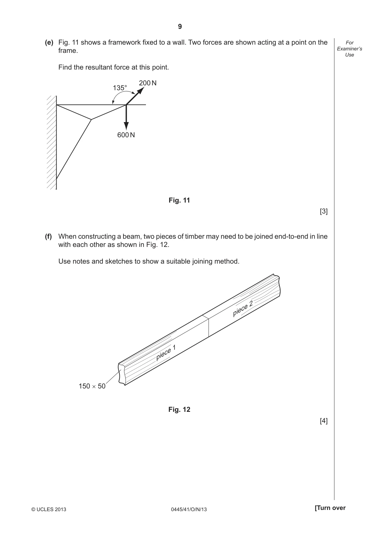
9 0445/41/O/N/13 © UCLES 2013 [Turn over For Examiner’s Use (e) Fig. 11 shows a framework fi xed to a wall. Two forces are shown acting at a point on the frame. Find the resultant force at this point. 600 N 200 N 135° Fig. 11 [3] (f) When constructing a beam, two pieces of timber may need to be joined end-to-end in line with each other as shown in Fig. 12. Use notes and sketches to show a suitable joining method. 150 × 50 piece 1 piece 2 Fig. 12 [4]
Question paper, page 10
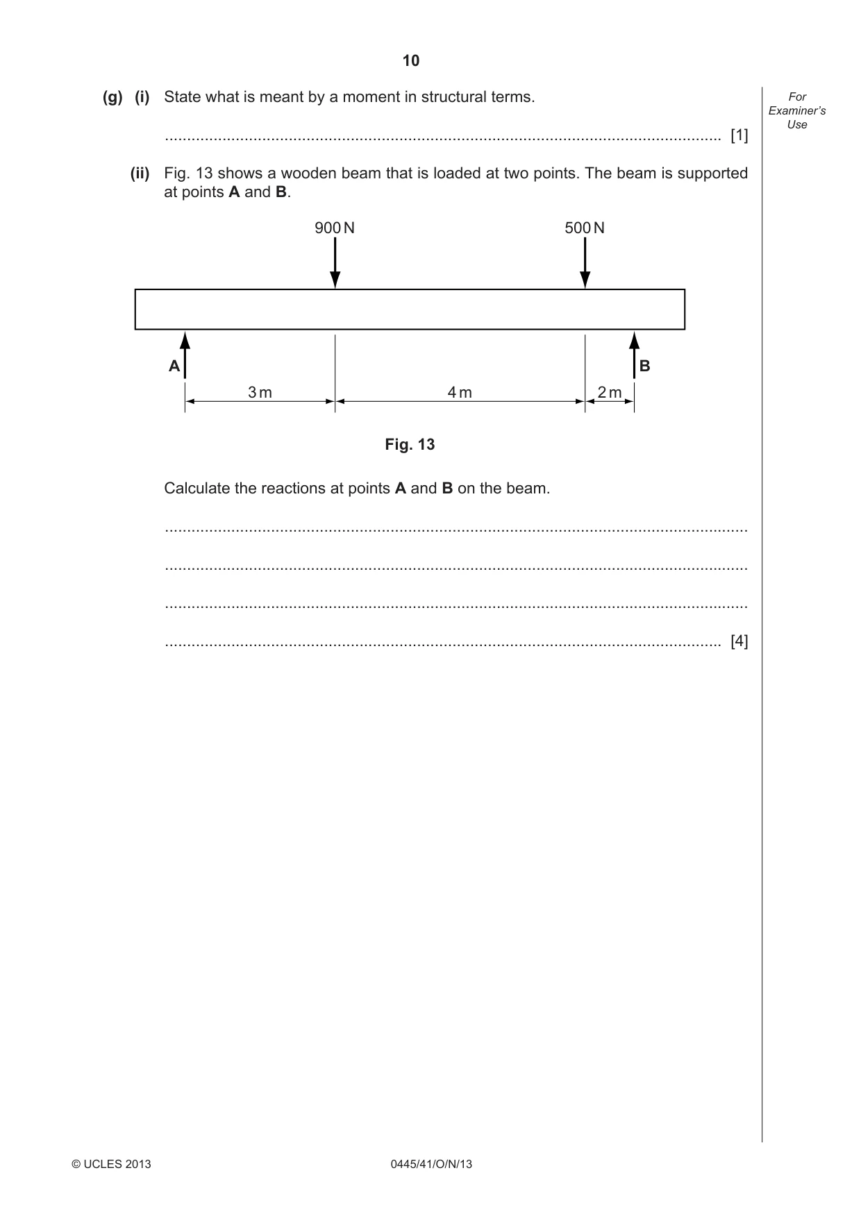
10 0445/41/O/N/13 © UCLES 2013 For Examiner’s Use (g) (i) State what is meant by a moment in structural terms. … [1] (ii) Fig. 13 shows a wooden beam that is loaded at two points. The beam is supported at points A and B. A B 900 N 500 N 3 m 2 m 4 m Fig. 13 Calculate the reactions at points A and B on the beam. … … … … [4]
Question paper, page 11
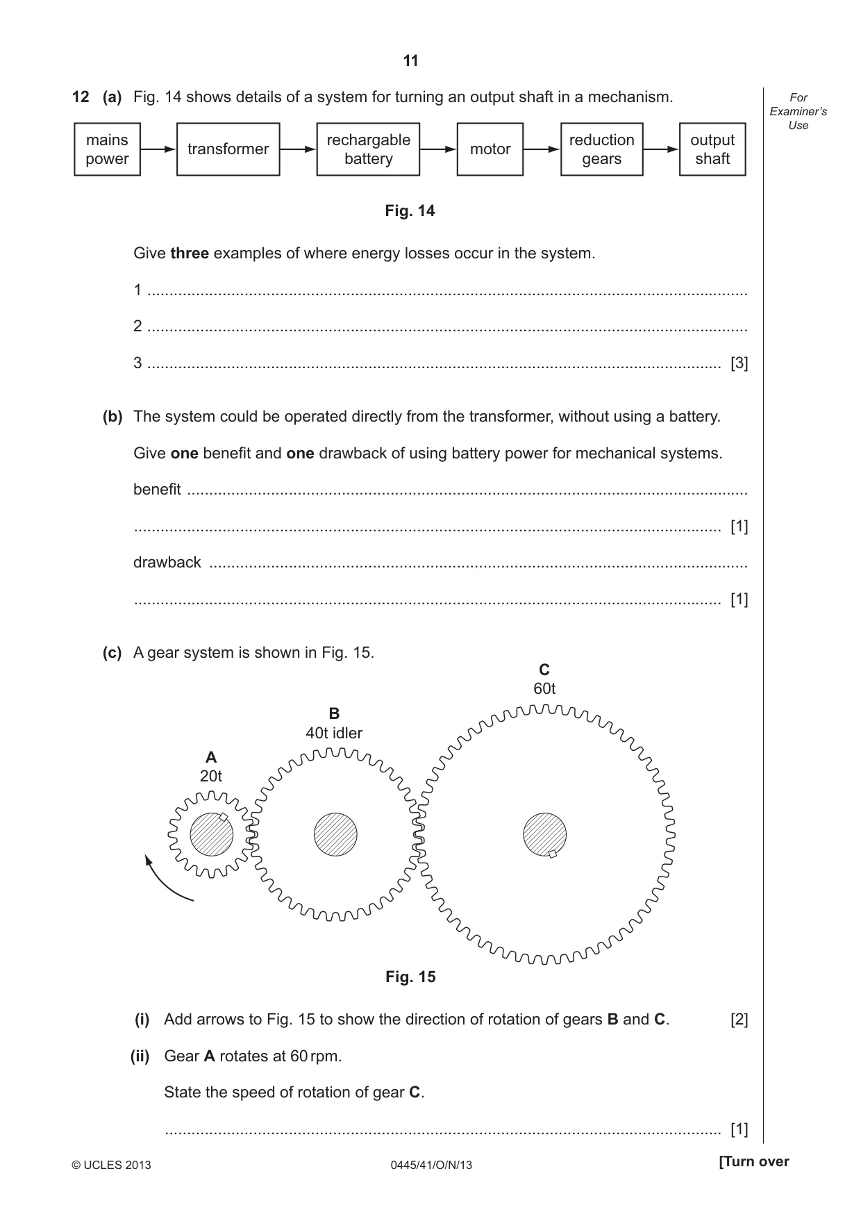
11 0445/41/O/N/13 © UCLES 2013 [Turn over For Examiner’s Use 12 (a) Fig. 14 shows details of a system for turning an output shaft in a mechanism. mains power rechargable battery reduction gears output shaft transformer motor Fig. 14 Give three examples of where energy losses occur in the system. 1 … 2 … 3 … [3] (b) The system could be operated directly from the transformer, without using a battery. Give one benefi t and one drawback of using battery power for mechanical systems. benefi t … … [1] drawback … … [1] (c) A gear system is shown in Fig. 15. A 20t C 60t B 40t idler Fig. 15 (i) Add arrows to Fig. 15 to show the direction of rotation of gears B and C. [2] (ii) Gear A rotates at 60 rpm. State the speed of rotation of gear C. … [1]
Question paper, page 12
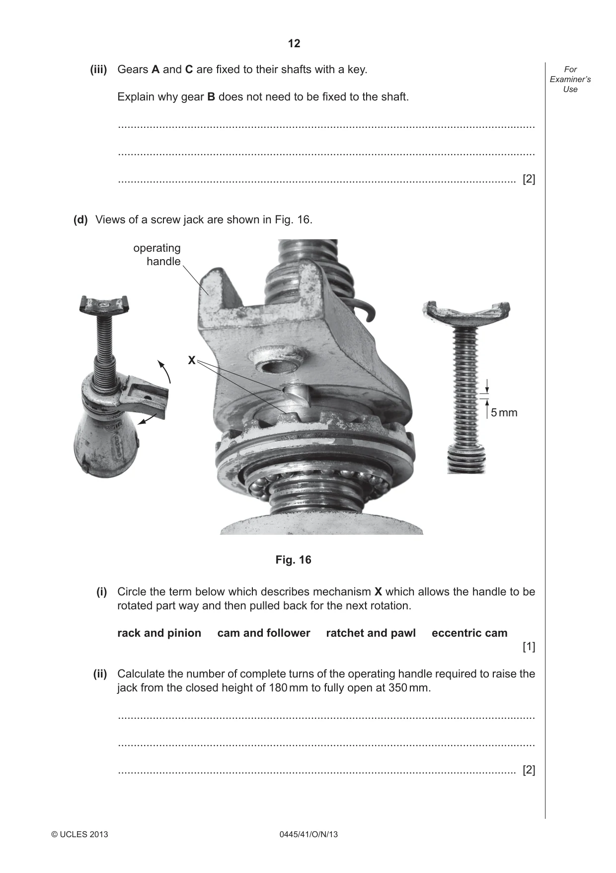
12 0445/41/O/N/13 © UCLES 2013 For Examiner’s Use (iii) Gears A and C are fi xed to their shafts with a key. Explain why gear B does not need to be fi xed to the shaft. … … … [2] (d) Views of a screw jack are shown in Fig. 16. operating handle X 5 mm Fig. 16 (i) Circle the term below which describes mechanism X which allows the handle to be rotated part way and then pulled back for the next rotation. rack and pinion cam and follower ratchet and pawl eccentric cam [1] (ii) Calculate the number of complete turns of the operating handle required to raise the jack from the closed height of 180 mm to fully open at 350 mm. … … … [2]
Question paper, page 13
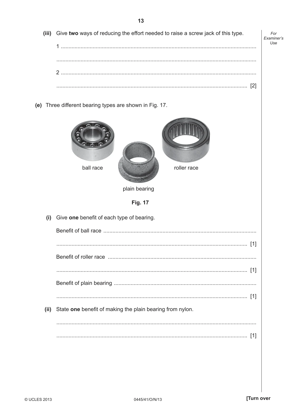
13 0445/41/O/N/13 © UCLES 2013 [Turn over For Examiner’s Use (iii) Give two ways of reducing the effort needed to raise a screw jack of this type. 1 … … 2 … … [2] (e) Three different bearing types are shown in Fig. 17. plain bearing ball race roller race Fig. 17 (i) Give one benefi t of each type of bearing. Benefi t of ball race … … [1] Benefi t of roller race … … [1] Benefi t of plain bearing … … [1] (ii) State one benefi t of making the plain bearing from nylon. … … [1]
Question paper, page 14
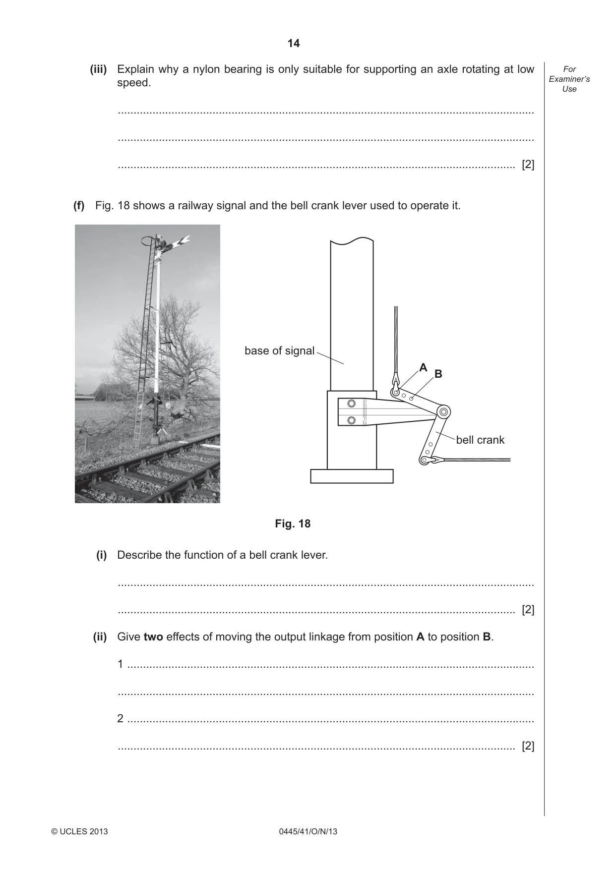
14 0445/41/O/N/13 © UCLES 2013 For Examiner’s Use (iii) Explain why a nylon bearing is only suitable for supporting an axle rotating at low speed. … … … [2] (f) Fig. 18 shows a railway signal and the bell crank lever used to operate it. bell crank A B base of signal Fig. 18 (i) Describe the function of a bell crank lever. … … [2] (ii) Give two effects of moving the output linkage from position A to position B. 1 … … 2 … … [2]
Question paper, page 15
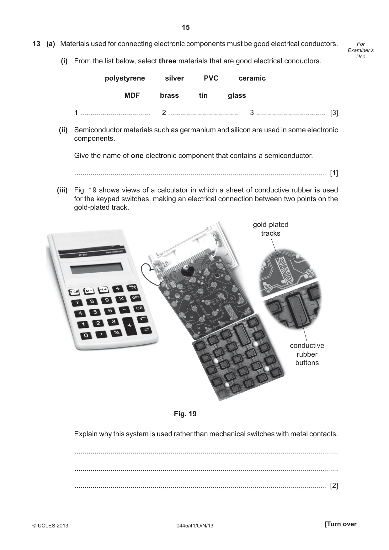
15 0445/41/O/N/13 © UCLES 2013 [Turn over For Examiner’s Use 13 (a) Materials used for connecting electronic components must be good electrical conductors. (i) From the list below, select three materials that are good electrical conductors. polystyrene silver PVC ceramic MDF brass tin glass 1 … 2 … 3 … [3] (ii) Semiconductor materials such as germanium and silicon are used in some electronic components. Give the name of one electronic component that contains a semiconductor. … [1] (iii) Fig. 19 shows views of a calculator in which a sheet of conductive rubber is used for the keypad switches, making an electrical connection between two points on the gold-plated track. Fig. 19 conductive rubber buttons gold-plated tracks Explain why this system is used rather than mechanical switches with metal contacts. … … … [2]
Question paper, page 16
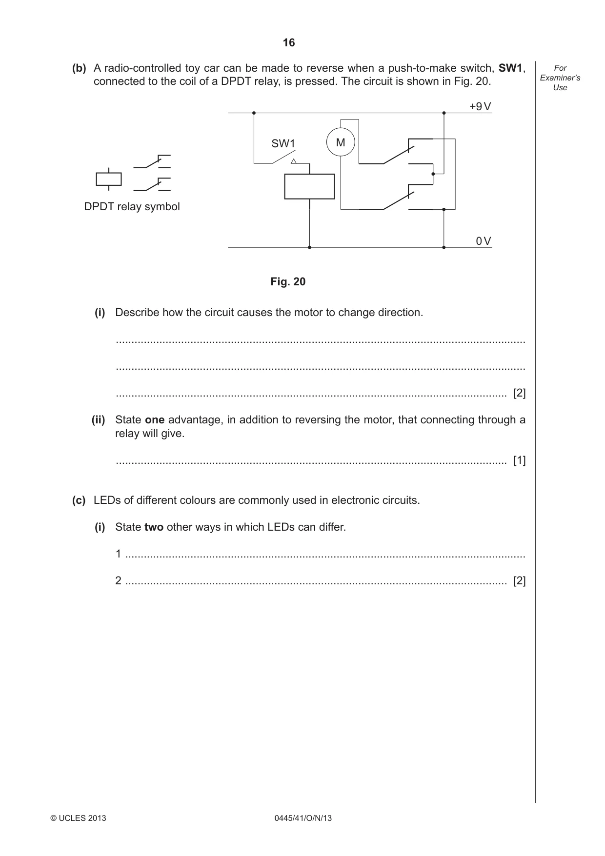
16 0445/41/O/N/13 © UCLES 2013 For Examiner’s Use (b) A radio-controlled toy car can be made to reverse when a push-to-make switch, SW1, connected to the coil of a DPDT relay, is pressed. The circuit is shown in Fig. 20. DPDT relay symbol M +9 V 0 V SW1 Fig. 20 (i) Describe how the circuit causes the motor to change direction. … … … [2] (ii) State one advantage, in addition to reversing the motor, that connecting through a relay will give. … [1] (c) LEDs of different colours are commonly used in electronic circuits. (i) State two other ways in which LEDs can differ. 1 … 2 … [2]
Question paper, page 17
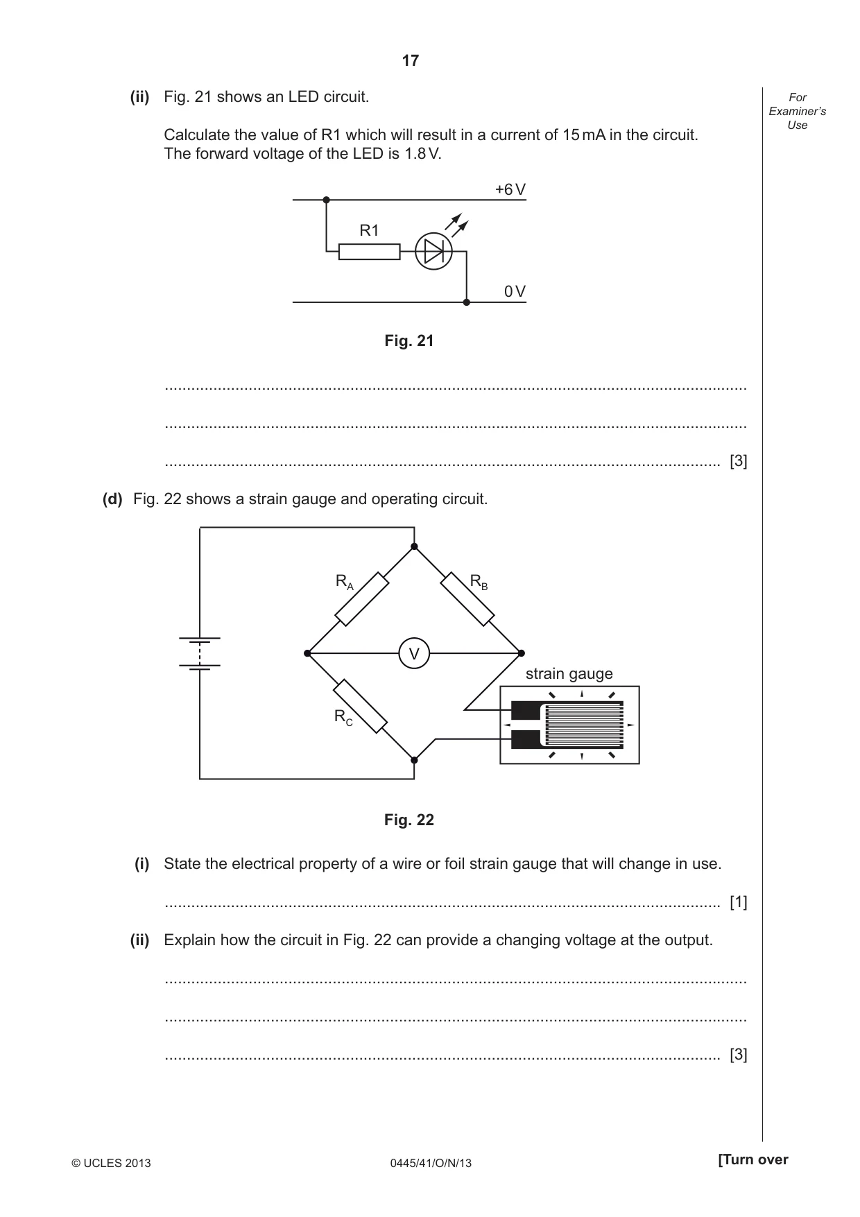
17 0445/41/O/N/13 © UCLES 2013 [Turn over For Examiner’s Use (ii) Fig. 21 shows an LED circuit. Calculate the value of R1 which will result in a current of 15 mA in the circuit. The forward voltage of the LED is 1.8 V. R1 +6 V 0 V Fig. 21 … … … [3] (d) Fig. 22 shows a strain gauge and operating circuit. RA RB RC V strain gauge Fig. 22 (i) State the electrical property of a wire or foil strain gauge that will change in use. … [1] (ii) Explain how the circuit in Fig. 22 can provide a changing voltage at the output. … … … [3]
Question paper, page 18
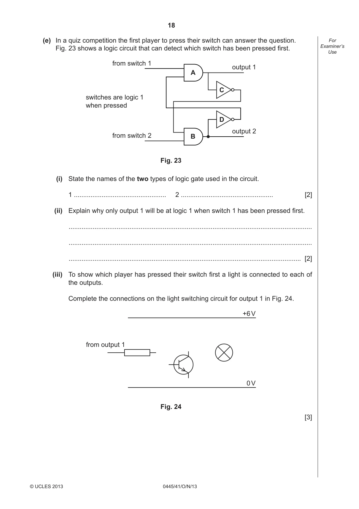
18 0445/41/O/N/13 © UCLES 2013 For Examiner’s Use (e) In a quiz competition the fi rst player to press their switch can answer the question. Fig. 23 shows a logic circuit that can detect which switch has been pressed fi rst. A B D C output 1 output 2 from switch 1 from switch 2 switches are logic 1 when pressed Fig. 23 (i) State the names of the two types of logic gate used in the circuit. 1 … 2 … [2] (ii) Explain why only output 1 will be at logic 1 when switch 1 has been pressed fi rst. … … … [2] (iii) To show which player has pressed their switch fi rst a light is connected to each of the outputs. Complete the connections on the light switching circuit for output 1 in Fig. 24. +6 V 0 V from output 1 Fig. 24 [3]
Question paper, page 19
19 0445/41/O/N/13 BLANK PAGE © UCLES 2013
Question paper, page 20
20 0445/41/O/N/13 Permission to reproduce items where third-party owned material protected by copyright is included has been sought and cleared where possible. Every reasonable effort has been made by the publisher (UCLES) to trace copyright holders, but if any items requiring clearance have unwittingly been included the publisher will be pleased to make amends at the earliest possible opportunity. University of Cambridge International Examinations is part of the Cambridge Assessment Group. Cambridge Assessment is the brand name of University of Cambridge Local Examinations Syndicate (UCLES), which is itself a department of the University of Cambridge. BLANK PAGE © UCLES 2013
Mark scheme, page 1
CAMBRIDGE INTERNATIONAL EXAMINATIONS International General Certificate of Secondary Education MARK SCHEME for the October/November 2013 series 0445 DESIGN AND TECHNOLOGY 0445/41 Paper 4 (Systems and Control), maximum raw mark 50 This mark scheme is published as an aid to teachers and candidates, to indicate the requirements of the examination. It shows the basis on which Examiners were instructed to award marks. It does not indicate the details of the discussions that took place at an Examiners’ meeting before marking began, which would have considered the acceptability of alternative answers. Mark schemes should be read in conjunction with the question paper and the Principal Examiner Report for Teachers. Cambridge will not enter into discussions about these mark schemes. Cambridge is publishing the mark schemes for the October/November 2013 series for most IGCSE, GCE Advanced Level and Advanced Subsidiary Level components and some Ordinary Level components.
Mark scheme, page 2
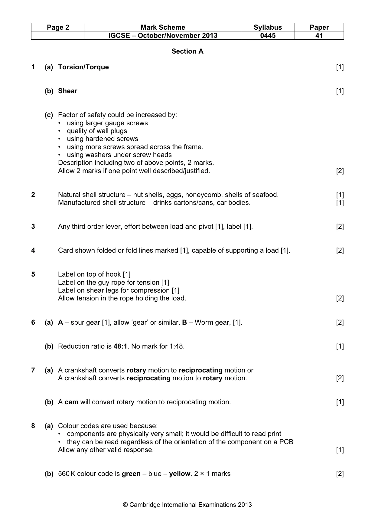
Page 2 Mark Scheme Syllabus Paper IGCSE – October/November 2013 0445 41 © Cambridge International Examinations 2013 Section A 1 (a) Torsion/Torque [1] (b) Shear [1] (c) Factor of safety could be increased by: • using larger gauge screws • quality of wall plugs • using hardened screws • using more screws spread across the frame. • using washers under screw heads Description including two of above points, 2 marks. Allow 2 marks if one point well described/justified. [2] 2 Natural shell structure – nut shells, eggs, honeycomb, shells of seafood. [1] Manufactured shell structure – drinks cartons/cans, car bodies. [1] 3 Any third order lever, effort between load and pivot [1], label [1]. [2] 4 Card shown folded or fold lines marked [1], capable of supporting a load [1]. [2] 5 Label on top of hook [1] Label on the guy rope for tension [1] Label on shear legs for compression [1] Allow tension in the rope holding the load. [2] 6 (a) A – spur gear [1], allow ‘gear’ or similar. B – Worm gear, [1]. [2] (b) Reduction ratio is 48:1. No mark for 1:48. [1] 7 (a) A crankshaft converts rotary motion to reciprocating motion or A crankshaft converts reciprocating motion to rotary motion. [2] (b) A cam will convert rotary motion to reciprocating motion. [1] 8 (a) Colour codes are used because: • components are physically very small; it would be difficult to read print • they can be read regardless of the orientation of the component on a PCB Allow any other valid response. [1] (b) 560 K colour code is green – blue – yellow. 2 × 1 marks [2]
Mark scheme, page 3
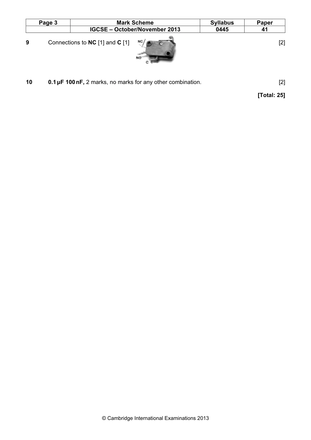
Page 3 Mark Scheme Syllabus Paper IGCSE – October/November 2013 0445 41 © Cambridge International Examinations 2013 9 Connections to NC [1] and C [1] [2] 10 0.1 µF 100 nF, 2 marks, no marks for any other combination. [2] [Total: 25]
Mark scheme, page 4
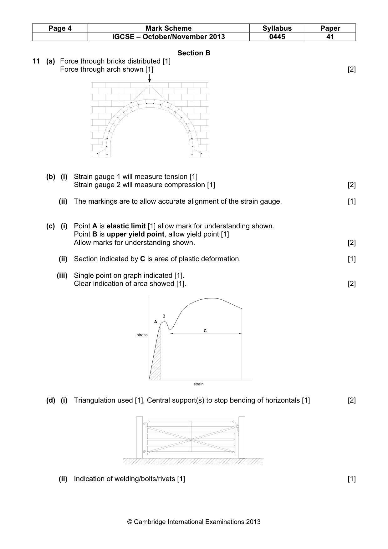
Page 4 Mark Scheme Syllabus Paper IGCSE – October/November 2013 0445 41 © Cambridge International Examinations 2013 Section B 11 (a) Force through bricks distributed [1] Force through arch shown [1] [2] (b) (i) Strain gauge 1 will measure tension [1] Strain gauge 2 will measure compression [1] [2] (ii) The markings are to allow accurate alignment of the strain gauge. [1] (c) (i) Point A is elastic limit [1] allow mark for understanding shown. Point B is upper yield point, allow yield point [1] Allow marks for understanding shown. [2] (ii) Section indicated by C is area of plastic deformation. [1] (iii) Single point on graph indicated [1]. Clear indication of area showed [1]. [2] (d) (i) Triangulation used [1], Central support(s) to stop bending of horizontals [1] [2] (ii) Indication of welding/bolts/rivets [1] [1] A B C stress strain
Mark scheme, page 5
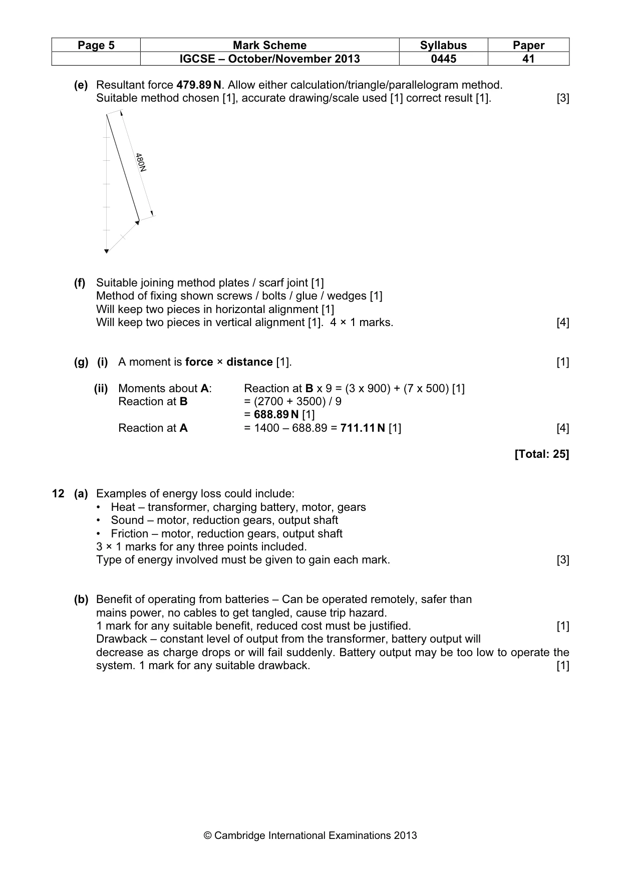
Page 5 Mark Scheme Syllabus Paper IGCSE – October/November 2013 0445 41 © Cambridge International Examinations 2013 (e) Resultant force 479.89 N. Allow either calculation/triangle/parallelogram method. Suitable method chosen [1], accurate drawing/scale used [1] correct result [1]. [3] (f) Suitable joining method plates / scarf joint [1] Method of fixing shown screws / bolts / glue / wedges [1] Will keep two pieces in horizontal alignment [1] Will keep two pieces in vertical alignment [1]. 4 × 1 marks. [4] (g) (i) A moment is force × distance [1]. [1] (ii) Moments about A: Reaction at B x 9 = (3 x 900) + (7 x 500) [1] Reaction at B = (2700 + 3500) / 9 = 688.89 N [1] Reaction at A = 1400 – 688.89 = 711.11 N [1] [4] [Total: 25] 12 (a) Examples of energy loss could include: • Heat – transformer, charging battery, motor, gears • Sound – motor, reduction gears, output shaft • Friction – motor, reduction gears, output shaft 3 × 1 marks for any three points included. Type of energy involved must be given to gain each mark. [3] (b) Benefit of operating from batteries – Can be operated remotely, safer than mains power, no cables to get tangled, cause trip hazard. 1 mark for any suitable benefit, reduced cost must be justified. [1] Drawback – constant level of output from the transformer, battery output will decrease as charge drops or will fail suddenly. Battery output may be too low to operate the system. 1 mark for any suitable drawback. [1] 480N
Mark scheme, page 6
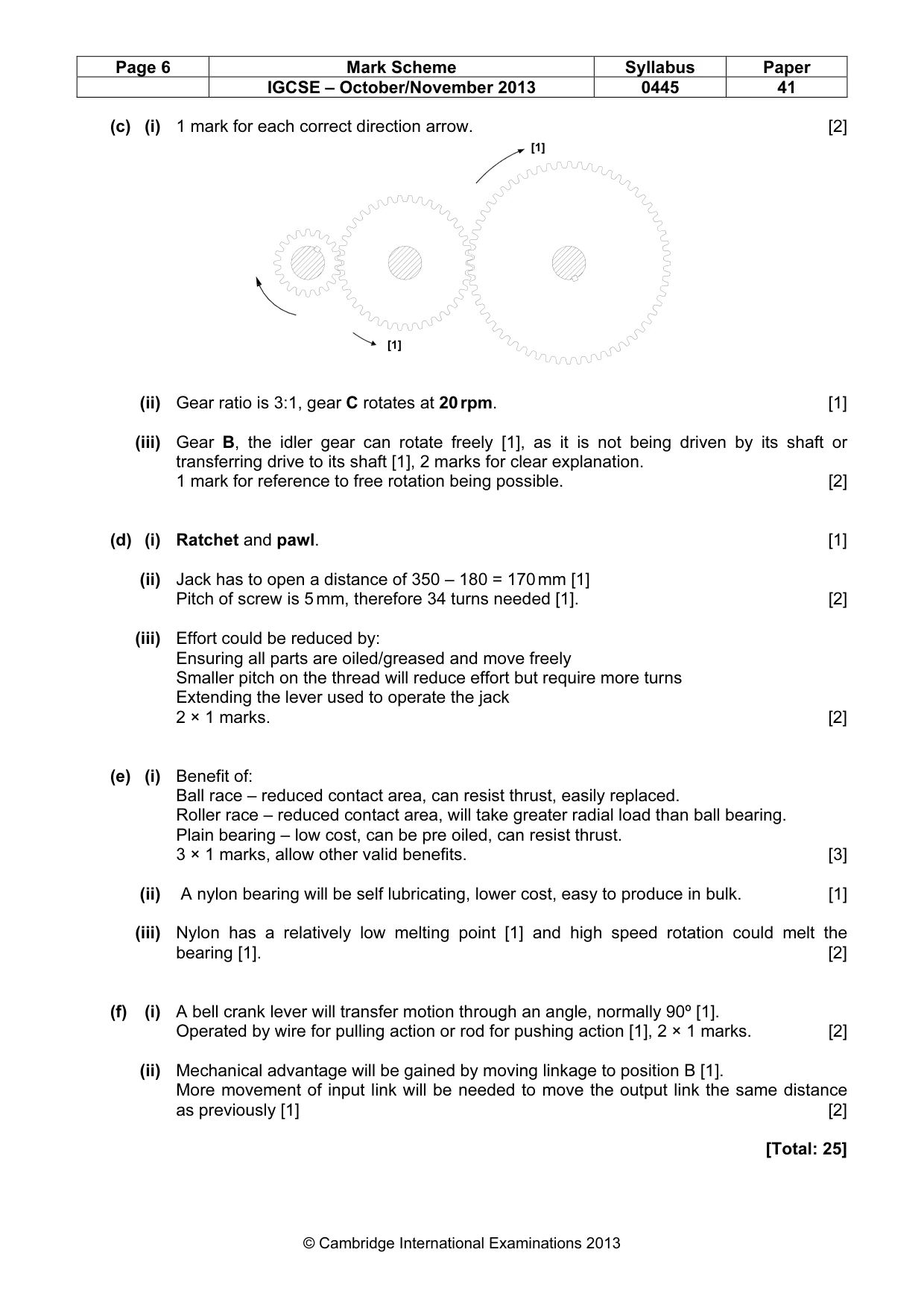
Page 6 Mark Scheme Syllabus Paper IGCSE – October/November 2013 0445 41 © Cambridge International Examinations 2013 (c) (i) 1 mark for each correct direction arrow. [2] (ii) Gear ratio is 3:1, gear C rotates at 20 rpm. [1] (iii) Gear B, the idler gear can rotate freely [1], as it is not being driven by its shaft or transferring drive to its shaft [1], 2 marks for clear explanation. 1 mark for reference to free rotation being possible. [2] (d) (i) Ratchet and pawl. [1] (ii) Jack has to open a distance of 350 – 180 = 170 mm [1] Pitch of screw is 5 mm, therefore 34 turns needed [1]. [2] (iii) Effort could be reduced by: Ensuring all parts are oiled/greased and move freely Smaller pitch on the thread will reduce effort but require more turns Extending the lever used to operate the jack 2 × 1 marks. [2] (e) (i) Benefit of: Ball race – reduced contact area, can resist thrust, easily replaced. Roller race – reduced contact area, will take greater radial load than ball bearing. Plain bearing – low cost, can be pre oiled, can resist thrust. 3 × 1 marks, allow other valid benefits. [3] (ii) A nylon bearing will be self lubricating, lower cost, easy to produce in bulk. [1] (iii) Nylon has a relatively low melting point [1] and high speed rotation could melt the bearing [1]. [2] (f) (i) A bell crank lever will transfer motion through an angle, normally 90º [1]. Operated by wire for pulling action or rod for pushing action [1], 2 × 1 marks. [2] (ii) Mechanical advantage will be gained by moving linkage to position B [1]. More movement of input link will be needed to move the output link the same distance as previously [1] [2] [Total: 25] [1] [1]
Mark scheme, page 7
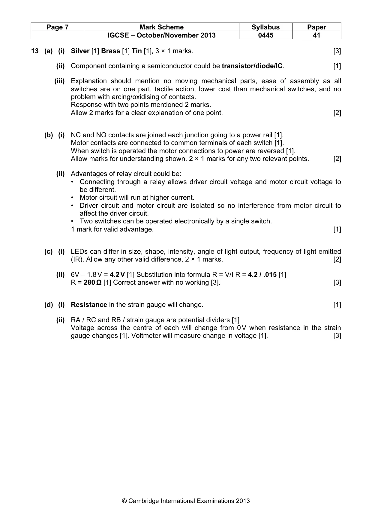
Page 7 Mark Scheme Syllabus Paper IGCSE – October/November 2013 0445 41 © Cambridge International Examinations 2013 13 (a) (i) Silver [1] Brass [1] Tin [1], 3 × 1 marks. [3] (ii) Component containing a semiconductor could be transistor/diode/IC. [1] (iii) Explanation should mention no moving mechanical parts, ease of assembly as all switches are on one part, tactile action, lower cost than mechanical switches, and no problem with arcing/oxidising of contacts. Response with two points mentioned 2 marks. Allow 2 marks for a clear explanation of one point. [2] (b) (i) NC and NO contacts are joined each junction going to a power rail [1]. Motor contacts are connected to common terminals of each switch [1]. When switch is operated the motor connections to power are reversed [1]. Allow marks for understanding shown. 2 × 1 marks for any two relevant points. [2] (ii) Advantages of relay circuit could be: • Connecting through a relay allows driver circuit voltage and motor circuit voltage to be different. • Motor circuit will run at higher current. • Driver circuit and motor circuit are isolated so no interference from motor circuit to affect the driver circuit. • Two switches can be operated electronically by a single switch. 1 mark for valid advantage. [1] (c) (i) LEDs can differ in size, shape, intensity, angle of light output, frequency of light emitted (IR). Allow any other valid difference, 2 × 1 marks. [2] (ii) 6V – 1.8 V = 4.2 V [1] Substitution into formula R = V/I R = 4.2 / .015 [1] R = 280 Ω [1] Correct answer with no working [3]. [3] (d) (i) Resistance in the strain gauge will change. [1] (ii) RA / RC and RB / strain gauge are potential dividers [1] Voltage across the centre of each will change from 0 V when resistance in the strain gauge changes [1]. Voltmeter will measure change in voltage [1]. [3]
Mark scheme, page 8
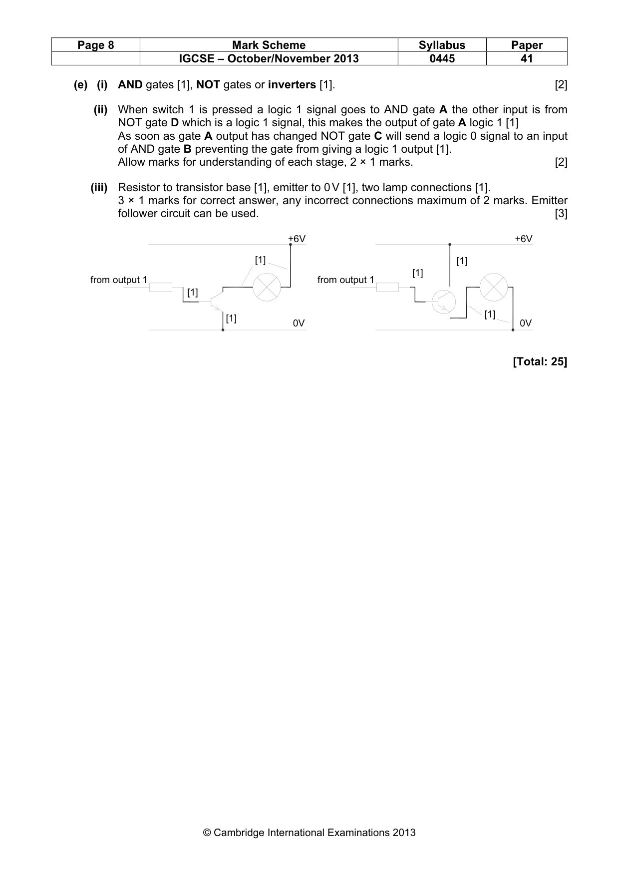
Page 8 Mark Scheme Syllabus Paper IGCSE – October/November 2013 0445 41 © Cambridge International Examinations 2013 (e) (i) AND gates [1], NOT gates or inverters [1]. [2] (ii) When switch 1 is pressed a logic 1 signal goes to AND gate A the other input is from NOT gate D which is a logic 1 signal, this makes the output of gate A logic 1 [1] As soon as gate A output has changed NOT gate C will send a logic 0 signal to an input of AND gate B preventing the gate from giving a logic 1 output [1]. Allow marks for understanding of each stage, 2 × 1 marks. [2] (iii) Resistor to transistor base [1], emitter to 0 V [1], two lamp connections [1]. 3 × 1 marks for correct answer, any incorrect connections maximum of 2 marks. Emitter follower circuit can be used. [3] [Total: 25] from output 1 +6V 0V [1] [1] [1] [1] [1] [1] from output 1 +6V 0V
What you needed in this session
Cambridge’s own grade thresholds for 2013 Oct/Nov, Paper 4 · Variant 1. A higher threshold means an easier paper — the bar moves with how the cohort did.