Cambridge IGCSE Design and Technology 0445 — 2012 Oct/Nov Paper 4 · Variant 1
0445/41/O/N/12 · 50 marks · ≈56 min
The question paper and its mark scheme, free to read here and free to download. This is Cambridge’s own paper, exactly as it was sat.
Question paper16 pages



Mark scheme8 pages
Answers below. Sit the paper first if you are practising.
Paper as text
Question paper, page 1
[Turn over *9345501075* READ THESE INSTRUCTIONS FIRST Write your Centre number, candidate number and name on all the work you hand in. Write in dark blue or black pen. You may use a soft pencil for any diagrams or graphs. Do not use staples, paper clips, highlighters, glue or correction fl uid. DO NOT WRITE IN ANY BARCODES. You may use a calculator. Section A Answer all questions. Section B Answer one question. At the end of the examination, fasten all your work securely together. The number of marks is given in brackets [ ] at the end of each question or part question. For Examiner’s Use Section A Section B Total DESIGN AND TECHNOLOGY 0445/41 Paper 4 Systems and Control October/November 2012 1 hour Candidates answer on the Question Paper. No Additional Materials are required. To be taken together with Paper 1 in one session of 2 hours and 15 minutes. UNIVERSITY OF CAMBRIDGE INTERNATIONAL EXAMINATIONS International General Certifi cate of Secondary Education This document consists of an 16 printed pages. [Turn over IB12 11_0445_41/5RP © UCLES 2012 www.XtremePapers.com
Question paper, page 2
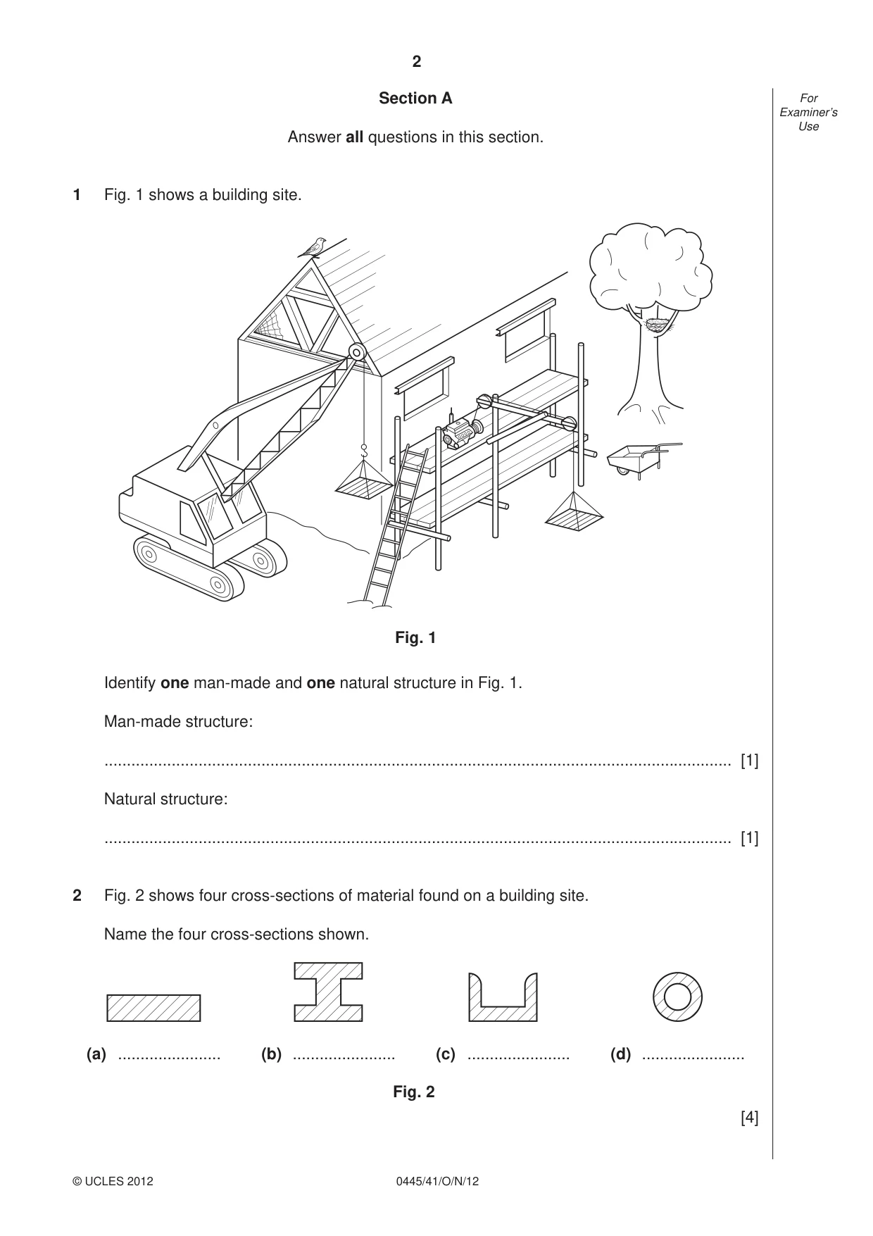
2 0445/41/O/N/12 © UCLES 2012 For Examiner’s Use Section A Answer all questions in this section. 1 Fig. 1 shows a building site. Fig. 1 Identify one man-made and one natural structure in Fig. 1. Man-made structure: … [1] Natural structure: … [1] 2 Fig. 2 shows four cross-sections of material found on a building site. Name the four cross-sections shown. (a) … (b) … (c) … (d) … Fig. 2 [4]
Question paper, page 3
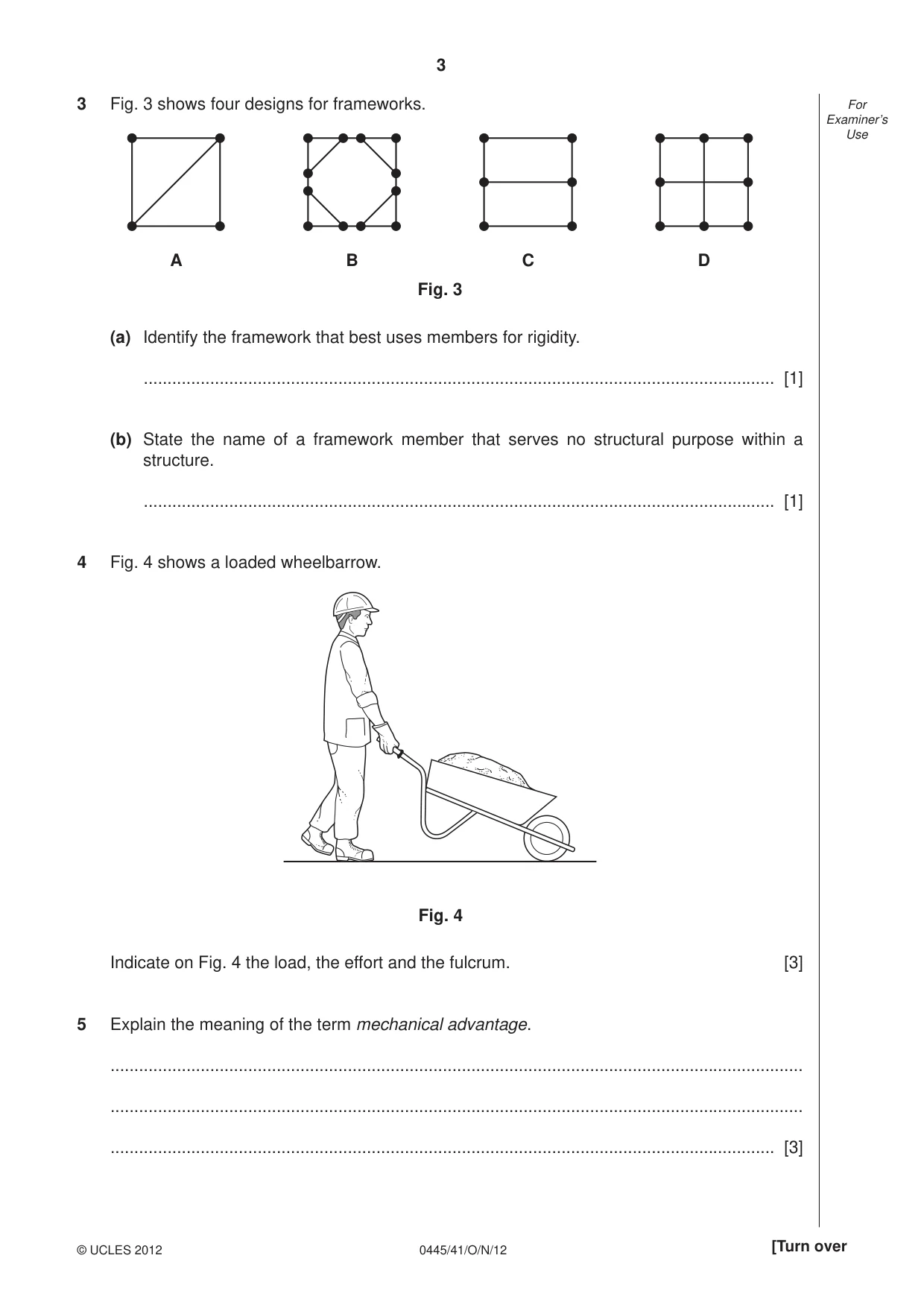
3 0445/41/O/N/12 © UCLES 2012 [Turn over For Examiner’s Use 3 Fig. 3 shows four designs for frameworks. A B Fig. 3 C D (a) Identify the framework that best uses members for rigidity. … [1] (b) State the name of a framework member that serves no structural purpose within a structure. … [1] 4 Fig. 4 shows a loaded wheelbarrow. Fig. 4 Indicate on Fig. 4 the load, the effort and the fulcrum. [3] 5 Explain the meaning of the term mechanical advantage. … … … [3]
Question paper, page 4
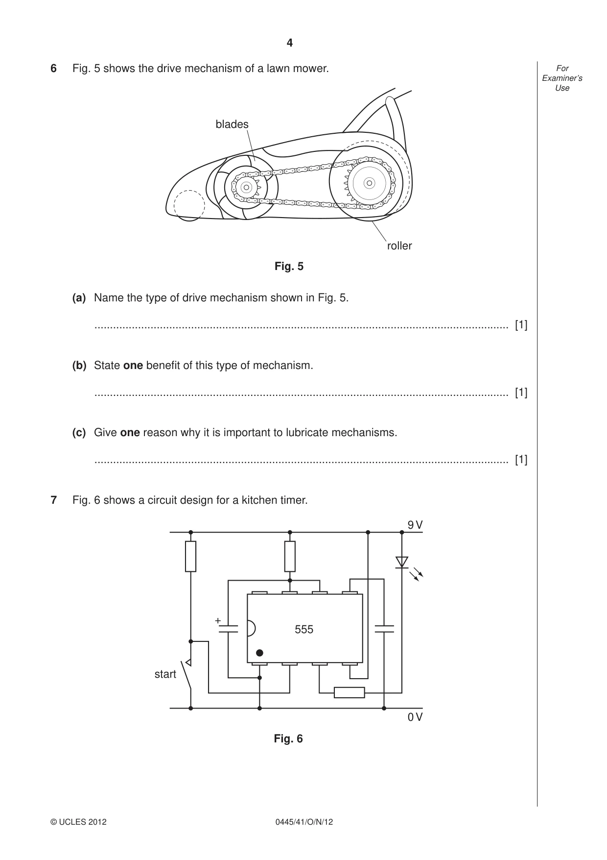
4 0445/41/O/N/12 © UCLES 2012 For Examiner’s Use 6 Fig. 5 shows the drive mechanism of a lawn mower. blades roller Fig. 5 (a) Name the type of drive mechanism shown in Fig. 5. … [1] (b) State one benefi t of this type of mechanism. … [1] (c) Give one reason why it is important to lubricate mechanisms. … [1] 7 Fig. 6 shows a circuit design for a kitchen timer. start 9 V 0 V Fig. 6 555 +
Question paper, page 5
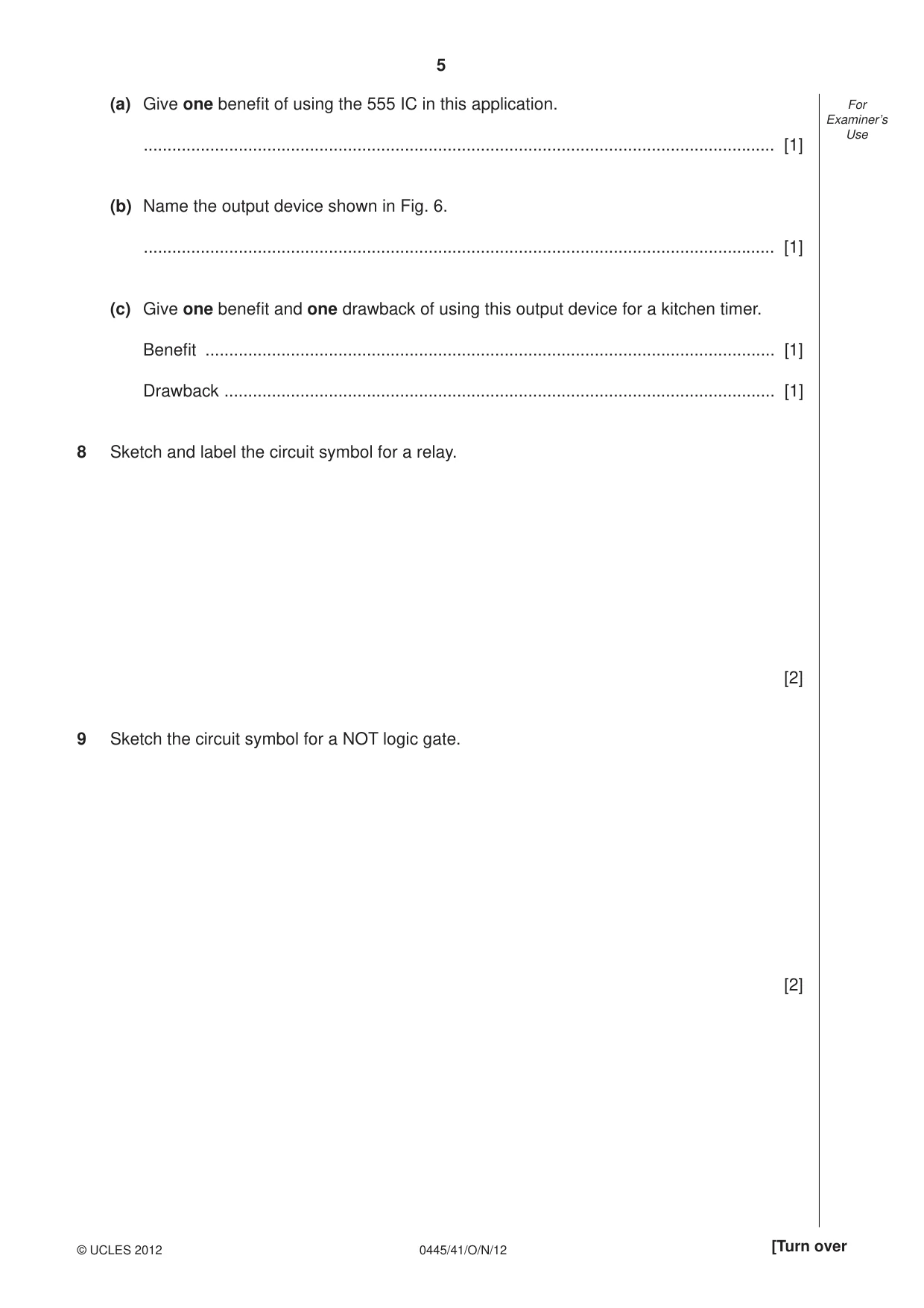
5 0445/41/O/N/12 © UCLES 2012 [Turn over For Examiner’s Use (a) Give one benefi t of using the 555 IC in this application. … [1] (b) Name the output device shown in Fig. 6. … [1] (c) Give one benefi t and one drawback of using this output device for a kitchen timer. Benefi t … [1] Drawback … [1] 8 Sketch and label the circuit symbol for a relay. [2] 9 Sketch the circuit symbol for a NOT logic gate. [2]
Question paper, page 6
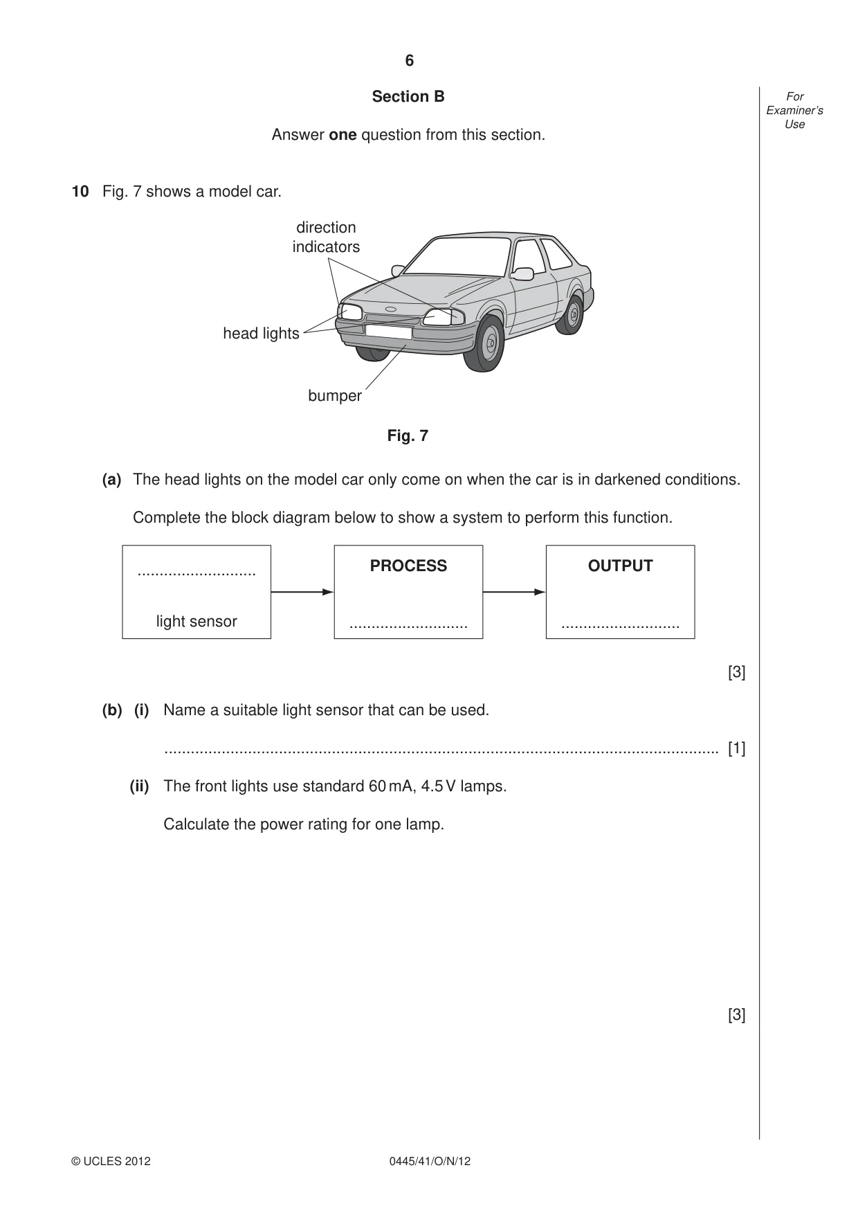
6 0445/41/O/N/12 © UCLES 2012 For Examiner’s Use Section B Answer one question from this section. 10 Fig. 7 shows a model car. head lights direction indicators bumper Fig. 7 (a) The head lights on the model car only come on when the car is in darkened conditions. Complete the block diagram below to show a system to perform this function. … light sensor PROCESS … OUTPUT … [3] (b) (i) Name a suitable light sensor that can be used. … [1] (ii) The front lights use standard 60 mA, 4.5 V lamps. Calculate the power rating for one lamp. [3]
Question paper, page 7
7 0445/41/O/N/12 © UCLES 2012 [Turn over For Examiner’s Use (iii) The power source for the lamps is a 9 V battery. Use a sketch to show how the lamps and battery would need to be arranged. [2] (iv) Draw the circuit diagram of a simple circuit that could be used to turn the head lights on in the dark. You should include the light sensor you have named in (b)(i). [5]
Question paper, page 8
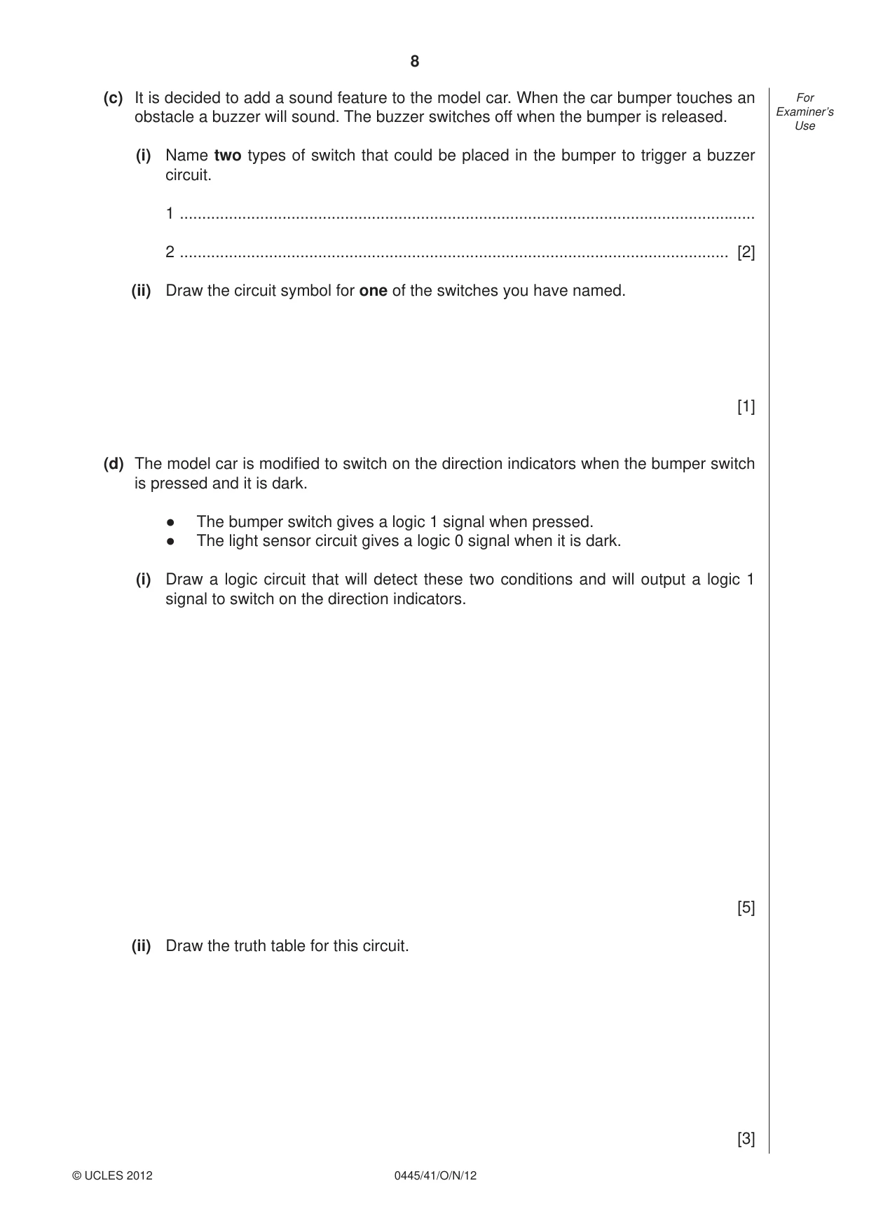
8 0445/41/O/N/12 © UCLES 2012 For Examiner’s Use (c) It is decided to add a sound feature to the model car. When the car bumper touches an obstacle a buzzer will sound. The buzzer switches off when the bumper is released. (i) Name two types of switch that could be placed in the bumper to trigger a buzzer circuit. 1 … 2 … [2] (ii) Draw the circuit symbol for one of the switches you have named. [1] (d) The model car is modifi ed to switch on the direction indicators when the bumper switch is pressed and it is dark. ● The bumper switch gives a logic 1 signal when pressed. ● The light sensor circuit gives a logic 0 signal when it is dark. (i) Draw a logic circuit that will detect these two conditions and will output a logic 1 signal to switch on the direction indicators. [5] (ii) Draw the truth table for this circuit. [3]
Question paper, page 9
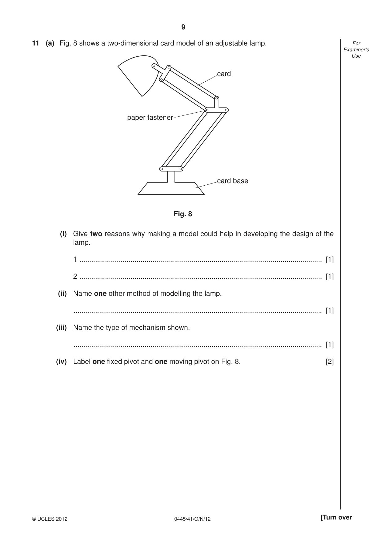
9 0445/41/O/N/12 © UCLES 2012 [Turn over For Examiner’s Use 11 (a) Fig. 8 shows a two-dimensional card model of an adjustable lamp. Fig. 8 card base card paper fastener (i) Give two reasons why making a model could help in developing the design of the lamp. 1 … [1] 2 … [1] (ii) Name one other method of modelling the lamp. … [1] (iii) Name the type of mechanism shown. … [1] (iv) Label one fi xed pivot and one moving pivot on Fig. 8. [2]
Question paper, page 10
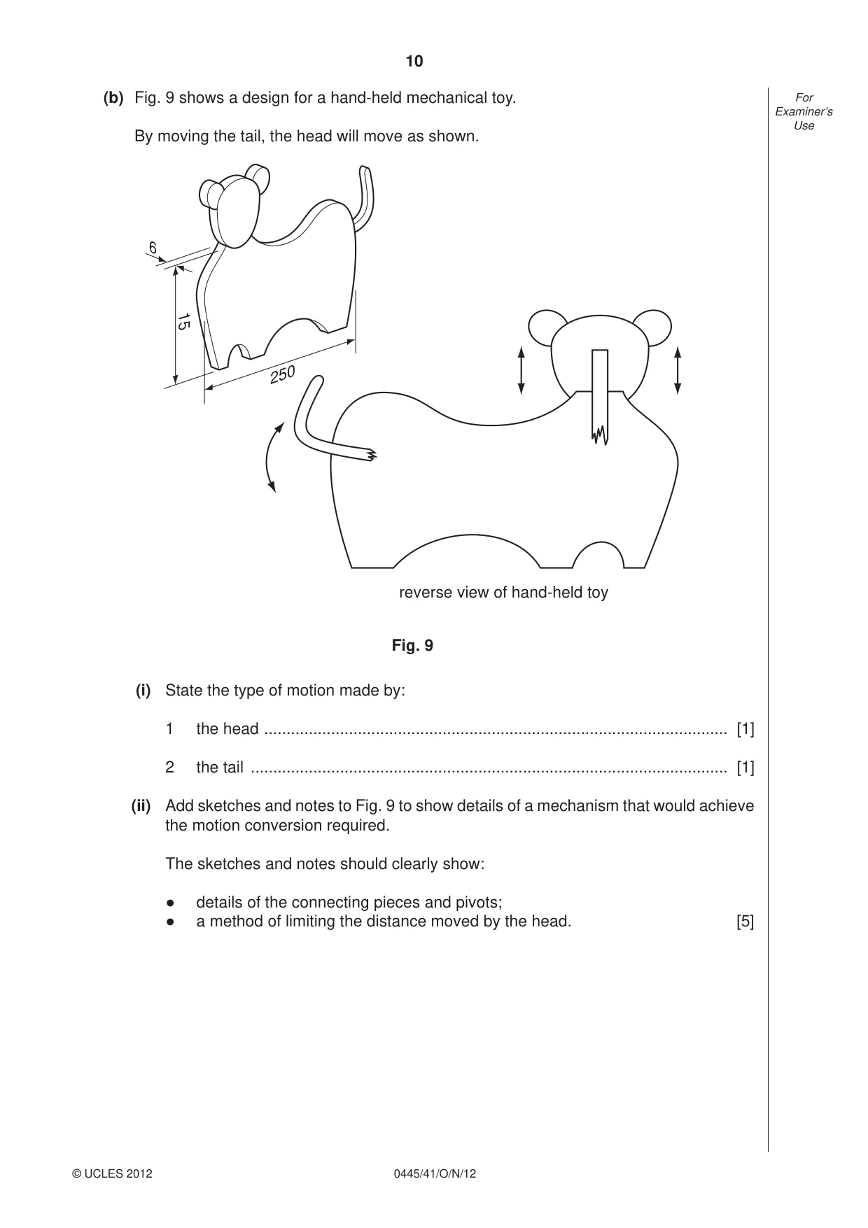
10 0445/41/O/N/12 © UCLES 2012 For Examiner’s Use (b) Fig. 9 shows a design for a hand-held mechanical toy. By moving the tail, the head will move as shown. reverse view of hand-held toy 250 15 6 Fig. 9 (i) State the type of motion made by: 1 the head … [1] 2 the tail … [1] (ii) Add sketches and notes to Fig. 9 to show details of a mechanism that would achieve the motion conversion required. The sketches and notes should clearly show: ● details of the connecting pieces and pivots; ● a method of limiting the distance moved by the head. [5]
Question paper, page 11
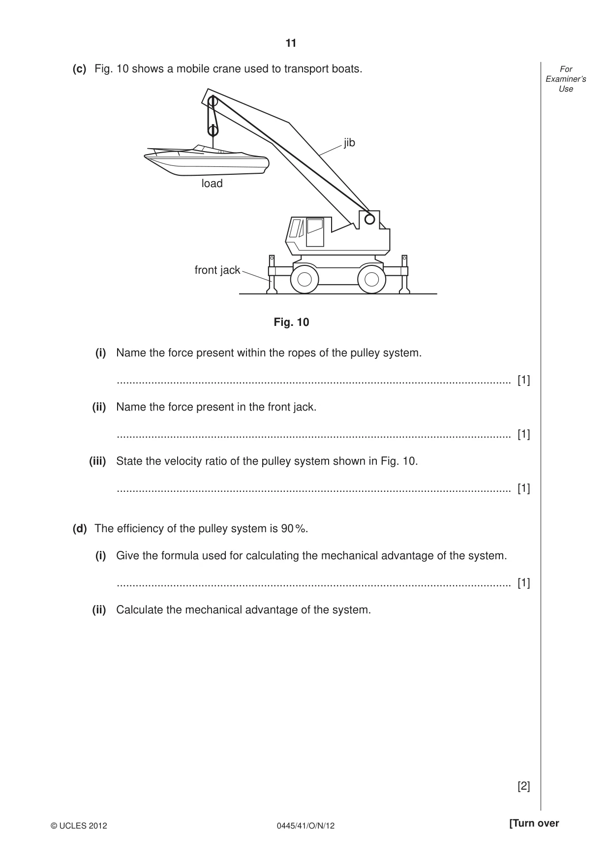
11 0445/41/O/N/12 © UCLES 2012 [Turn over For Examiner’s Use (c) Fig. 10 shows a mobile crane used to transport boats. load jib front jack Fig. 10 (i) Name the force present within the ropes of the pulley system. … [1] (ii) Name the force present in the front jack. … [1] (iii) State the velocity ratio of the pulley system shown in Fig. 10. … [1] (d) The effi ciency of the pulley system is 90 %. (i) Give the formula used for calculating the mechanical advantage of the system. … [1] (ii) Calculate the mechanical advantage of the system. [2]
Question paper, page 12
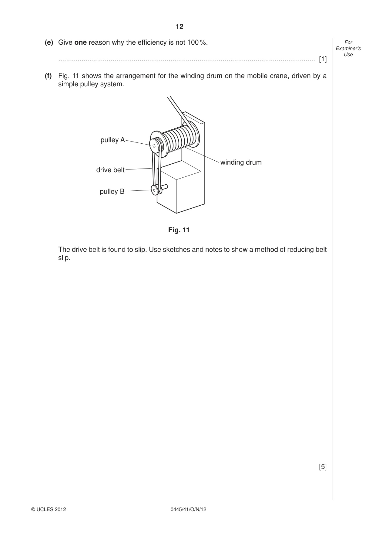
12 0445/41/O/N/12 © UCLES 2012 For Examiner’s Use (e) Give one reason why the effi ciency is not 100 %. … [1] (f) Fig. 11 shows the arrangement for the winding drum on the mobile crane, driven by a simple pulley system. pulley A pulley B drive belt winding drum Fig. 11 The drive belt is found to slip. Use sketches and notes to show a method of reducing belt slip. [5]
Question paper, page 13
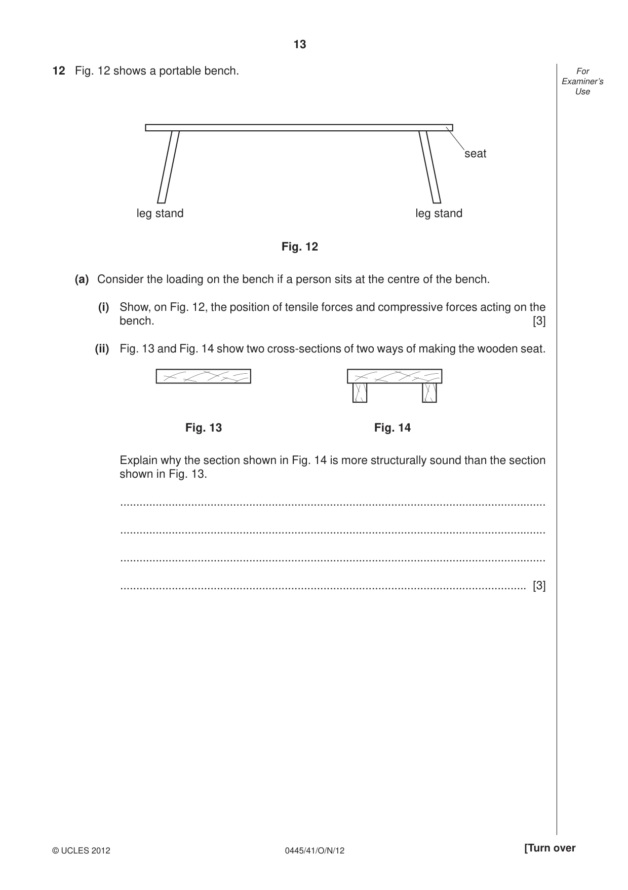
13 0445/41/O/N/12 © UCLES 2012 [Turn over For Examiner’s Use 12 Fig. 12 shows a portable bench. leg stand leg stand Fig. 12 seat (a) Consider the loading on the bench if a person sits at the centre of the bench. (i) Show, on Fig. 12, the position of tensile forces and compressive forces acting on the bench. [3] (ii) Fig. 13 and Fig. 14 show two cross-sections of two ways of making the wooden seat. Fig. 13 Fig. 14 Explain why the section shown in Fig. 14 is more structurally sound than the section shown in Fig. 13. … … … … [3]
Question paper, page 14
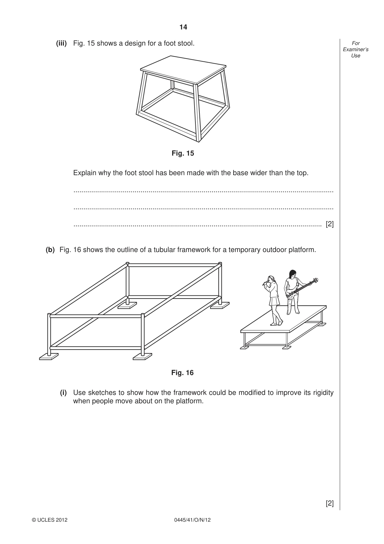
14 0445/41/O/N/12 © UCLES 2012 For Examiner’s Use (iii) Fig. 15 shows a design for a foot stool. Fig. 15 Explain why the foot stool has been made with the base wider than the top. … … … [2] (b) Fig. 16 shows the outline of a tubular framework for a temporary outdoor platform. Fig. 16 (i) Use sketches to show how the framework could be modifi ed to improve its rigidity when people move about on the platform. [2]
Question paper, page 15
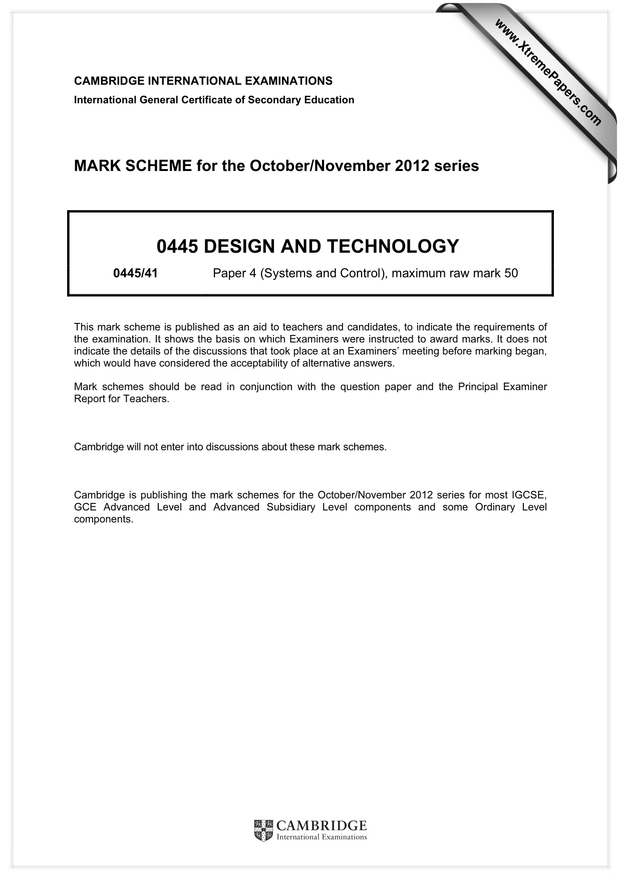
15 0445/41/O/N/12 © UCLES 2012 [Turn over For Examiner’s Use (ii) Use sketches and notes to show a joining method that could be used on the tubular framework, so that it is easy to put together and take apart. [3] (iii) Fig. 17 shows an enlarged view of one foot of the framework. 150 150 P T Fig. 17 Explain the purpose of the plate P of the foot. … … … [3] (iv) If the force on the plate is 1 kN and the plate measures 150 mm × 150 mm, calculate the pressure exerted on the ground. [2] (v) Plate P is permanently joined onto the tube T of the foot by welding. State one temporary method that could be used to join the plate P to the tube T. … [1] (vi) Give one other specifi c example of the use of the method you have stated in part (v). … [1]
Question paper, page 16
16 Permission to reproduce items where third-party owned material protected by copyright is included has been sought and cleared where possible. Every reasonable effort has been made by the publisher (UCLES) to trace copyright holders, but if any items requiring clearance have unwittingly been included the publisher will be pleased to make amends at the earliest possible opportunity. University of Cambridge International Examinations is part of the Cambridge Assessment Group. Cambridge Assessment is the brand name of University of Cambridge Local Examinations Syndicate (UCLES), which is itself a department of the University of Cambridge. 0445/41/O/N/12 © UCLES 2012 For Examiner’s Use (c) Fig. 18 shows a design for a toy boat hull. 70 40 80 150 400 Fig. 18 (i) Name the type of structure of the toy boat hull. … [1] (ii) The toy boat hull is found to be too fl exible. Explain, using sketches and notes, how it would be made more rigid. [4]
Mark scheme, page 1
CAMBRIDGE INTERNATIONAL EXAMINATIONS International General Certificate of Secondary Education MARK SCHEME for the October/November 2012 series 0445 DESIGN AND TECHNOLOGY 0445/41 Paper 4 (Systems and Control), maximum raw mark 50 This mark scheme is published as an aid to teachers and candidates, to indicate the requirements of the examination. It shows the basis on which Examiners were instructed to award marks. It does not indicate the details of the discussions that took place at an Examiners’ meeting before marking began, which would have considered the acceptability of alternative answers. Mark schemes should be read in conjunction with the question paper and the Principal Examiner Report for Teachers. Cambridge will not enter into discussions about these mark schemes. Cambridge is publishing the mark schemes for the October/November 2012 series for most IGCSE, GCE Advanced Level and Advanced Subsidiary Level components and some Ordinary Level components. www.XtremePapers.com
Mark scheme, page 2
Page 2 Mark Scheme Syllabus Paper IGCSE – October/November 2012 0445 41 © Cambridge International Examinations 2012 Section A 1 Roof truss / crane / scaffold / fence / ladder [1] Spider’s web / bird (skeleton) / tree / nest [1] 2 (a) Rectangular (1) (b) ‘I’ Section (1) (c) ‘U’ Section (1) (d) Circular tube (1) [4] 3 (a) Framework A [1] (b) Redundant [1] 4 Effort (1) load (1) fulcrum (1) [3] 5 How a mechanism / machine reduces the effort (1) needed to perform a task (1), making work easier for the operator (1) calculated by load / effort (1) Any three individual points included or two points clearly explained [3]
Mark scheme, page 3
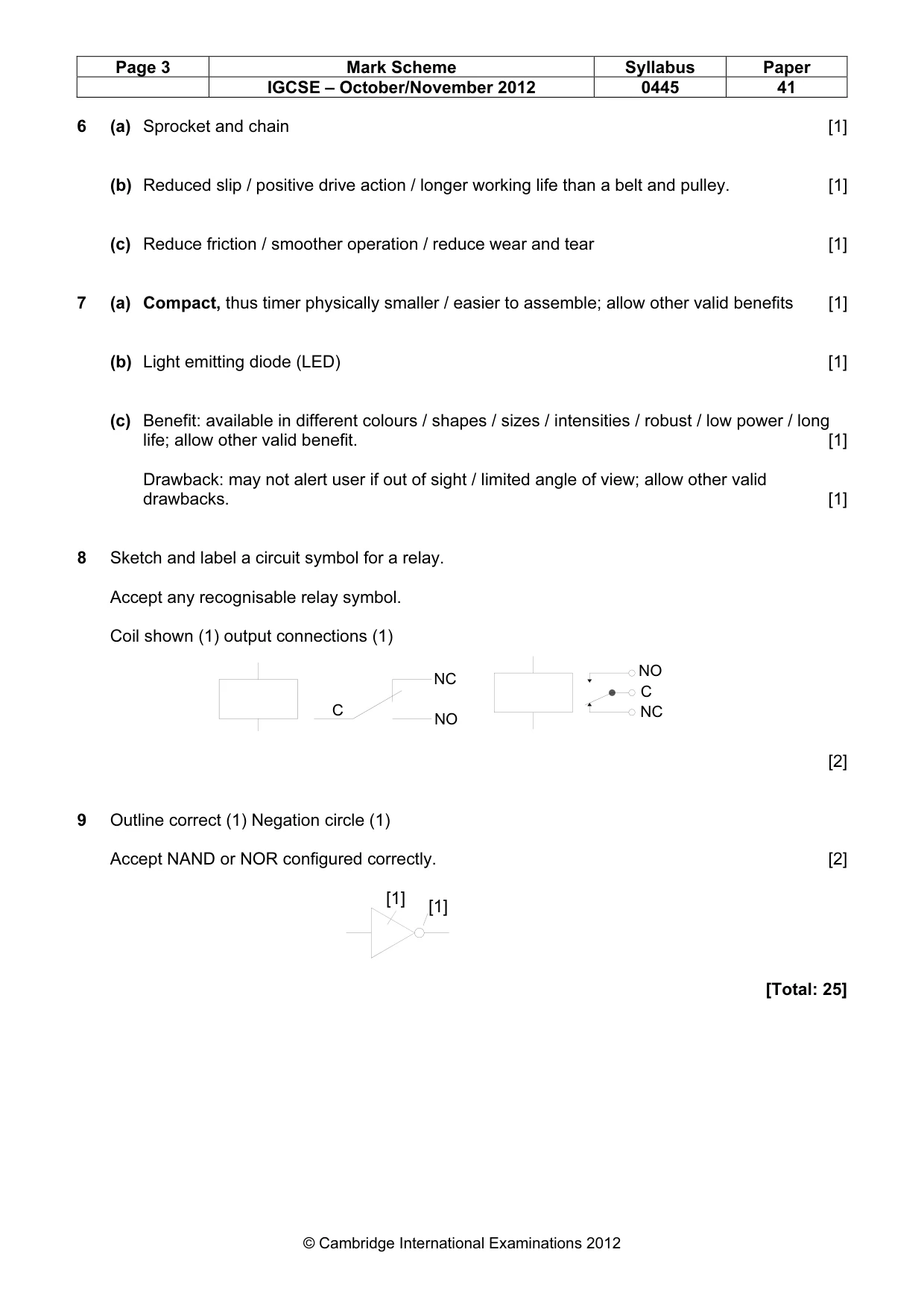
Page 3 Mark Scheme Syllabus Paper IGCSE – October/November 2012 0445 41 © Cambridge International Examinations 2012 6 (a) Sprocket and chain [1] (b) Reduced slip / positive drive action / longer working life than a belt and pulley. [1] (c) Reduce friction / smoother operation / reduce wear and tear [1] 7 (a) Compact, thus timer physically smaller / easier to assemble; allow other valid benefits [1] (b) Light emitting diode (LED) [1] (c) Benefit: available in different colours / shapes / sizes / intensities / robust / low power / long life; allow other valid benefit. [1] Drawback: may not alert user if out of sight / limited angle of view; allow other valid drawbacks. [1] 8 Sketch and label a circuit symbol for a relay. Accept any recognisable relay symbol. Coil shown (1) output connections (1) [2] 9 Outline correct (1) Negation circle (1) Accept NAND or NOR configured correctly. [2] [Total: 25] NO C NC NC NO C [1] [1]
Mark scheme, page 4
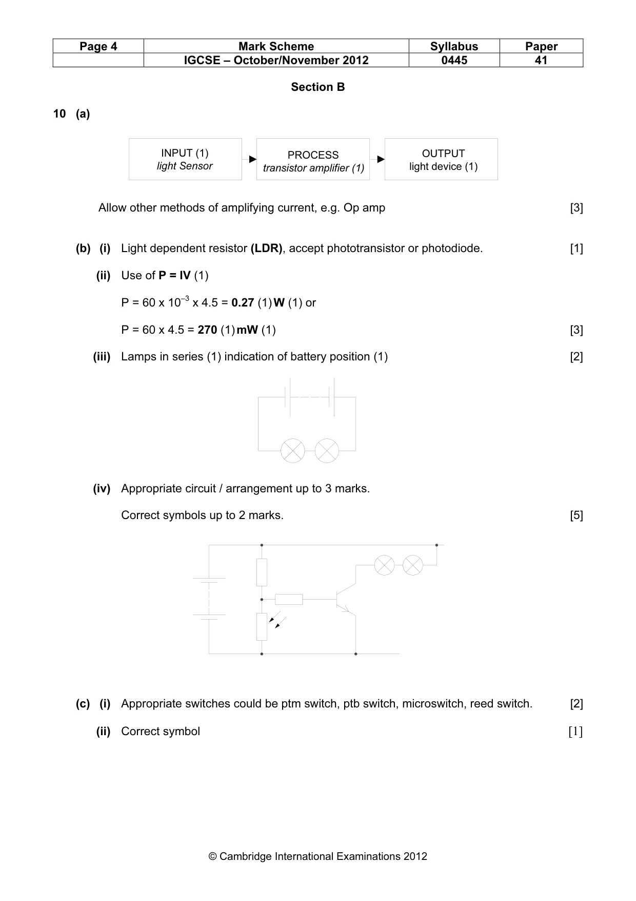
Page 4 Mark Scheme Syllabus Paper IGCSE – October/November 2012 0445 41 © Cambridge International Examinations 2012 Section B 10 (a) Allow other methods of amplifying current, e.g. Op amp [3] (b) (i) Light dependent resistor (LDR), accept phototransistor or photodiode. [1] (ii) Use of P = IV (1) P = 60 x 10–3 x 4.5 = 0.27 (1) W (1) or P = 60 x 4.5 = 270 (1) mW (1) [3] (iii) Lamps in series (1) indication of battery position (1) [2] (iv) Appropriate circuit / arrangement up to 3 marks. Correct symbols up to 2 marks. [5] (c) (i) Appropriate switches could be ptm switch, ptb switch, microswitch, reed switch. [2] (ii) Correct symbol [1] INPUT (1) light Sensor PROCESS transistor amplifier (1) OUTPUT light device (1)
Mark scheme, page 5
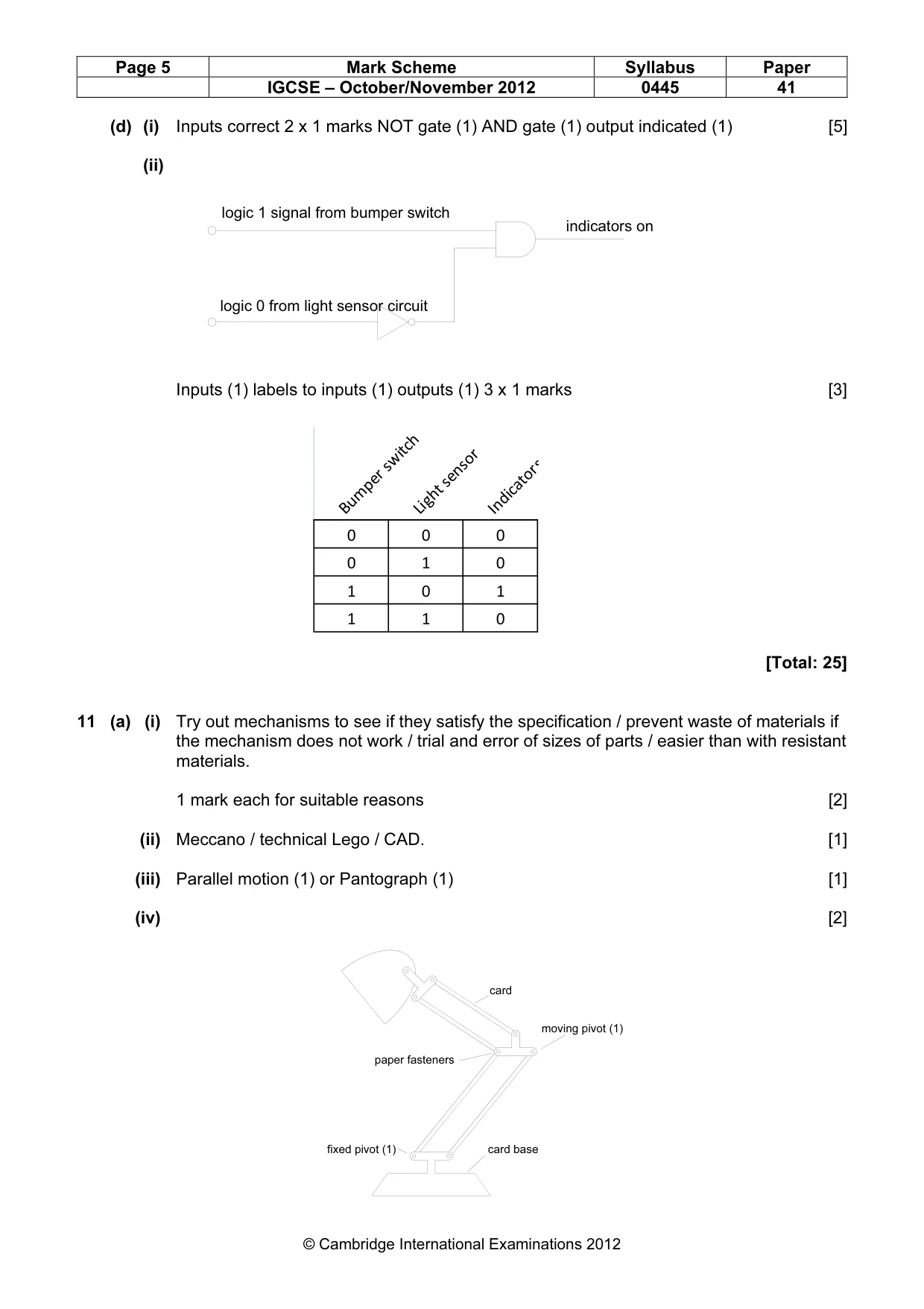
Page 5 Mark Scheme Syllabus Paper IGCSE – October/November 2012 0445 41 © Cambridge International Examinations 2012 (d) (i) Inputs correct 2 x 1 marks NOT gate (1) AND gate (1) output indicated (1) [5] (ii) Inputs (1) labels to inputs (1) outputs (1) 3 x 1 marks [3] [Total: 25] 11 (a) (i) Try out mechanisms to see if they satisfy the specification / prevent waste of materials if the mechanism does not work / trial and error of sizes of parts / easier than with resistant materials. 1 mark each for suitable reasons [2] (ii) Meccano / technical Lego / CAD. [1] (iii) Parallel motion (1) or Pantograph (1) [1] (iv) [2] logic 1 signal from bumper switch logic 0 from light sensor circuit indicators on Bumper switch Light sensor Indicators 0 0 0 0 1 0 1 0 1 1 1 0 card base paper fasteners card fixed pivot (1) moving pivot (1)
Mark scheme, page 6
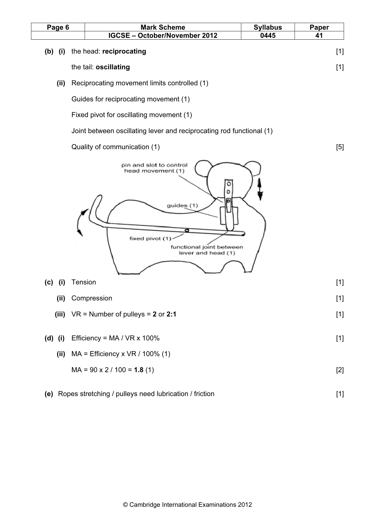
Page 6 Mark Scheme Syllabus Paper IGCSE – October/November 2012 0445 41 © Cambridge International Examinations 2012 (b) (i) the head: reciprocating [1] the tail: oscillating [1] (ii) Reciprocating movement limits controlled (1) Guides for reciprocating movement (1) Fixed pivot for oscillating movement (1) Joint between oscillating lever and reciprocating rod functional (1) Quality of communication (1) [5] (c) (i) Tension [1] (ii) Compression [1] (iii) VR = Number of pulleys = 2 or 2:1 [1] (d) (i) Efficiency = MA / VR x 100% [1] (ii) MA = Efficiency x VR / 100% (1) MA = 90 x 2 / 100 = 1.8 (1) [2] (e) Ropes stretching / pulleys need lubrication / friction [1]
Mark scheme, page 7
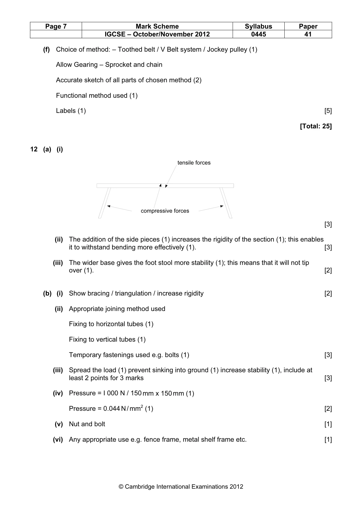
Page 7 Mark Scheme Syllabus Paper IGCSE – October/November 2012 0445 41 © Cambridge International Examinations 2012 (f) Choice of method: – Toothed belt / V Belt system / Jockey pulley (1) Allow Gearing – Sprocket and chain Accurate sketch of all parts of chosen method (2) Functional method used (1) Labels (1) [5] [Total: 25] 12 (a) (i) [3] (ii) The addition of the side pieces (1) increases the rigidity of the section (1); this enables it to withstand bending more effectively (1). [3] (iii) The wider base gives the foot stool more stability (1); this means that it will not tip over (1). [2] (b) (i) Show bracing / triangulation / increase rigidity [2] (ii) Appropriate joining method used Fixing to horizontal tubes (1) Fixing to vertical tubes (1) Temporary fastenings used e.g. bolts (1) [3] (iii) Spread the load (1) prevent sinking into ground (1) increase stability (1), include at least 2 points for 3 marks [3] (iv) Pressure = I 000 N / 150 mm x 150 mm (1) Pressure = 0.044 N / mm2 (1) [2] (v) Nut and bolt [1] (vi) Any appropriate use e.g. fence frame, metal shelf frame etc. [1] compressive forces tensile forces
Mark scheme, page 8
Page 8 Mark Scheme Syllabus Paper IGCSE – October/November 2012 0445 41 © Cambridge International Examinations 2012 (c) (i) Shell [1] (ii) The edges have a flange added (1) Drawings / labels (1) Adding ribs that run across the beam of the hull (1) Drawings / labels (1) [4] [Total: 25]
What you needed in this session
Cambridge’s own grade thresholds for 2012 Oct/Nov, Paper 4 · Variant 1. A higher threshold means an easier paper — the bar moves with how the cohort did.