Cambridge IGCSE Design and Technology 0445 — 2012 May/June Paper 4 · Variant 3
0445/43/M/J/12 · 50 marks · ≈56 min
The question paper and its mark scheme, free to read here and free to download. This is Cambridge’s own paper, exactly as it was sat.
Question paper16 pages
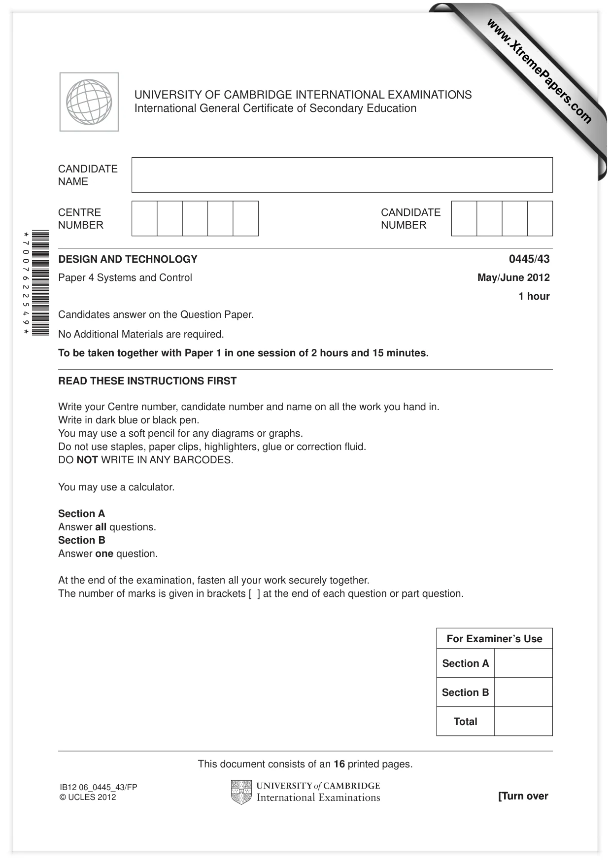
Mark scheme6 pages
Answers below. Sit the paper first if you are practising.
Paper as text
Question paper, page 1
[Turn over *7007622549* READ THESE INSTRUCTIONS FIRST Write your Centre number, candidate number and name on all the work you hand in. Write in dark blue or black pen. You may use a soft pencil for any diagrams or graphs. Do not use staples, paper clips, highlighters, glue or correction fl uid. DO NOT WRITE IN ANY BARCODES. You may use a calculator. Section A Answer all questions. Section B Answer one question. At the end of the examination, fasten all your work securely together. The number of marks is given in brackets [ ] at the end of each question or part question. For Examiner’s Use Section A Section B Total DESIGN AND TECHNOLOGY 0445/43 Paper 4 Systems and Control May/June 2012 1 hour Candidates answer on the Question Paper. No Additional Materials are required. To be taken together with Paper 1 in one session of 2 hours and 15 minutes. UNIVERSITY OF CAMBRIDGE INTERNATIONAL EXAMINATIONS International General Certifi cate of Secondary Education This document consists of an 16 printed pages. [Turn over IB12 06_0445_43/FP © UCLES 2012 www.XtremePapers.com
Question paper, page 2
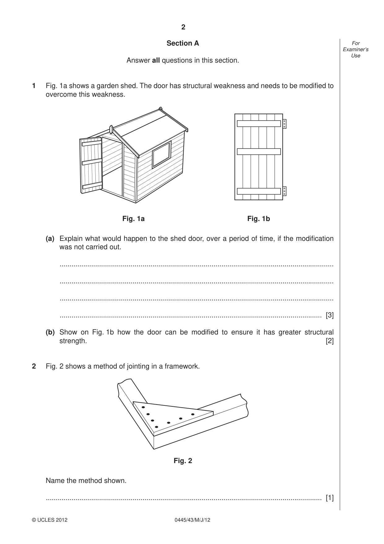
2 0445/43/M/J/12 © UCLES 2012 For Examiner’s Use Section A Answer all questions in this section. 1 Fig. 1a shows a garden shed. The door has structural weakness and needs to be modifi ed to overcome this weakness. Fig. 1a Fig. 1b (a) Explain what would happen to the shed door, over a period of time, if the modifi cation was not carried out. … … … … [3] (b) Show on Fig. 1b how the door can be modifi ed to ensure it has greater structural strength. [2] 2 Fig. 2 shows a method of jointing in a framework. Fig. 2 Name the method shown. … [1]
Question paper, page 3
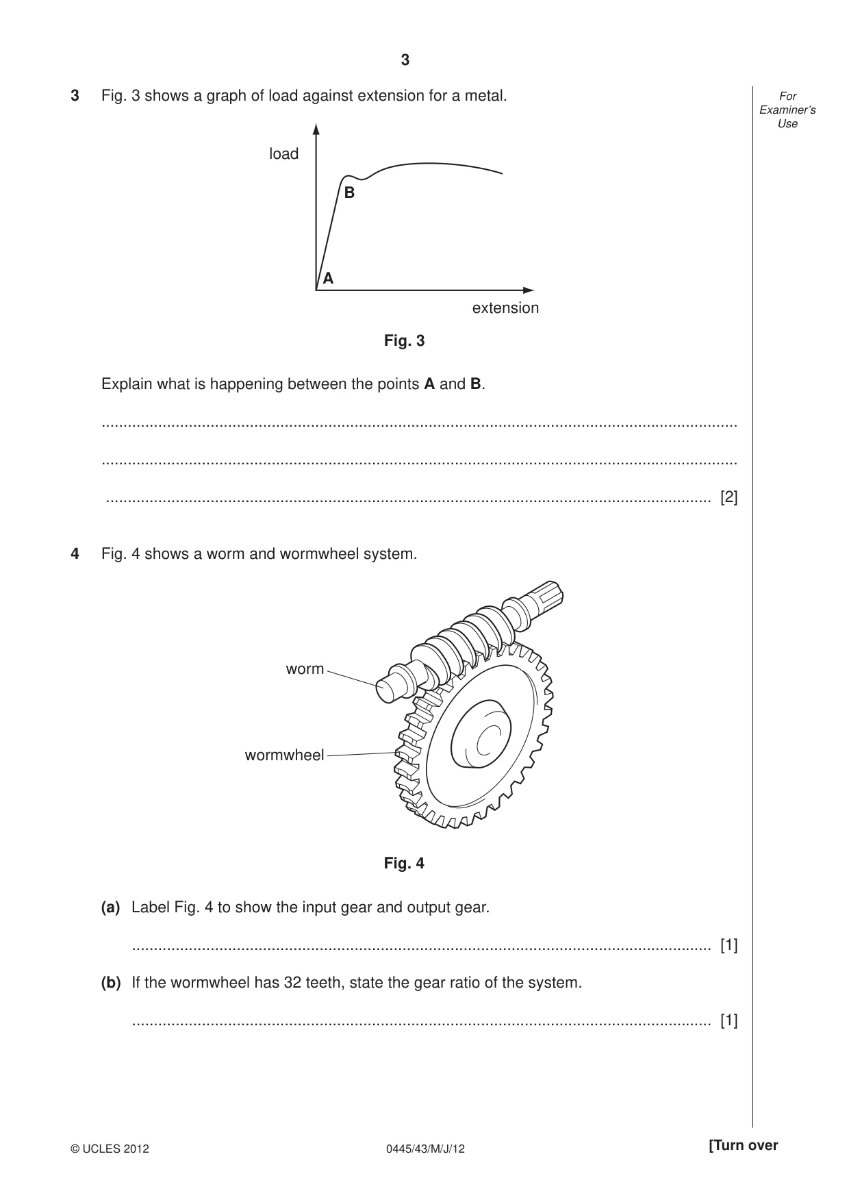
3 0445/43/M/J/12 © UCLES 2012 [Turn over For Examiner’s Use 3 Fig. 3 shows a graph of load against extension for a metal. load extension A B Fig. 3 Explain what is happening between the points A and B. … … … [2] 4 Fig. 4 shows a worm and wormwheel system. worm wormwheel Fig. 4 (a) Label Fig. 4 to show the input gear and output gear. … [1] (b) If the wormwheel has 32 teeth, state the gear ratio of the system. … [1]
Question paper, page 4
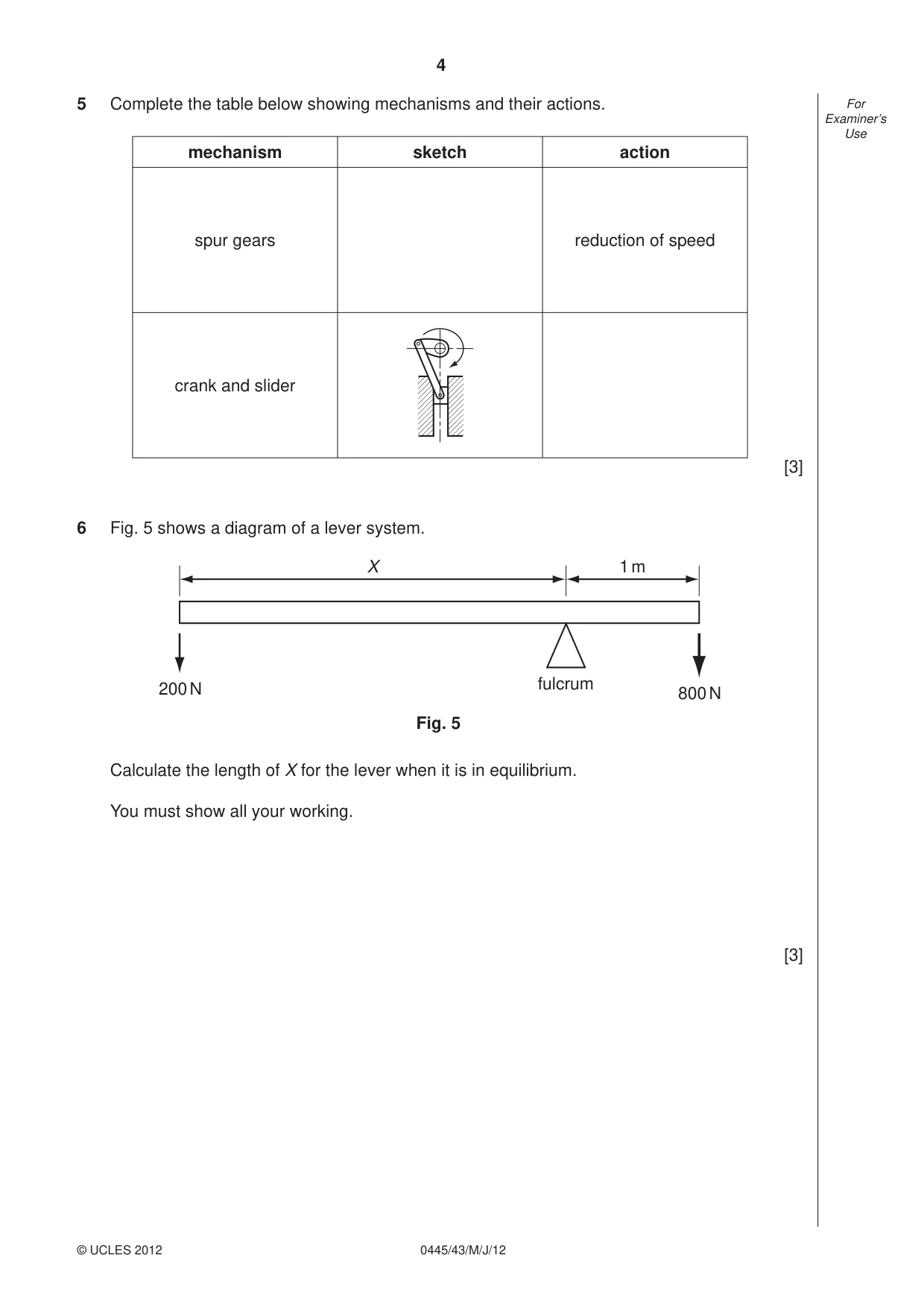
4 0445/43/M/J/12 © UCLES 2012 For Examiner’s Use 5 Complete the table below showing mechanisms and their actions. mechanism sketch action spur gears reduction of speed crank and slider [3] 6 Fig. 5 shows a diagram of a lever system. fulcrum 200 N 800 N 1 m X Fig. 5 Calculate the length of X for the lever when it is in equilibrium. You must show all your working. [3]
Question paper, page 5
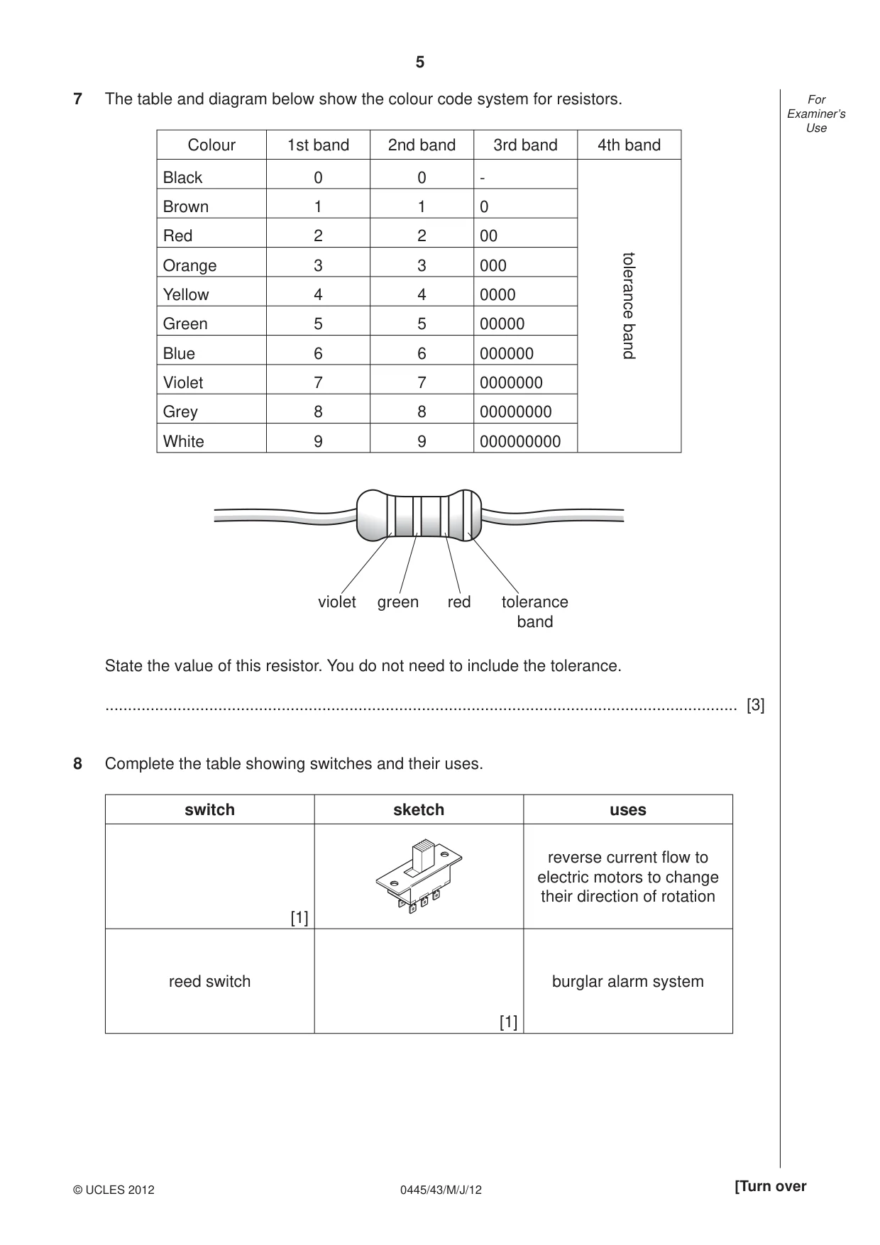
5 0445/43/M/J/12 © UCLES 2012 [Turn over For Examiner’s Use 7 The table and diagram below show the colour code system for resistors. Colour 1st band 2nd band 3rd band 4th band Black 0 0 - tolerance band Brown 1 1 0 Red 2 2 00 Orange 3 3 000 Yellow 4 4 0000 Green 5 5 00000 Blue 6 6 000000 Violet 7 7 0000000 Grey 8 8 00000000 White 9 9 000000000 violet green red tolerance band State the value of this resistor. You do not need to include the tolerance. … [3] 8 Complete the table showing switches and their uses. switch sketch uses [1] reverse current fl ow to electric motors to change their direction of rotation reed switch [1] burglar alarm system
Question paper, page 6
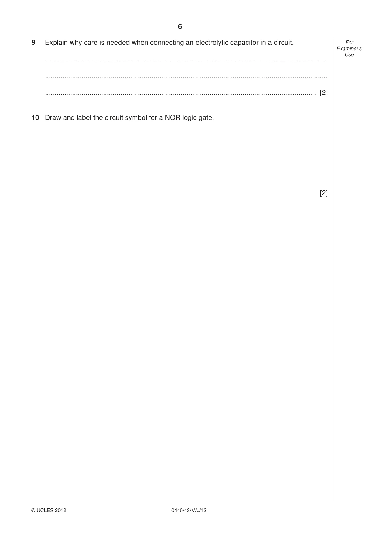
6 0445/43/M/J/12 © UCLES 2012 For Examiner’s Use 9 Explain why care is needed when connecting an electrolytic capacitor in a circuit. … … … [2] 10 Draw and label the circuit symbol for a NOR logic gate. [2]
Question paper, page 7
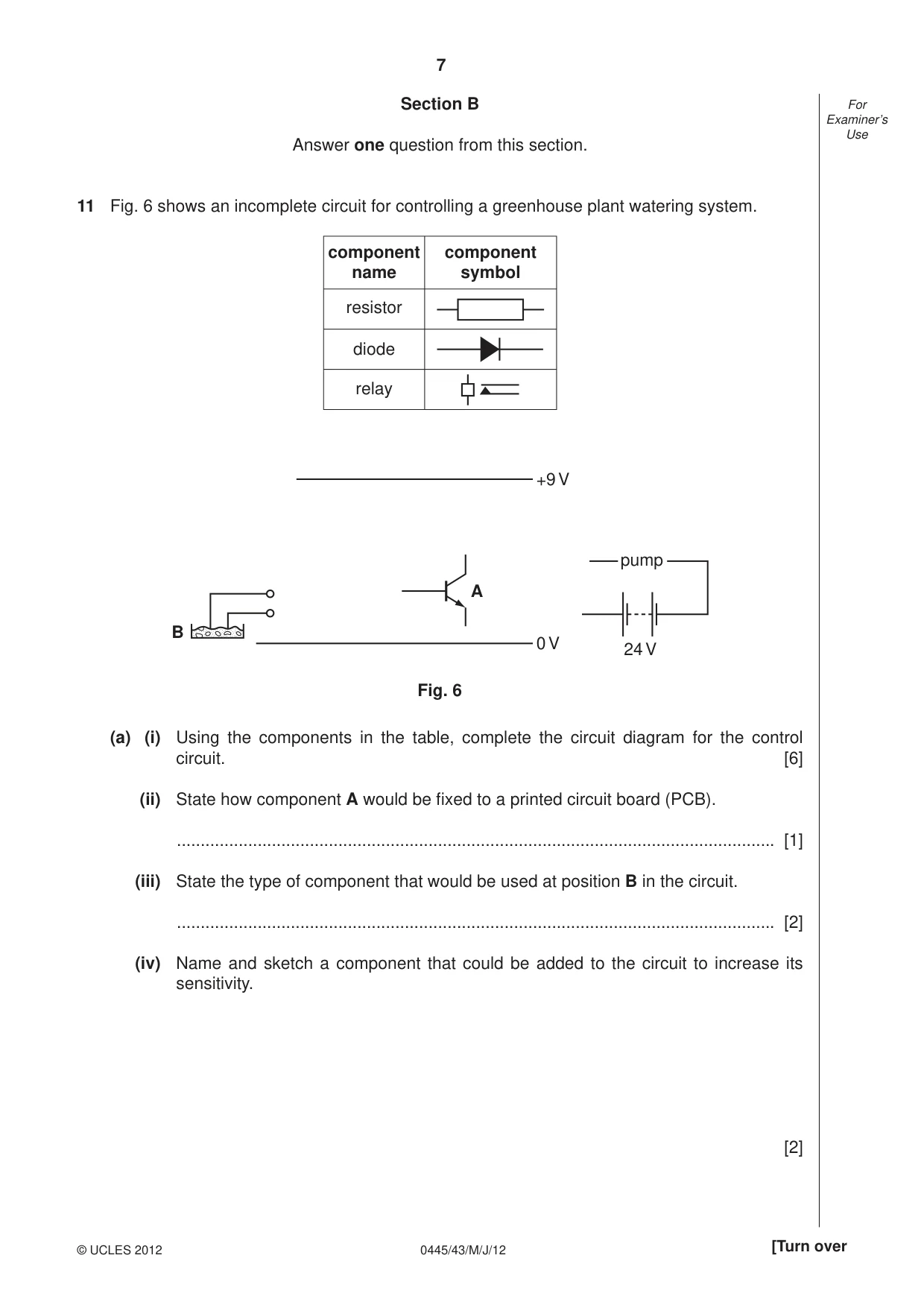
7 0445/43/M/J/12 © UCLES 2012 [Turn over For Examiner’s Use Section B Answer one question from this section. 11 Fig. 6 shows an incomplete circuit for controlling a greenhouse plant watering system. +9 V 0 V 24 V Fig. 6 A B pump component name resistor diode relay component symbol (a) (i) Using the components in the table, complete the circuit diagram for the control circuit. [6] (ii) State how component A would be fi xed to a printed circuit board (PCB). … [1] (iii) State the type of component that would be used at position B in the circuit. … [2] (iv) Name and sketch a component that could be added to the circuit to increase its sensitivity. [2]
Question paper, page 8
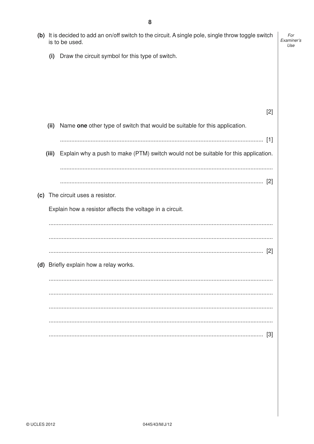
8 0445/43/M/J/12 © UCLES 2012 For Examiner’s Use (b) It is decided to add an on/off switch to the circuit. A single pole, single throw toggle switch is to be used. (i) Draw the circuit symbol for this type of switch. [2] (ii) Name one other type of switch that would be suitable for this application. … [1] (iii) Explain why a push to make (PTM) switch would not be suitable for this application. … … [2] (c) The circuit uses a resistor. Explain how a resistor affects the voltage in a circuit. … … … [2] (d) Briefl y explain how a relay works. … … … … … [3]
Question paper, page 9
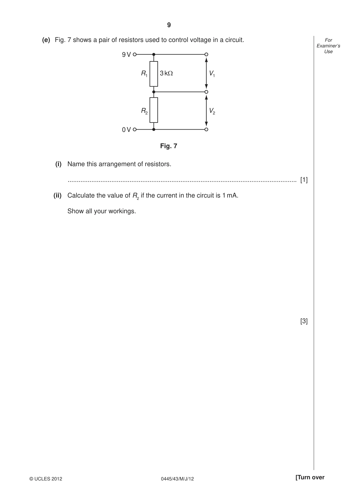
9 0445/43/M/J/12 © UCLES 2012 [Turn over For Examiner’s Use (e) Fig. 7 shows a pair of resistors used to control voltage in a circuit. V1 V2 R1 R2 3 kΩ 9 V 0 V Fig. 7 (i) Name this arrangement of resistors. … [1] (ii) Calculate the value of R2 if the current in the circuit is 1 mA. Show all your workings. [3]
Question paper, page 10
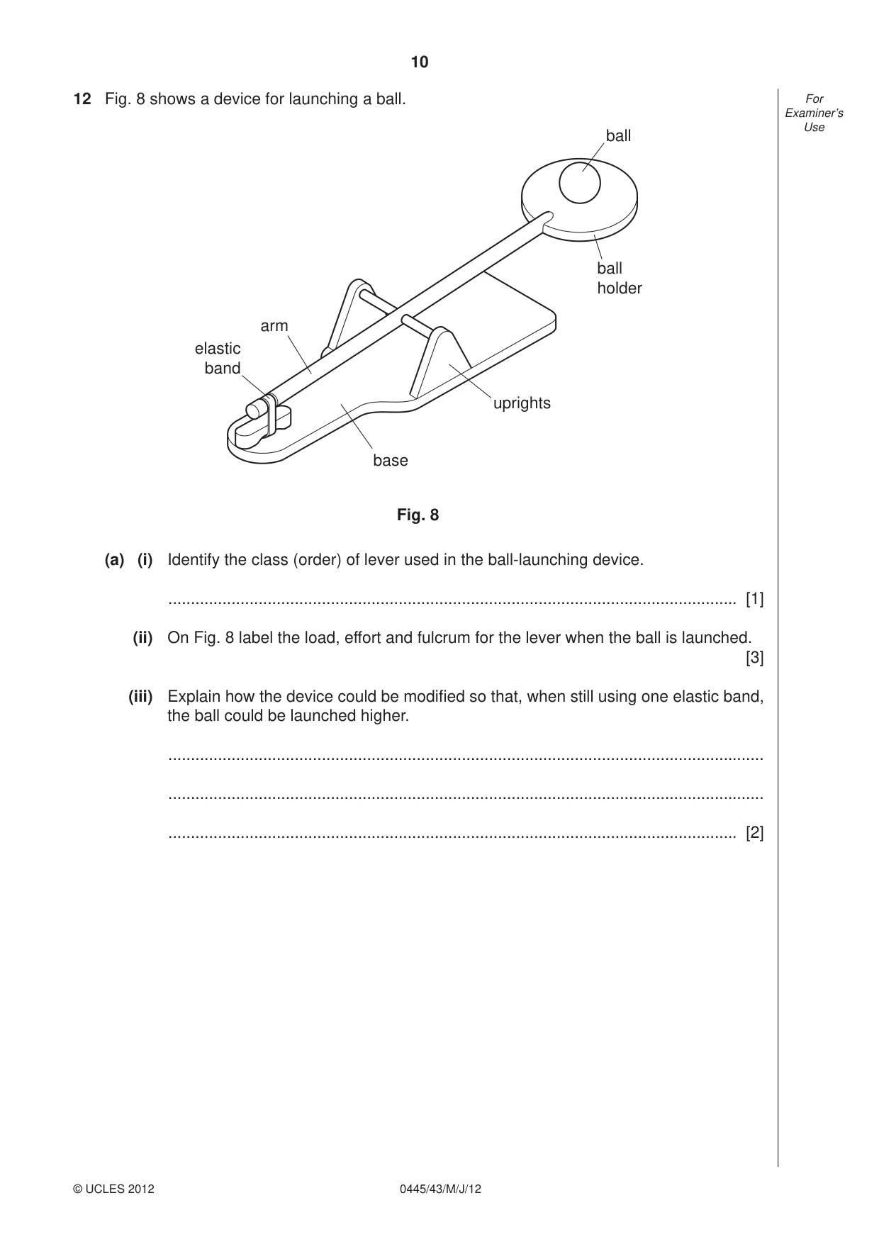
10 0445/43/M/J/12 © UCLES 2012 For Examiner’s Use 12 Fig. 8 shows a device for launching a ball. ball ball holder uprights base arm elastic band Fig. 8 (a) (i) Identify the class (order) of lever used in the ball-launching device. … [1] (ii) On Fig. 8 label the load, effort and fulcrum for the lever when the ball is launched. [3] (iii) Explain how the device could be modifi ed so that, when still using one elastic band, the ball could be launched higher. … … … [2]
Question paper, page 11
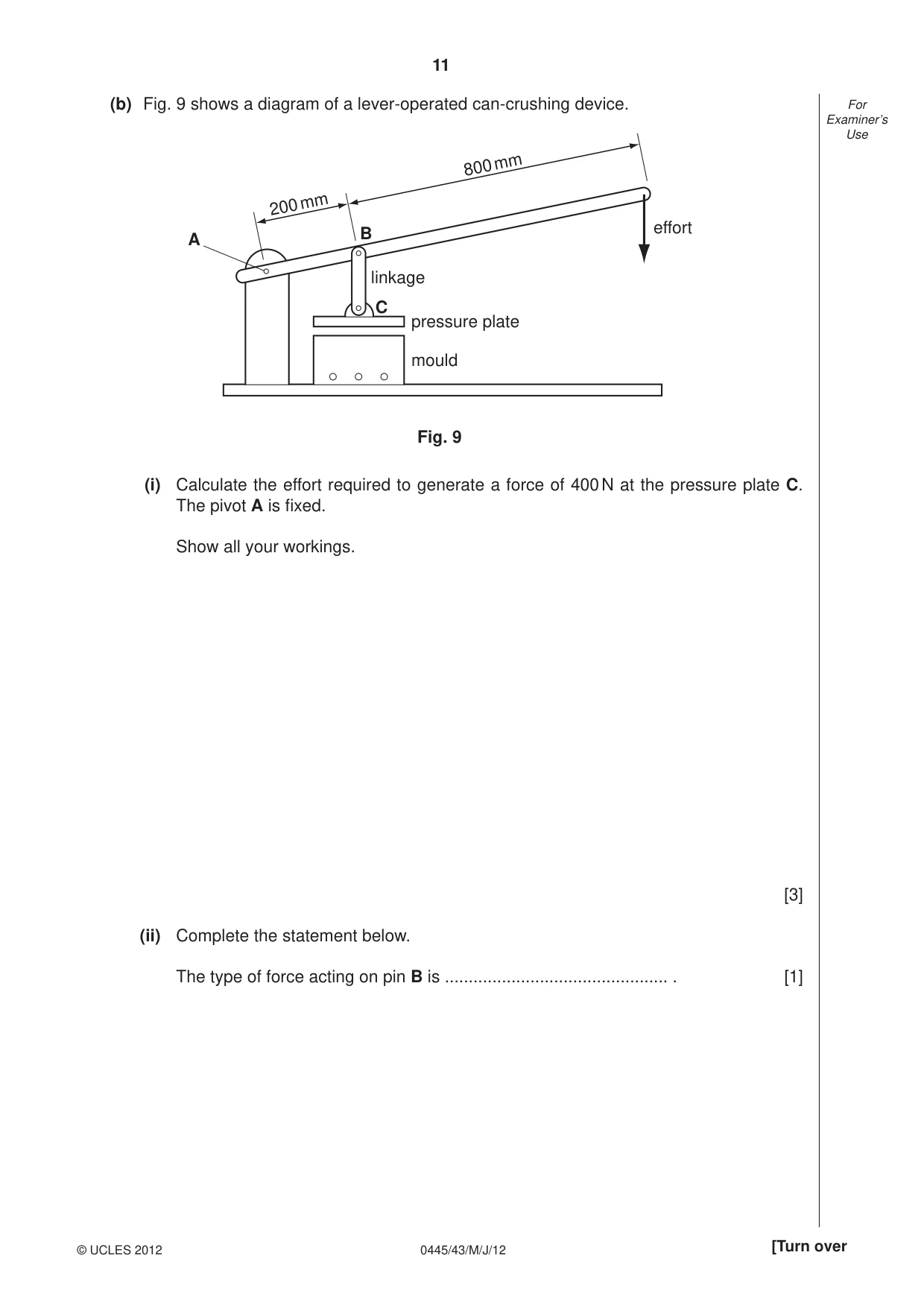
11 0445/43/M/J/12 © UCLES 2012 [Turn over For Examiner’s Use (b) Fig. 9 shows a diagram of a lever-operated can-crushing device. 800 mm 200 mm linkage pressure plate mould A B C Fig. 9 effort (i) Calculate the effort required to generate a force of 400 N at the pressure plate C. The pivot A is fi xed. Show all your workings. [3] (ii) Complete the statement below. The type of force acting on pin B is … . [1]
Question paper, page 12
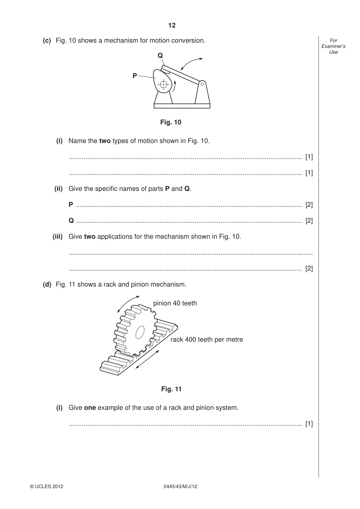
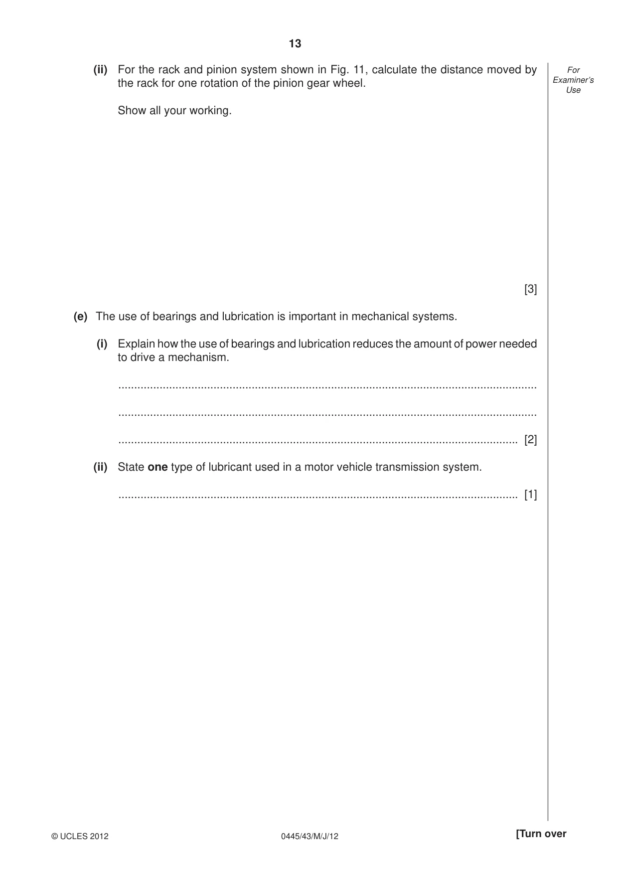
12 0445/43/M/J/12 © UCLES 2012 For Examiner’s Use (c) Fig. 10 shows a mechanism for motion conversion. Q P Fig. 10 (i) Name the two types of motion shown in Fig. 10. … [1] … [1] (ii) Give the specifi c names of parts P and Q. P … [2] Q … [2] (iii) Give two applications for the mechanism shown in Fig. 10. … … [2] (d) Fig. 11 shows a rack and pinion mechanism. pinion 40 teeth rack 400 teeth per metre Fig. 11 (i) Give one example of the use of a rack and pinion system. … [1]
Question paper, page 13
13 0445/43/M/J/12 © UCLES 2012 [Turn over For Examiner’s Use (ii) For the rack and pinion system shown in Fig. 11, calculate the distance moved by the rack for one rotation of the pinion gear wheel. Show all your working. [3] (e) The use of bearings and lubrication is important in mechanical systems. (i) Explain how the use of bearings and lubrication reduces the amount of power needed to drive a mechanism. … … … [2] (ii) State one type of lubricant used in a motor vehicle transmission system. … [1]
Question paper, page 14
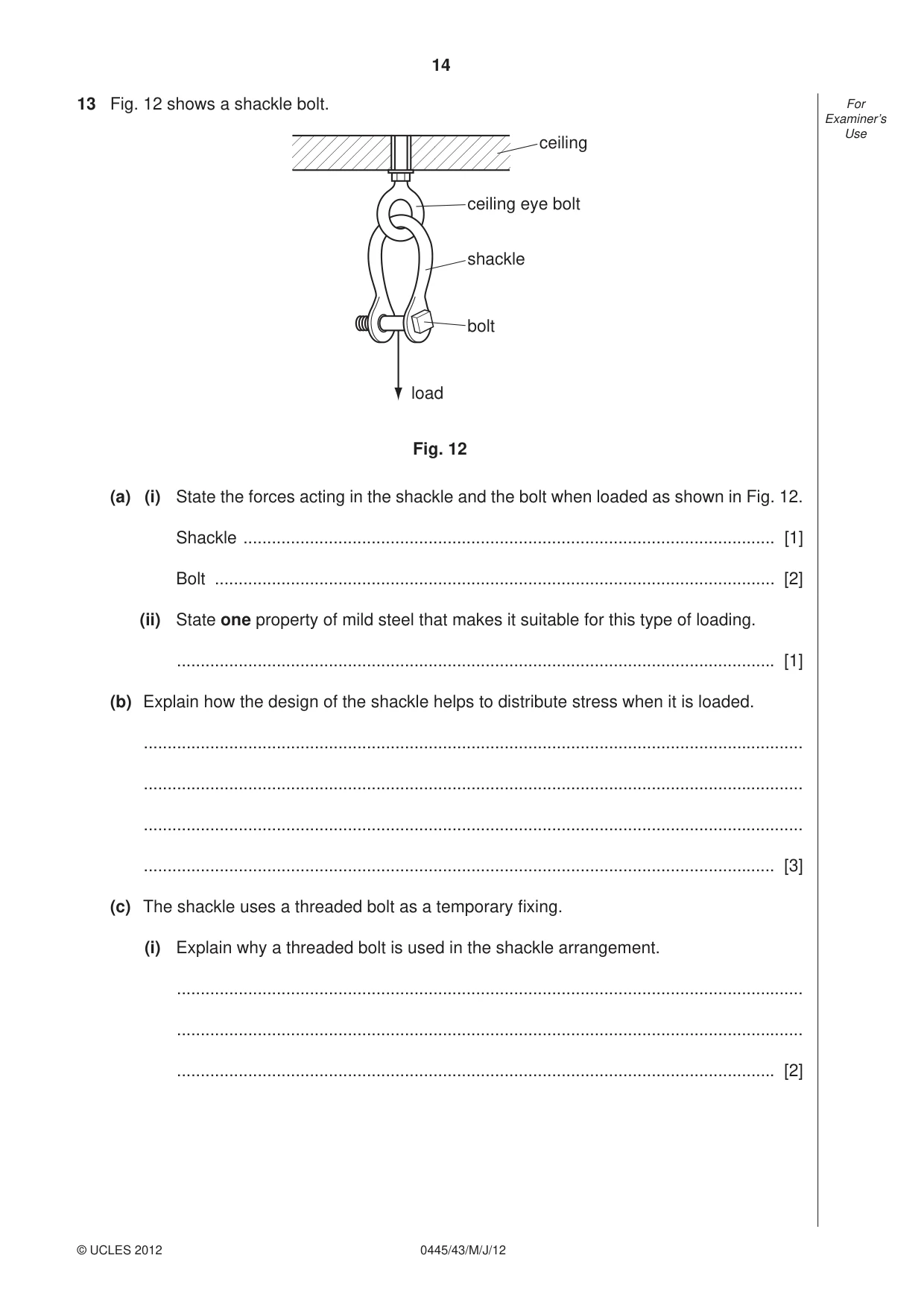
14 0445/43/M/J/12 © UCLES 2012 For Examiner’s Use 13 Fig. 12 shows a shackle bolt. bolt shackle ceiling eye bolt ceiling load Fig. 12 (a) (i) State the forces acting in the shackle and the bolt when loaded as shown in Fig. 12. Shackle … [1] Bolt … [2] (ii) State one property of mild steel that makes it suitable for this type of loading. … [1] (b) Explain how the design of the shackle helps to distribute stress when it is loaded. … … … … [3] (c) The shackle uses a threaded bolt as a temporary fi xing. (i) Explain why a threaded bolt is used in the shackle arrangement. … … … [2]
Question paper, page 15
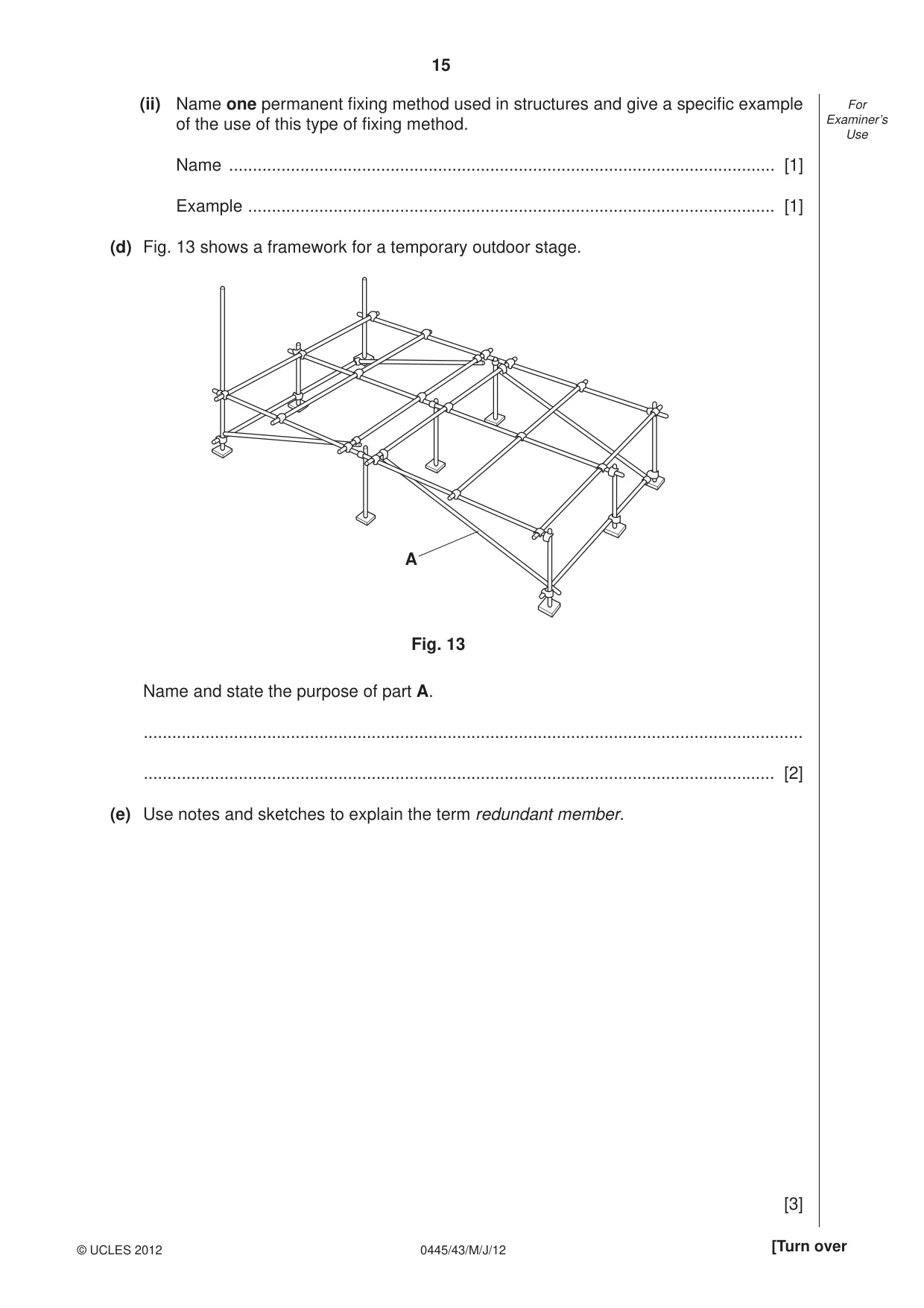
15 0445/43/M/J/12 © UCLES 2012 [Turn over For Examiner’s Use (ii) Name one permanent fi xing method used in structures and give a specifi c example of the use of this type of fi xing method. Name … [1] Example … [1] (d) Fig. 13 shows a framework for a temporary outdoor stage. A Fig. 13 Name and state the purpose of part A. … … [2] (e) Use notes and sketches to explain the term redundant member. [3]
Question paper, page 16
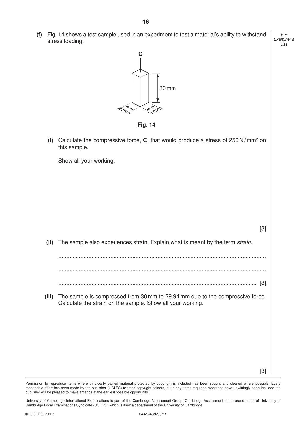
16 Permission to reproduce items where third-party owned material protected by copyright is included has been sought and cleared where possible. Every reasonable effort has been made by the publisher (UCLES) to trace copyright holders, but if any items requiring clearance have unwittingly been included the publisher will be pleased to make amends at the earliest possible opportunity. University of Cambridge International Examinations is part of the Cambridge Assessment Group. Cambridge Assessment is the brand name of University of Cambridge Local Examinations Syndicate (UCLES), which is itself a department of the University of Cambridge. 0445/43/M/J/12 © UCLES 2012 For Examiner’s Use (f) Fig. 14 shows a test sample used in an experiment to test a material’s ability to withstand stress loading. 30 mm 2 mm 2 mm C Fig. 14 (i) Calculate the compressive force, C, that would produce a stress of 250 N / mm2 on this sample. Show all your working. [3] (ii) The sample also experiences strain. Explain what is meant by the term strain. … … … [3] (iii) The sample is compressed from 30 mm to 29.94 mm due to the compressive force. Calculate the strain on the sample. Show all your working. [3]
Mark scheme, page 1
UNIVERSITY OF CAMBRIDGE INTERNATIONAL EXAMINATIONS International General Certificate of Secondary Education MARK SCHEME for the May/June 2012 question paper for the guidance of teachers 0445 DESIGN AND TECHNOLOGY 0445/43 Paper 4 (Systems and Control), maximum raw mark 50 This mark scheme is published as an aid to teachers and candidates, to indicate the requirements of the examination. It shows the basis on which Examiners were instructed to award marks. It does not indicate the details of the discussions that took place at an Examiners’ meeting before marking began, which would have considered the acceptability of alternative answers. Mark schemes must be read in conjunction with the question papers and the report on the examination. • Cambridge will not enter into discussions or correspondence in connection with these mark schemes. Cambridge is publishing the mark schemes for the May/June 2012 question papers for most IGCSE, GCE Advanced Level and Advanced Subsidiary Level syllabuses and some Ordinary Level syllabuses. www.XtremePapers.com
Mark scheme, page 2
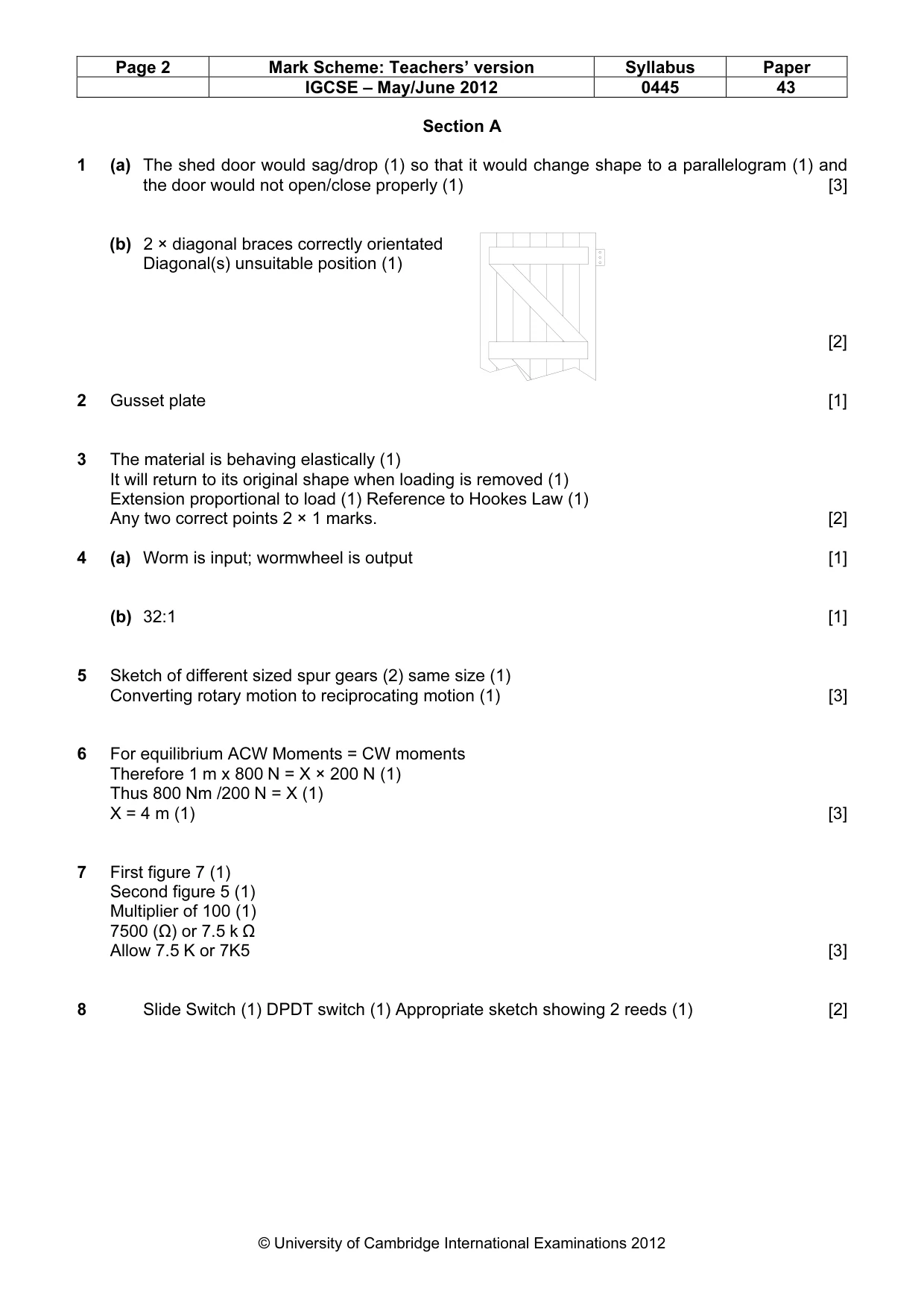
Page 2 Mark Scheme: Teachers’ version Syllabus Paper IGCSE – May/June 2012 0445 43 © University of Cambridge International Examinations 2012 Section A 1 (a) The shed door would sag/drop (1) so that it would change shape to a parallelogram (1) and the door would not open/close properly (1) [3] (b) 2 × diagonal braces correctly orientated Diagonal(s) unsuitable position (1) [2] 2 Gusset plate [1] 3 The material is behaving elastically (1) It will return to its original shape when loading is removed (1) Extension proportional to load (1) Reference to Hookes Law (1) Any two correct points 2 × 1 marks. [2] 4 (a) Worm is input; wormwheel is output [1] (b) 32:1 [1] 5 Sketch of different sized spur gears (2) same size (1) Converting rotary motion to reciprocating motion (1) [3] 6 For equilibrium ACW Moments = CW moments Therefore 1 m x 800 N = X × 200 N (1) Thus 800 Nm /200 N = X (1) X = 4 m (1) [3] 7 First figure 7 (1) Second figure 5 (1) Multiplier of 100 (1) 7500 (Ω) or 7.5 k Ω Allow 7.5 K or 7K5 [3] 8 Slide Switch (1) DPDT switch (1) Appropriate sketch showing 2 reeds (1) [2]
Mark scheme, page 3
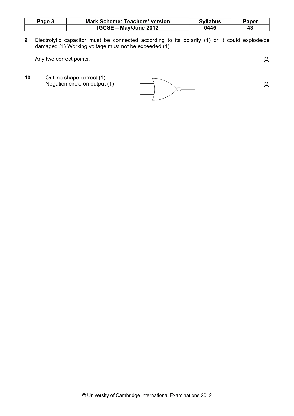
Page 3 Mark Scheme: Teachers’ version Syllabus Paper IGCSE – May/June 2012 0445 43 © University of Cambridge International Examinations 2012 9 Electrolytic capacitor must be connected according to its polarity (1) or it could explode/be damaged (1) Working voltage must not be exceeded (1). Any two correct points. [2] 10 Outline shape correct (1) Negation circle on output (1) [2]
Mark scheme, page 4
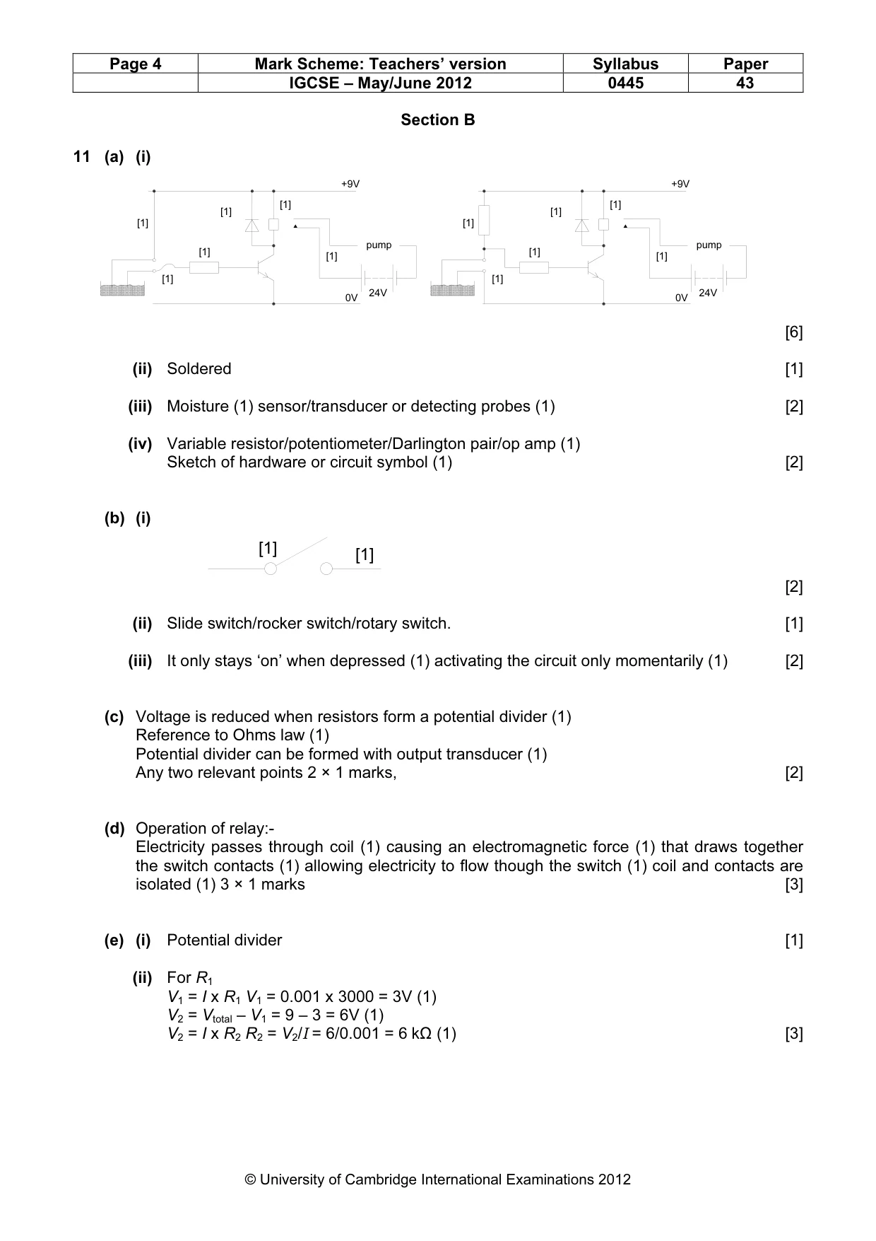
Page 4 Mark Scheme: Teachers’ version Syllabus Paper IGCSE – May/June 2012 0445 43 © University of Cambridge International Examinations 2012 Section B 11 (a) (i) [6] (ii) Soldered [1] (iii) Moisture (1) sensor/transducer or detecting probes (1) [2] (iv) Variable resistor/potentiometer/Darlington pair/op amp (1) Sketch of hardware or circuit symbol (1) [2] (b) (i) [2] (ii) Slide switch/rocker switch/rotary switch. [1] (iii) It only stays ‘on’ when depressed (1) activating the circuit only momentarily (1) [2] (c) Voltage is reduced when resistors form a potential divider (1) Reference to Ohms law (1) Potential divider can be formed with output transducer (1) Any two relevant points 2 × 1 marks, [2] (d) Operation of relay:- Electricity passes through coil (1) causing an electromagnetic force (1) that draws together the switch contacts (1) allowing electricity to flow though the switch (1) coil and contacts are isolated (1) 3 × 1 marks [3] (e) (i) Potential divider [1] (ii) For R1 V1 = I x R1 V1 = 0.001 x 3000 = 3V (1) V2 = Vtotal – V1 = 9 – 3 = 6V (1) V2 = I x R2 R2 = V2/I = 6/0.001 = 6 kΩ (1) [3] 24V pump [1] [1] [1] [1] [1] [1] +9V 0V 24V pump [1] [1] [1] [1] [1] [1] +9V 0V [1] [1]
Mark scheme, page 5
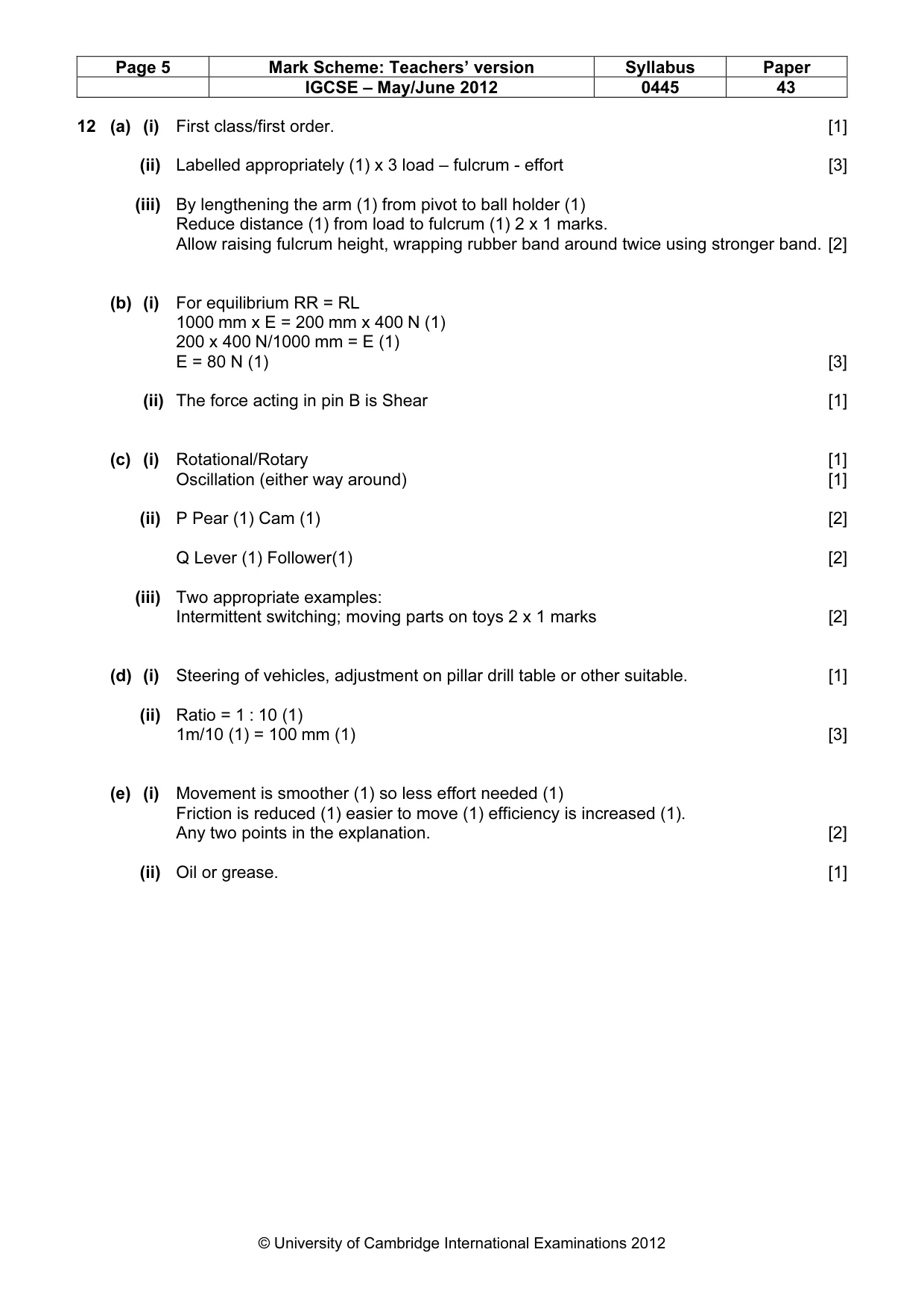
Page 5 Mark Scheme: Teachers’ version Syllabus Paper IGCSE – May/June 2012 0445 43 © University of Cambridge International Examinations 2012 12 (a) (i) First class/first order. [1] (ii) Labelled appropriately (1) x 3 load – fulcrum - effort [3] (iii) By lengthening the arm (1) from pivot to ball holder (1) Reduce distance (1) from load to fulcrum (1) 2 x 1 marks. Allow raising fulcrum height, wrapping rubber band around twice using stronger band. [2] (b) (i) For equilibrium RR = RL 1000 mm x E = 200 mm x 400 N (1) 200 x 400 N/1000 mm = E (1) E = 80 N (1) [3] (ii) The force acting in pin B is Shear [1] (c) (i) Rotational/Rotary [1] Oscillation (either way around) [1] (ii) P Pear (1) Cam (1) [2] Q Lever (1) Follower(1) [2] (iii) Two appropriate examples: Intermittent switching; moving parts on toys 2 x 1 marks [2] (d) (i) Steering of vehicles, adjustment on pillar drill table or other suitable. [1] (ii) Ratio = 1 : 10 (1) 1m/10 (1) = 100 mm (1) [3] (e) (i) Movement is smoother (1) so less effort needed (1) Friction is reduced (1) easier to move (1) efficiency is increased (1). Any two points in the explanation. [2] (ii) Oil or grease. [1]
Mark scheme, page 6
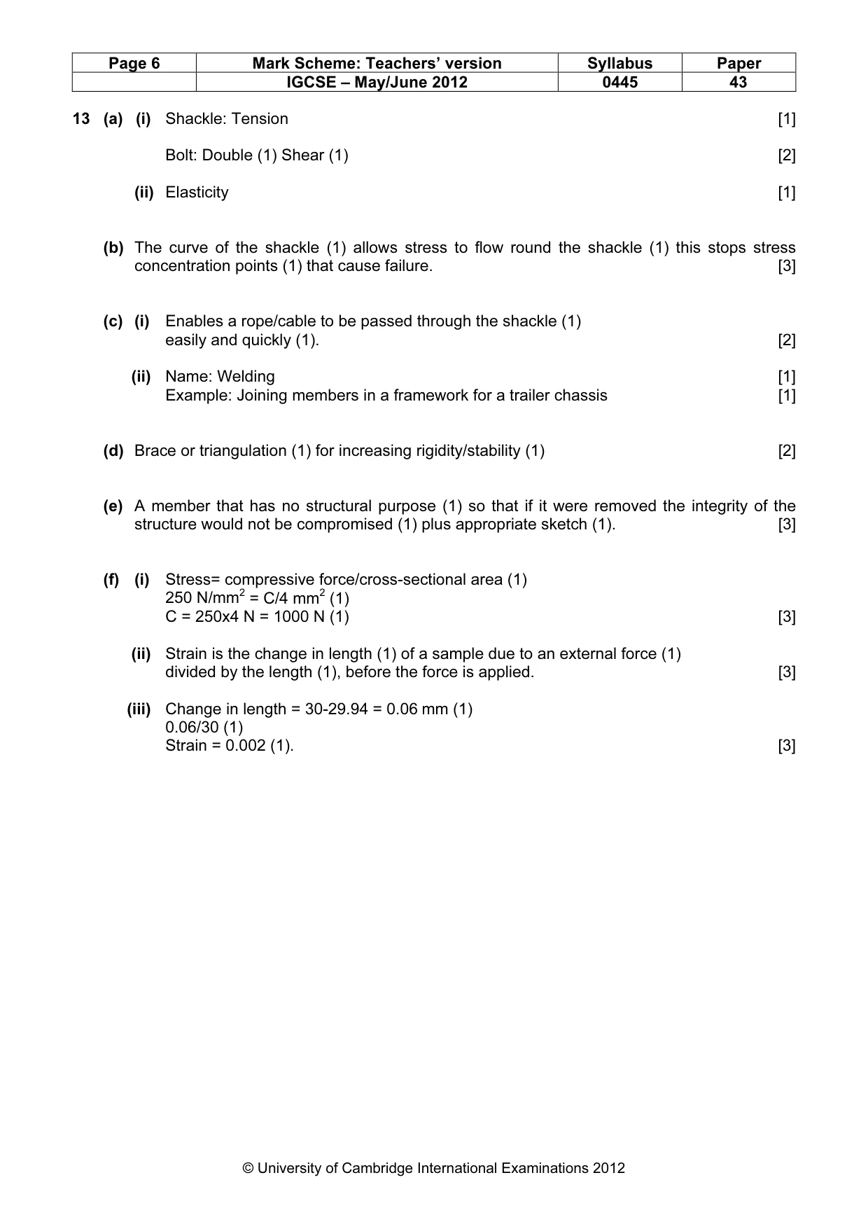
Page 6 Mark Scheme: Teachers’ version Syllabus Paper IGCSE – May/June 2012 0445 43 © University of Cambridge International Examinations 2012 13 (a) (i) Shackle: Tension [1] Bolt: Double (1) Shear (1) [2] (ii) Elasticity [1] (b) The curve of the shackle (1) allows stress to flow round the shackle (1) this stops stress concentration points (1) that cause failure. [3] (c) (i) Enables a rope/cable to be passed through the shackle (1) easily and quickly (1). [2] (ii) Name: Welding [1] Example: Joining members in a framework for a trailer chassis [1] (d) Brace or triangulation (1) for increasing rigidity/stability (1) [2] (e) A member that has no structural purpose (1) so that if it were removed the integrity of the structure would not be compromised (1) plus appropriate sketch (1). [3] (f) (i) Stress= compressive force/cross-sectional area (1) 250 N/mm2 = C/4 mm2 (1) C = 250x4 N = 1000 N (1) [3] (ii) Strain is the change in length (1) of a sample due to an external force (1) divided by the length (1), before the force is applied. [3] (iii) Change in length = 30-29.94 = 0.06 mm (1) 0.06/30 (1) Strain = 0.002 (1). [3]
What you needed in this session
Cambridge’s own grade thresholds for 2012 May/June, Paper 4 · Variant 3. A higher threshold means an easier paper — the bar moves with how the cohort did.