Cambridge IGCSE Design and Technology 0445 — 2011 Oct/Nov Paper 4 · Variant 1
0445/41/O/N/11
The question paper and its mark scheme, free to read here and free to download. This is Cambridge’s own paper, exactly as it was sat.
Question paper16 pages

Mark scheme7 pages
Answers below. Sit the paper first if you are practising.
Paper as text
Question paper, page 1
[Turn over *5793240403* READ THESE INSTRUCTIONS FIRST Write your Centre number, candidate number and name on all the work you hand in. Write in dark blue or black pen. You may use a soft pencil for any diagrams or graphs. Do not use staples, paper clips, highlighters, glue or correction fl uid. DO NOT WRITE IN ANY BARCODES. You may use a calculator. Section A Answer all questions. Section B Answer one question. At the end of the examination, fasten all your work securely together. The number of marks is given in brackets [ ] at the end of each question or part question. For Examiner’s Use Section A Section B Total DESIGN AND TECHNOLOGY 0445/41 Paper 4 Systems and Control October/November 2011 1 hour Candidates answer on the Question Paper. No Additional Materials are required. To be taken together with Paper 1 in one session of 2 hours and 15 minutes. UNIVERSITY OF CAMBRIDGE INTERNATIONAL EXAMINATIONS International General Certifi cate of Secondary Education This document consists of 15 printed pages and 1 blank page. [Turn over IB11 11_0445_41/2RP © UCLES 2011 www.XtremePapers.com
Question paper, page 2
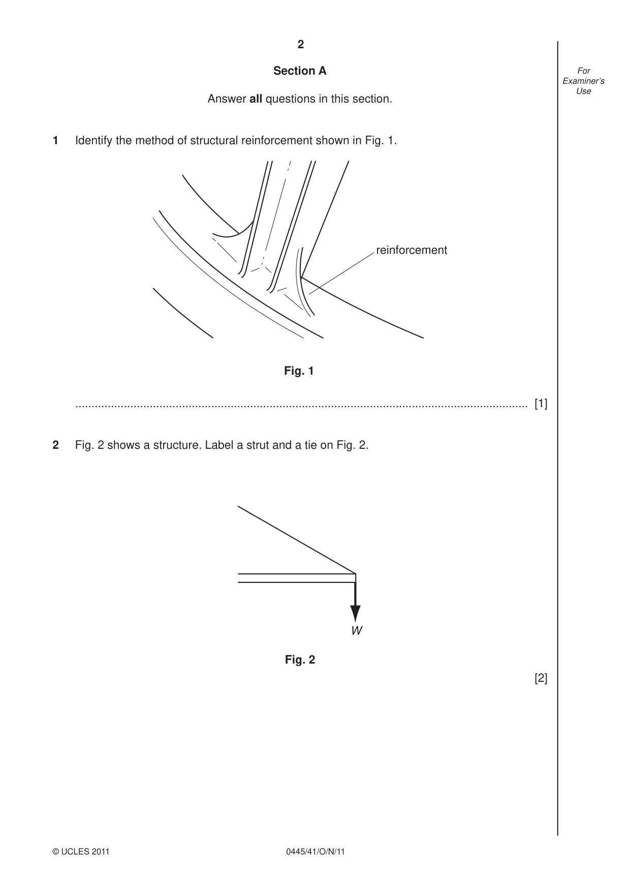
2 0445/41/O/N/11 © UCLES 2011 For Examiner’s Use Section A Answer all questions in this section. 1 Identify the method of structural reinforcement shown in Fig. 1. reinforcement Fig. 1 … [1] 2 Fig. 2 shows a structure. Label a strut and a tie on Fig. 2. W Fig. 2 [2]
Question paper, page 3
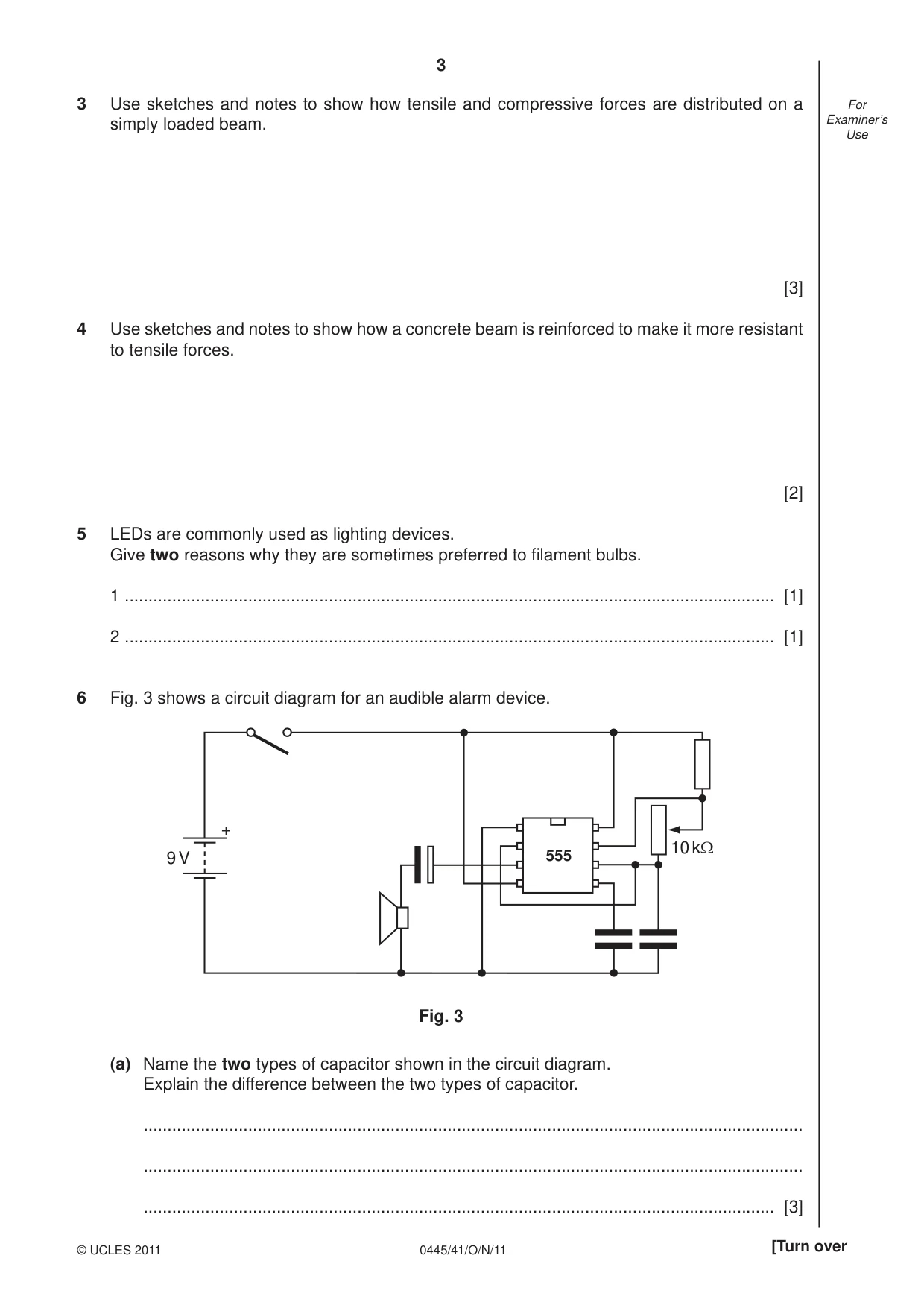
3 0445/41/O/N/11 © UCLES 2011 [Turn over For Examiner’s Use 3 Use sketches and notes to show how tensile and compressive forces are distributed on a simply loaded beam. [3] 4 Use sketches and notes to show how a concrete beam is reinforced to make it more resistant to tensile forces. [2] 5 LEDs are commonly used as lighting devices. Give two reasons why they are sometimes preferred to fi lament bulbs. 1 … [1] 2 … [1] 6 Fig. 3 shows a circuit diagram for an audible alarm device. + 9 V 10 kΩ 555 Fig. 3 (a) Name the two types of capacitor shown in the circuit diagram. Explain the difference between the two types of capacitor. … … … [3]
Question paper, page 4
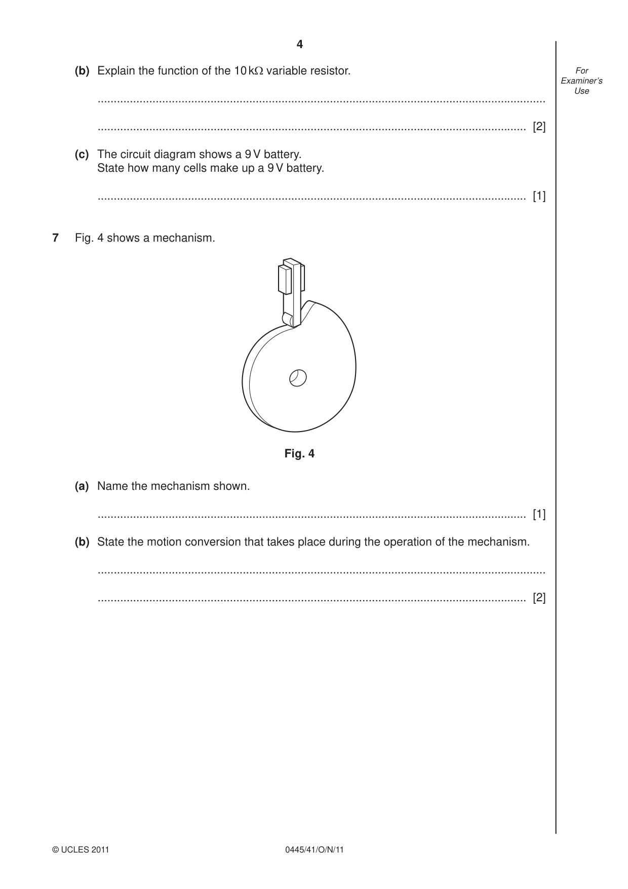
4 0445/41/O/N/11 © UCLES 2011 For Examiner’s Use (b) Explain the function of the 10 kΩ variable resistor. … … [2] (c) The circuit diagram shows a 9 V battery. State how many cells make up a 9 V battery. … [1] 7 Fig. 4 shows a mechanism. Fig. 4 (a) Name the mechanism shown. … [1] (b) State the motion conversion that takes place during the operation of the mechanism. … … [2]
Question paper, page 5
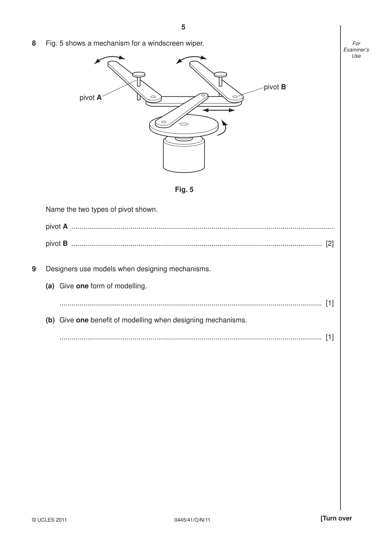
5 0445/41/O/N/11 © UCLES 2011 [Turn over For Examiner’s Use 8 Fig. 5 shows a mechanism for a windscreen wiper. pivot A pivot B Fig. 5 Name the two types of pivot shown. pivot A … pivot B … [2] 9 Designers use models when designing mechanisms. (a) Give one form of modelling. … [1] (b) Give one benefi t of modelling when designing mechanisms. … [1]
Question paper, page 6
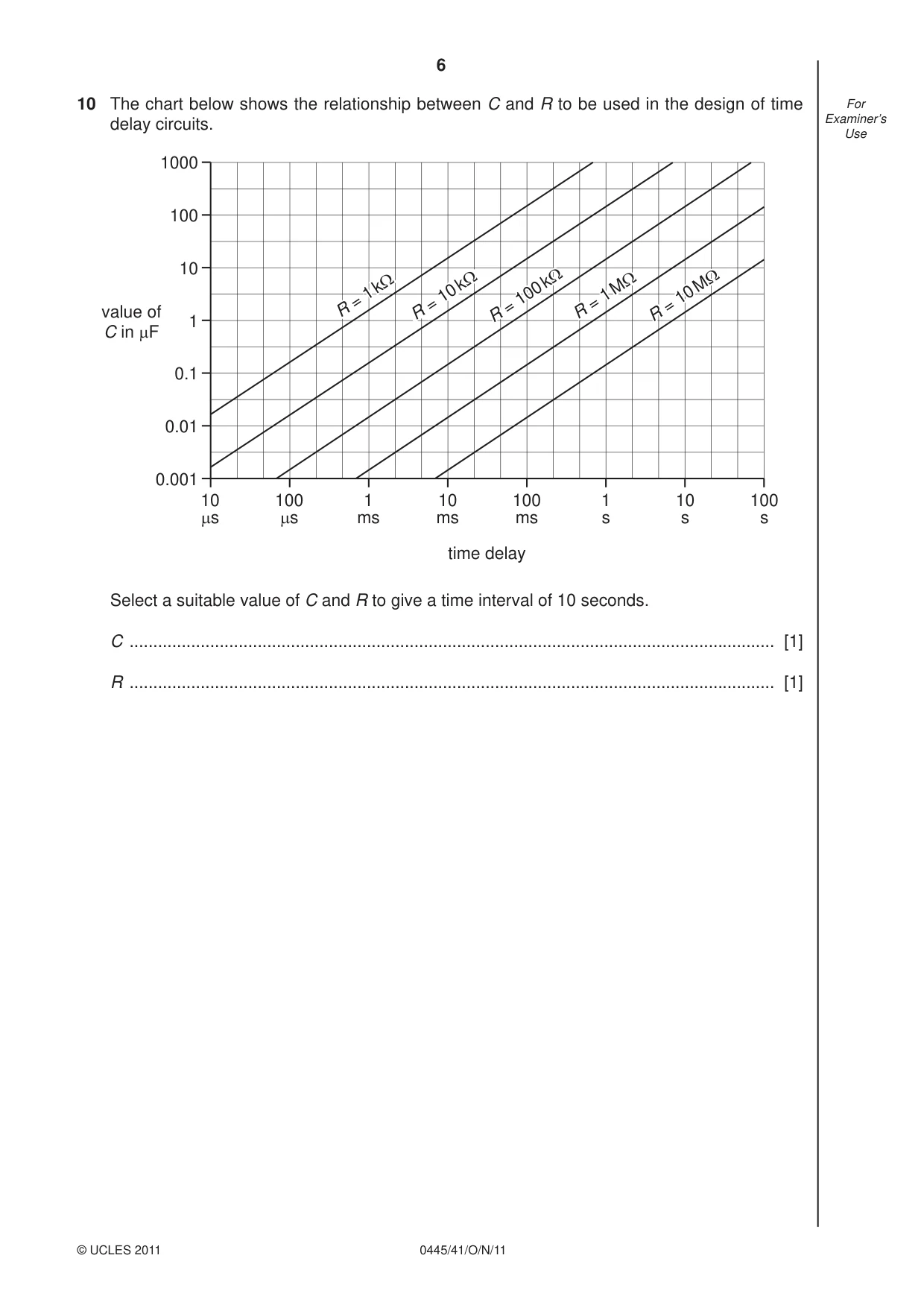
6 0445/41/O/N/11 © UCLES 2011 For Examiner’s Use 10 The chart below shows the relationship between C and R to be used in the design of time delay circuits. 1000 100 10 1 0.1 0.01 0.001 10 µs 100 µs 1 ms 10 ms 100 ms 1 s 10 s 100 s value of C in µF time delay R = 1 = 1 kΩ R1 = 10 = 10 kΩ R = 100 = 100 kΩ R = 1 = 1 MΩ R = 10 = 10 MΩ R = 1 kΩ R = 10 kΩ R = 100 kΩ R = 1 MΩ R = 10 MΩ Select a suitable value of C and R to give a time interval of 10 seconds. C … [1] R … [1]
Question paper, page 7
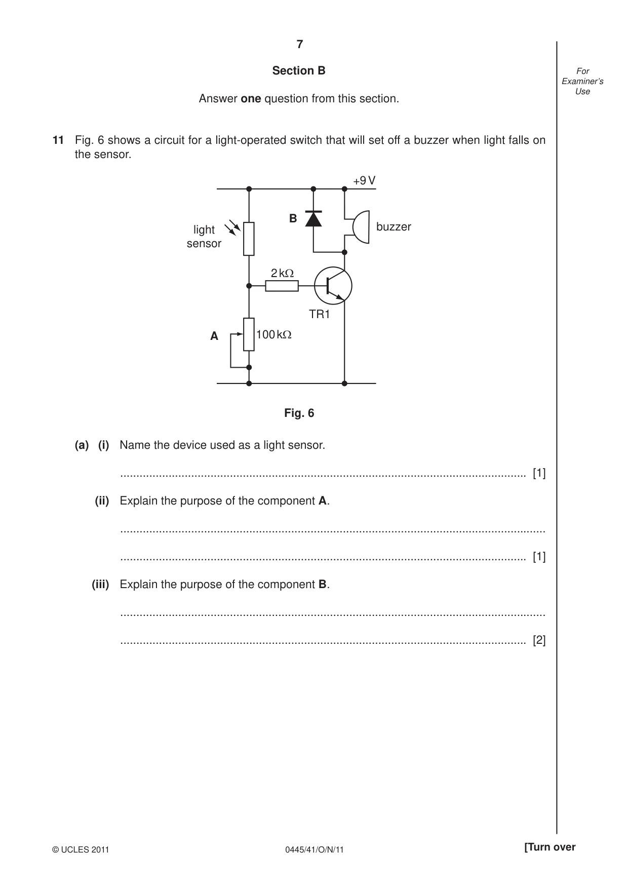
7 0445/41/O/N/11 © UCLES 2011 [Turn over For Examiner’s Use Section B Answer one question from this section. 11 Fig. 6 shows a circuit for a light-operated switch that will set off a buzzer when light falls on the sensor. 2 kΩ 100 kΩ A B light sensor TR1 +9 V buzzer Fig. 6 (a) (i) Name the device used as a light sensor. … [1] (ii) Explain the purpose of the component A. … … [1] (iii) Explain the purpose of the component B. … … [2]
Question paper, page 8
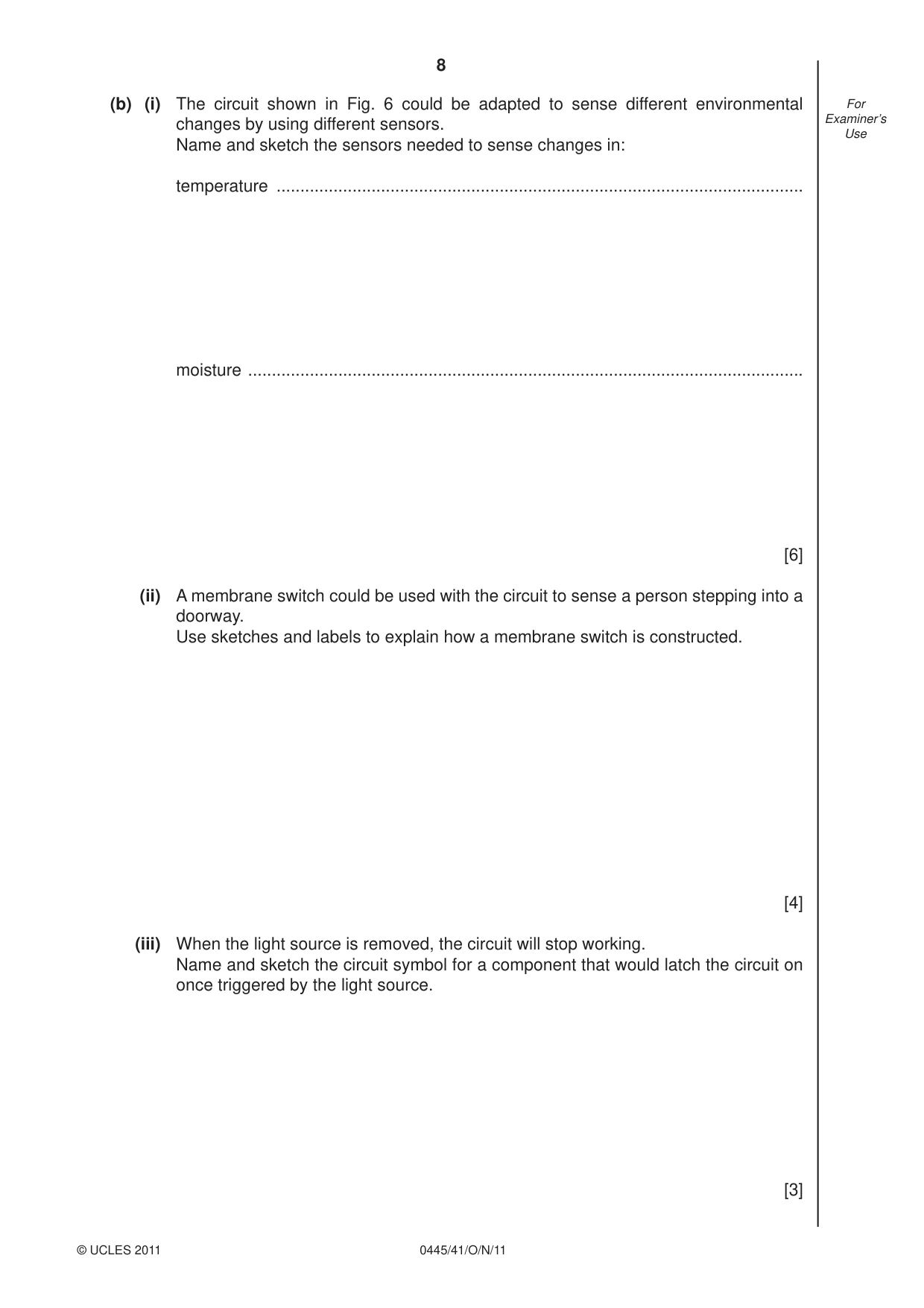
8 0445/41/O/N/11 © UCLES 2011 For Examiner’s Use (b) (i) The circuit shown in Fig. 6 could be adapted to sense different environmental changes by using different sensors. Name and sketch the sensors needed to sense changes in: temperature … moisture … [6] (ii) A membrane switch could be used with the circuit to sense a person stepping into a doorway. Use sketches and labels to explain how a membrane switch is constructed. [4] (iii) When the light source is removed, the circuit will stop working. Name and sketch the circuit symbol for a component that would latch the circuit on once triggered by the light source. [3]
Question paper, page 9
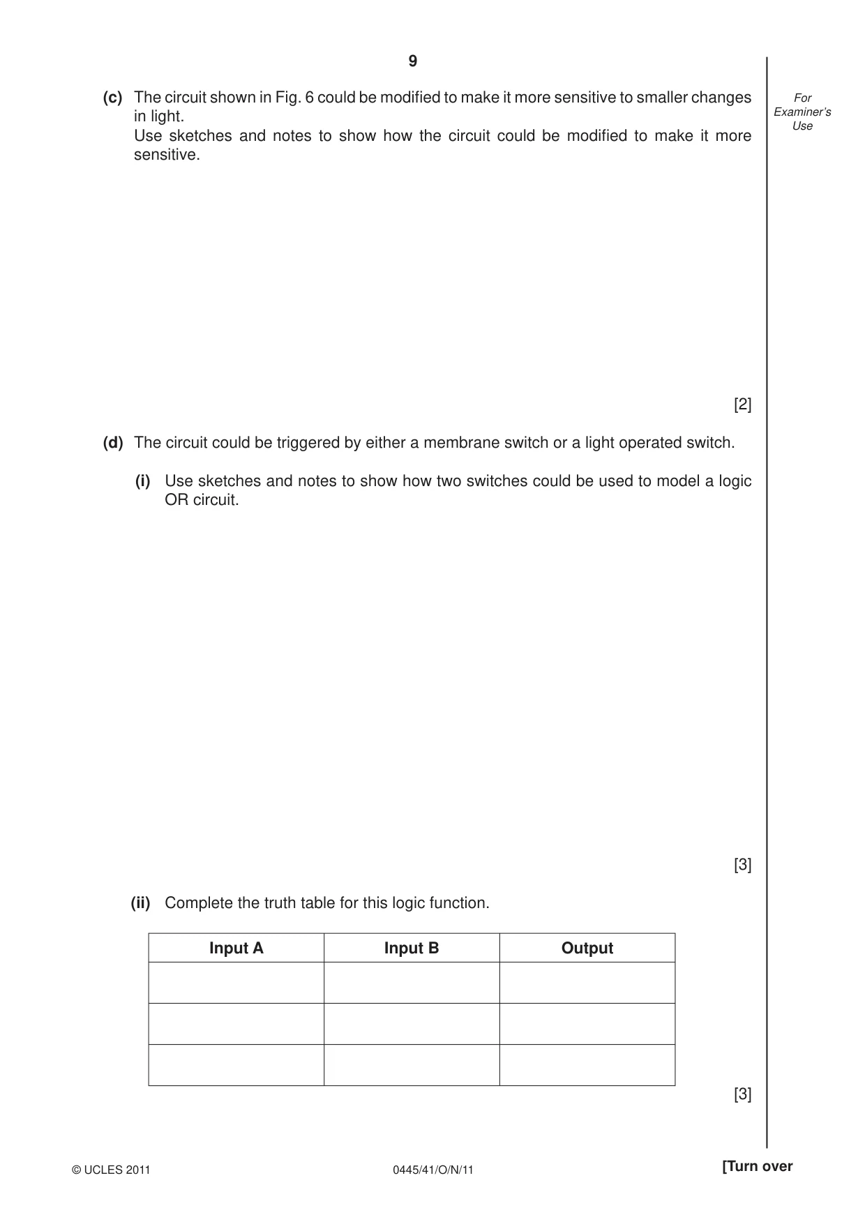
9 0445/41/O/N/11 © UCLES 2011 [Turn over For Examiner’s Use (c) The circuit shown in Fig. 6 could be modifi ed to make it more sensitive to smaller changes in light. Use sketches and notes to show how the circuit could be modifi ed to make it more sensitive. [2] (d) The circuit could be triggered by either a membrane switch or a light operated switch. (i) Use sketches and notes to show how two switches could be used to model a logic OR circuit. [3] (ii) Complete the truth table for this logic function. Input A Input B Output [3]
Question paper, page 10
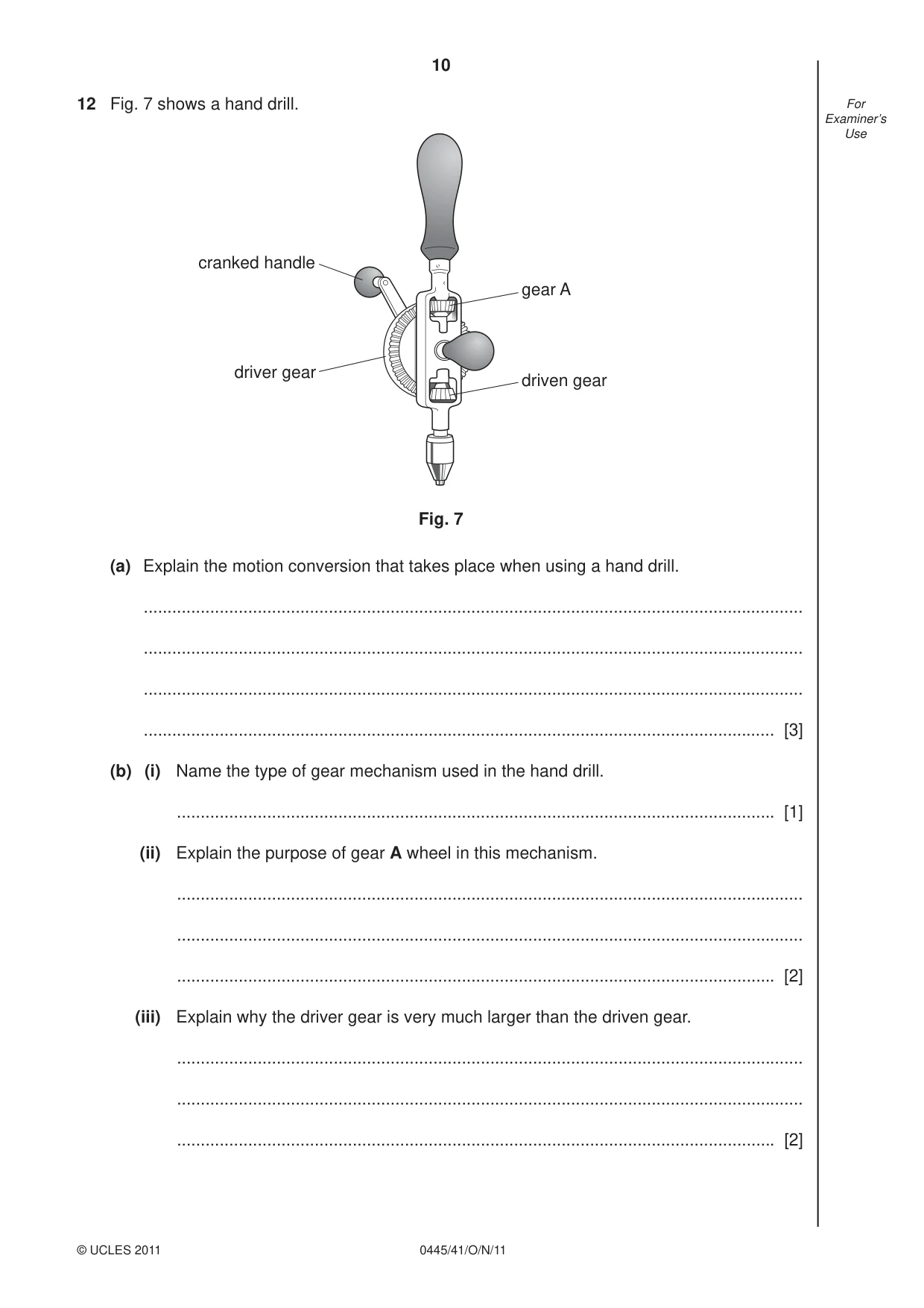
10 0445/41/O/N/11 © UCLES 2011 For Examiner’s Use 12 Fig. 7 shows a hand drill. gear A driven gear cranked handle driver gear Fig. 7 (a) Explain the motion conversion that takes place when using a hand drill. … … … … [3] (b) (i) Name the type of gear mechanism used in the hand drill. … [1] (ii) Explain the purpose of gear A wheel in this mechanism. … … … [2] (iii) Explain why the driver gear is very much larger than the driven gear. … … … [2]
Question paper, page 11
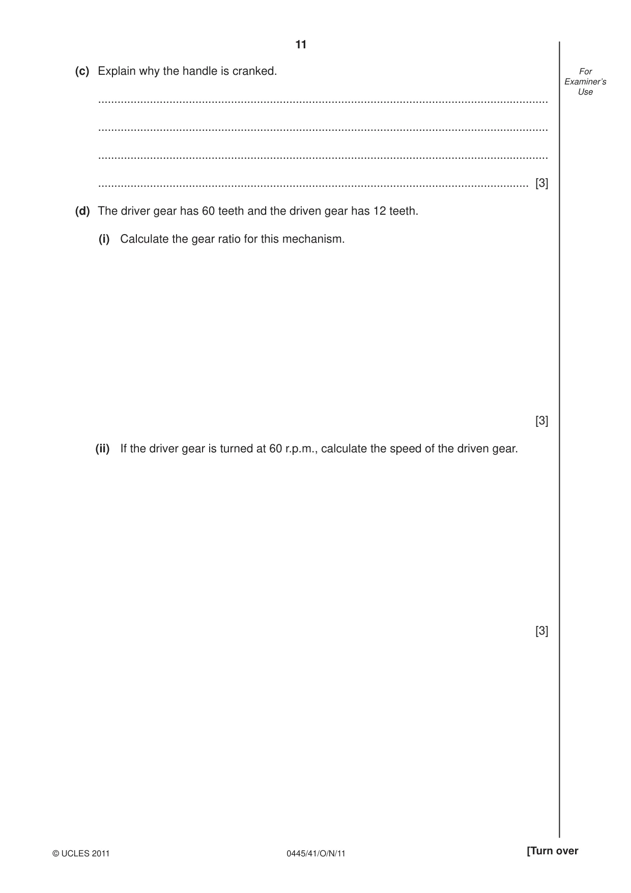
11 0445/41/O/N/11 © UCLES 2011 [Turn over For Examiner’s Use (c) Explain why the handle is cranked. … … … … [3] (d) The driver gear has 60 teeth and the driven gear has 12 teeth. (i) Calculate the gear ratio for this mechanism. [3] (ii) If the driver gear is turned at 60 r.p.m., calculate the speed of the driven gear. [3]
Question paper, page 12
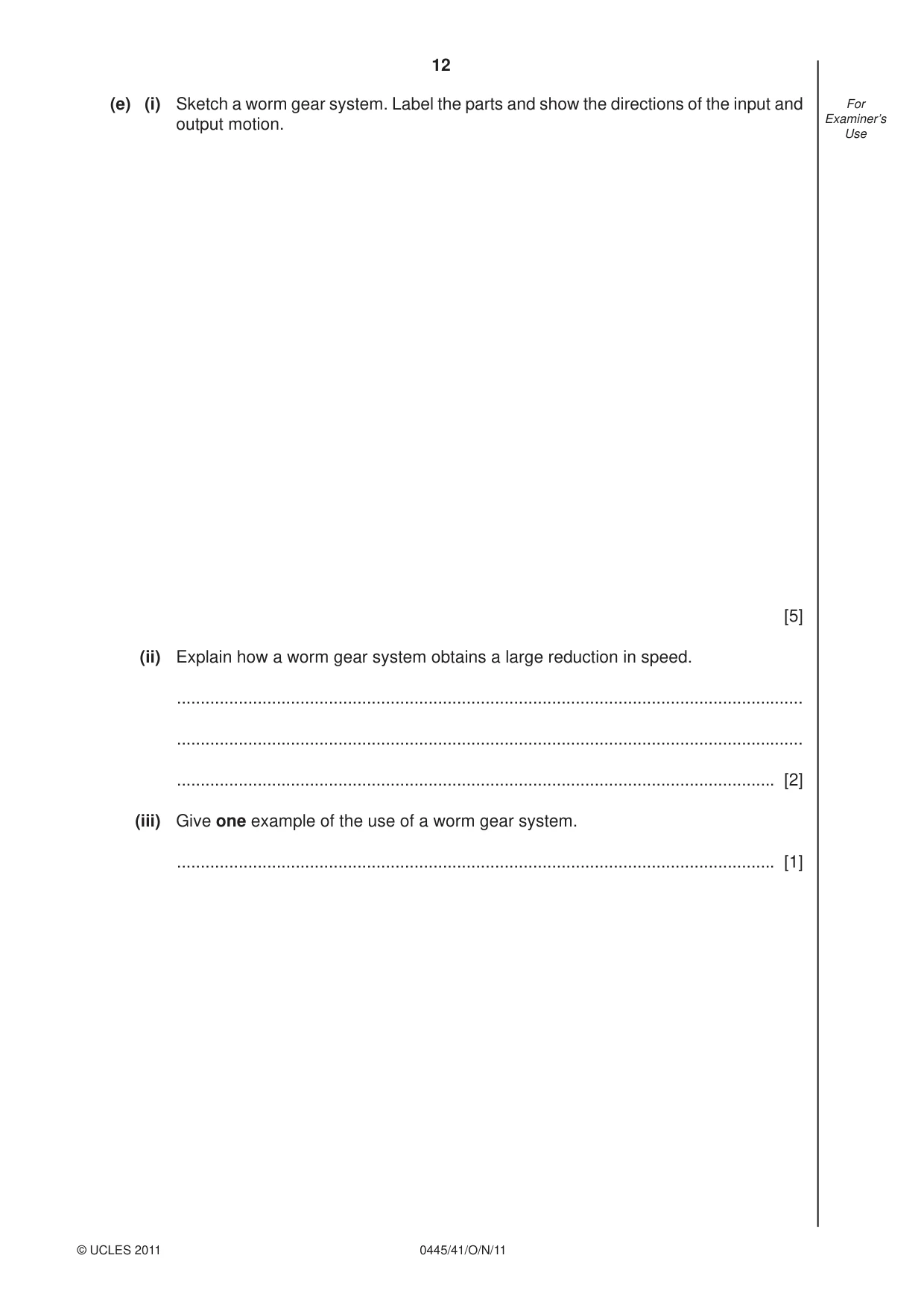
12 0445/41/O/N/11 © UCLES 2011 For Examiner’s Use (e) (i) Sketch a worm gear system. Label the parts and show the directions of the input and output motion. [5] (ii) Explain how a worm gear system obtains a large reduction in speed. … … … [2] (iii) Give one example of the use of a worm gear system. … [1]
Question paper, page 13
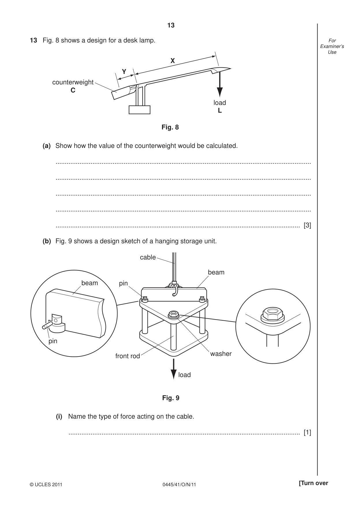
13 0445/41/O/N/11 © UCLES 2011 [Turn over For Examiner’s Use 13 Fig. 8 shows a design for a desk lamp. counterweight C load L X Y Fig. 8 (a) Show how the value of the counterweight would be calculated. … … … … … [3] (b) Fig. 9 shows a design sketch of a hanging storage unit. pin beam cable pin beam front rod washer load Fig. 9 (i) Name the type of force acting on the cable. … [1]
Question paper, page 14
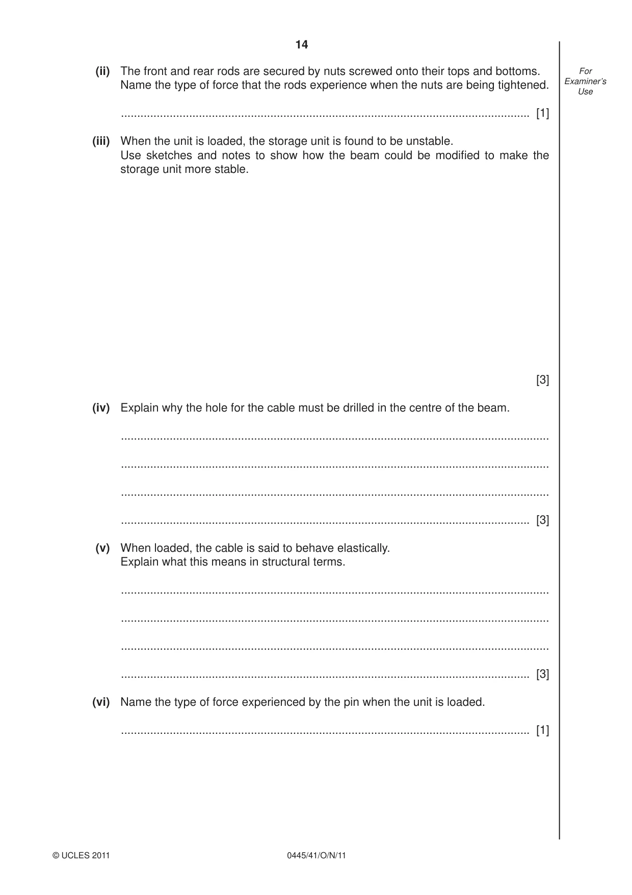
14 0445/41/O/N/11 © UCLES 2011 For Examiner’s Use (ii) The front and rear rods are secured by nuts screwed onto their tops and bottoms. Name the type of force that the rods experience when the nuts are being tightened. … [1] (iii) When the unit is loaded, the storage unit is found to be unstable. Use sketches and notes to show how the beam could be modifi ed to make the storage unit more stable. [3] (iv) Explain why the hole for the cable must be drilled in the centre of the beam. … … … … [3] (v) When loaded, the cable is said to behave elastically. Explain what this means in structural terms. … … … … [3] (vi) Name the type of force experienced by the pin when the unit is loaded. … [1]
Question paper, page 15
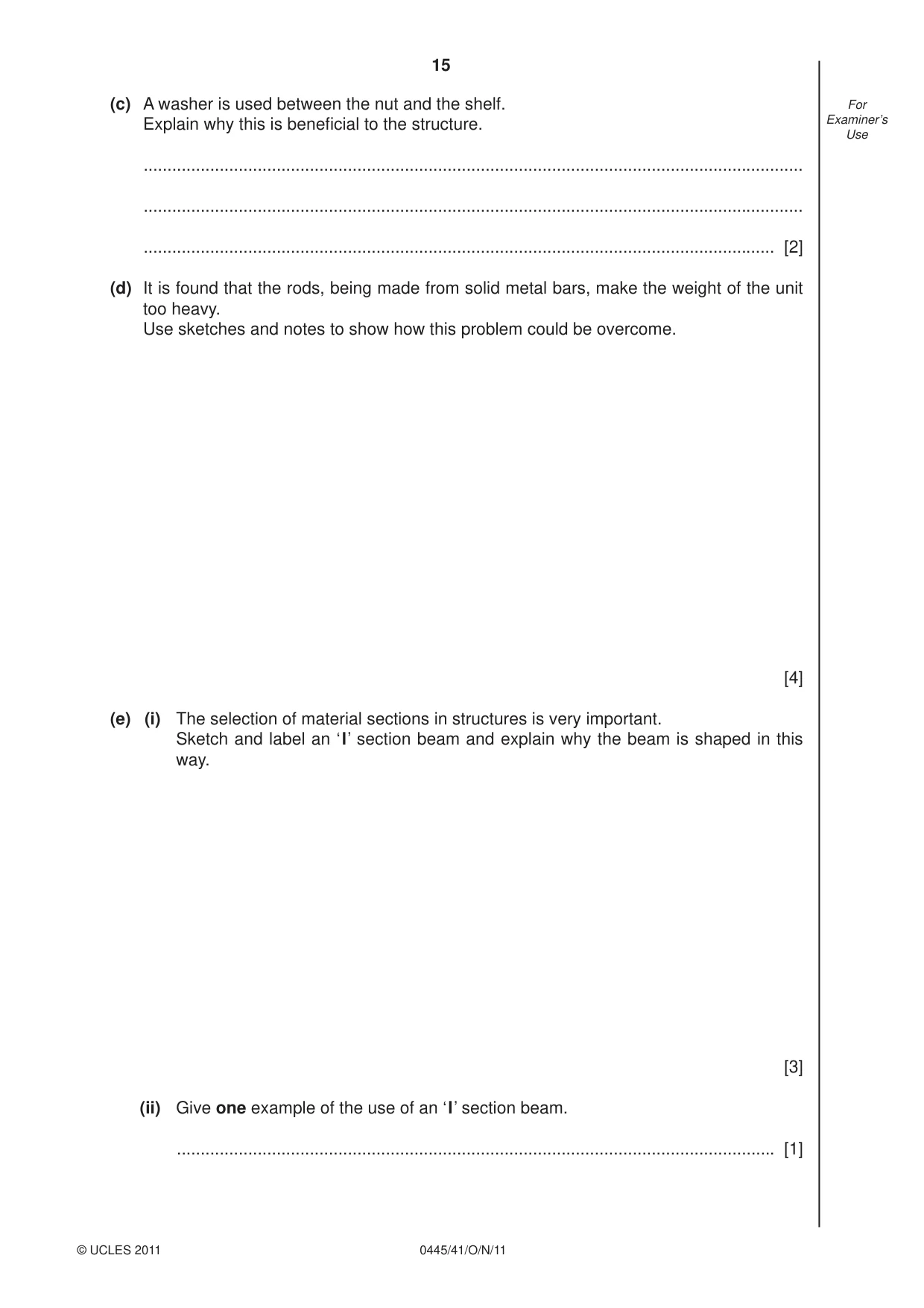
15 0445/41/O/N/11 © UCLES 2011 [Turn over For Examiner’s Use (c) A washer is used between the nut and the shelf. Explain why this is benefi cial to the structure. … … … [2] (d) It is found that the rods, being made from solid metal bars, make the weight of the unit too heavy. Use sketches and notes to show how this problem could be overcome. [4] (e) (i) The selection of material sections in structures is very important. Sketch and label an ‘I’ section beam and explain why the beam is shaped in this way. [3] (ii) Give one example of the use of an ‘I’ section beam. … [1]
Question paper, page 16
16 0445/41/O/N/11 Permission to reproduce items where third-party owned material protected by copyright is included has been sought and cleared where possible. Every reasonable effort has been made by the publisher (UCLES) to trace copyright holders, but if any items requiring clearance have unwittingly been included the publisher will be pleased to make amends at the earliest possible opportunity. University of Cambridge International Examinations is part of the Cambridge Assessment Group. Cambridge Assessment is the brand name of University of Cambridge Local Examinations Syndicate (UCLES), which is itself a department of the University of Cambridge. BLANK PAGE © UCLES 2011
Mark scheme, page 1
UNIVERSITY OF CAMBRIDGE INTERNATIONAL EXAMINATIONS International General Certificate of Secondary Education MARK SCHEME for the October/November 2011 question paper for the guidance of teachers 0445 DESIGN AND TECHNOLOGY 0445/41 Paper 4 (Systems and Control), maximum raw mark 50 This mark scheme is published as an aid to teachers and candidates, to indicate the requirements of the examination. It shows the basis on which Examiners were instructed to award marks. It does not indicate the details of the discussions that took place at an Examiners’ meeting before marking began, which would have considered the acceptability of alternative answers. Mark schemes must be read in conjunction with the question papers and the report on the examination. • Cambridge will not enter into discussions or correspondence in connection with these mark schemes. Cambridge is publishing the mark schemes for the October/November 2011 question papers for most IGCSE, GCE Advanced Level and Advanced Subsidiary Level syllabuses and some Ordinary Level syllabuses. www.XtremePapers.com
Mark scheme, page 2
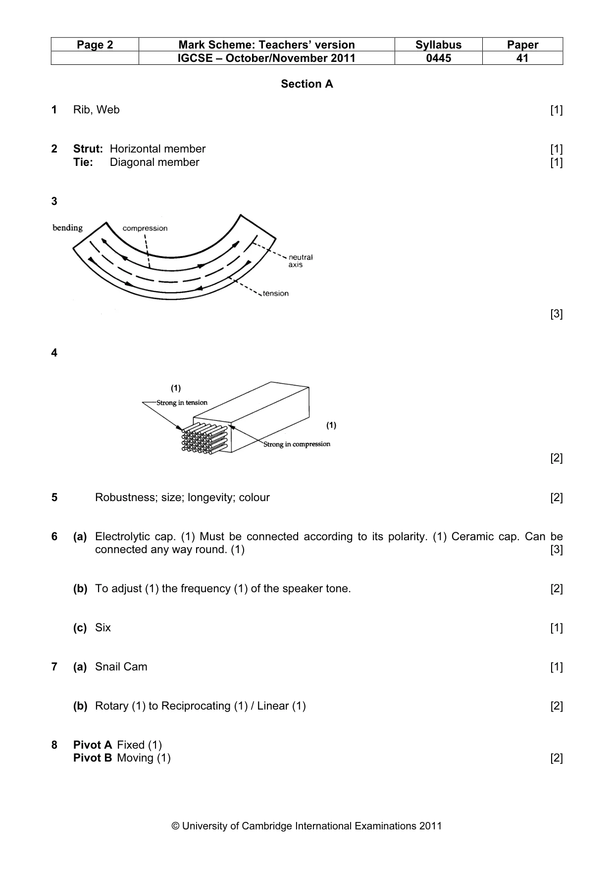
Page 2 Mark Scheme: Teachers’ version Syllabus Paper IGCSE – October/November 2011 0445 41 © University of Cambridge International Examinations 2011 Section A 1 Rib, Web [1] 2 Strut: Horizontal member [1] Tie: Diagonal member [1] 3 [3] 4 [2] 5 Robustness; size; longevity; colour [2] 6 (a) Electrolytic cap. (1) Must be connected according to its polarity. (1) Ceramic cap. Can be connected any way round. (1) [3] (b) To adjust (1) the frequency (1) of the speaker tone. [2] (c) Six [1] 7 (a) Snail Cam [1] (b) Rotary (1) to Reciprocating (1) / Linear (1) [2] 8 Pivot A Fixed (1) Pivot B Moving (1) [2] (1) (1)
Mark scheme, page 3
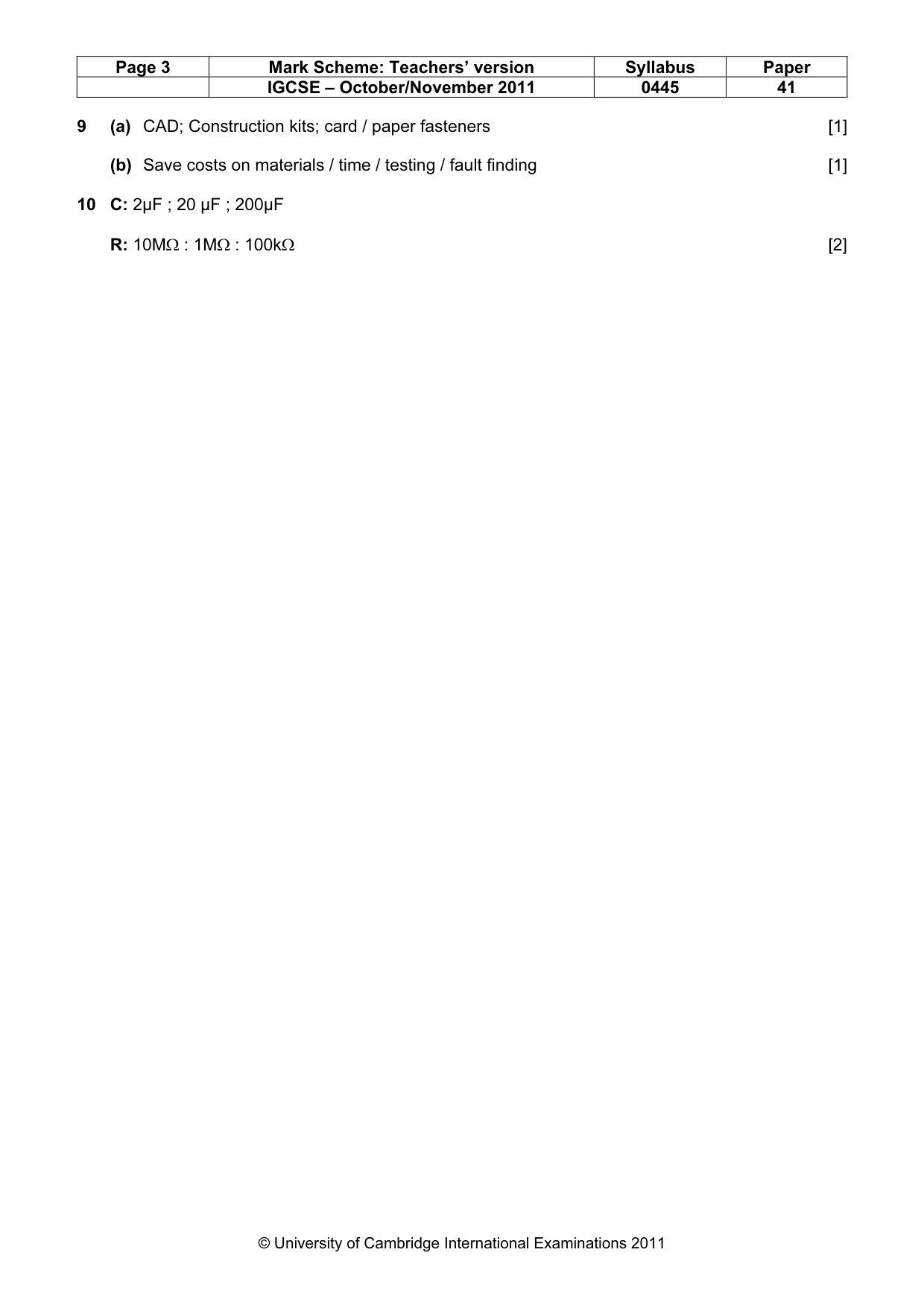
Page 3 Mark Scheme: Teachers’ version Syllabus Paper IGCSE – October/November 2011 0445 41 © University of Cambridge International Examinations 2011 9 (a) CAD; Construction kits; card / paper fasteners [1] (b) Save costs on materials / time / testing / fault finding [1] 10 C: 2µF ; 20 µF ; 200µF R: 10MΩ : 1MΩ : 100kΩ [2]
Mark scheme, page 4
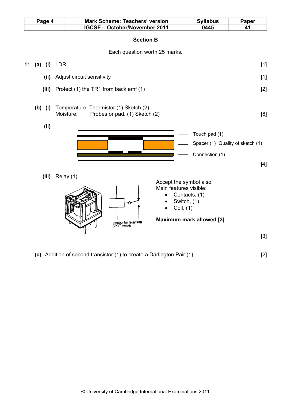
Page 4 Mark Scheme: Teachers’ version Syllabus Paper IGCSE – October/November 2011 0445 41 © University of Cambridge International Examinations 2011 Section B Each question worth 25 marks. 11 (a) (i) LDR [1] (ii) Adjust circuit sensitivity [1] (iii) Protect (1) the TR1 from back emf (1) [2] (b) (i) Temperature: Thermistor (1) Sketch (2) Moisture: Probes or pad. (1) Sketch (2) [6] (ii) [4] (iii) Relay (1) [3] (c) Addition of second transistor (1) to create a Darlington Pair (1) [2] Touch pad (1) Spacer (1) Quality of sketch (1) Connection (1) Accept the symbol also. Main features visible: • Contacts, (1) • Switch, (1) • Coil. (1) Maximum mark allowed [3]
Mark scheme, page 5
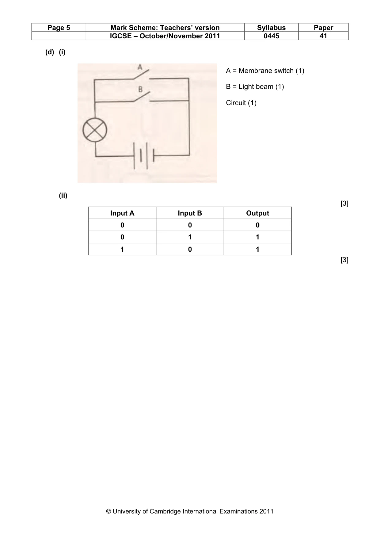
Page 5 Mark Scheme: Teachers’ version Syllabus Paper IGCSE – October/November 2011 0445 41 © University of Cambridge International Examinations 2011 (d) (i) (ii) [3] [3] Input A Input B Output 0 0 0 0 1 1 1 0 1 A = Membrane switch (1) B = Light beam (1) Circuit (1)
Mark scheme, page 6
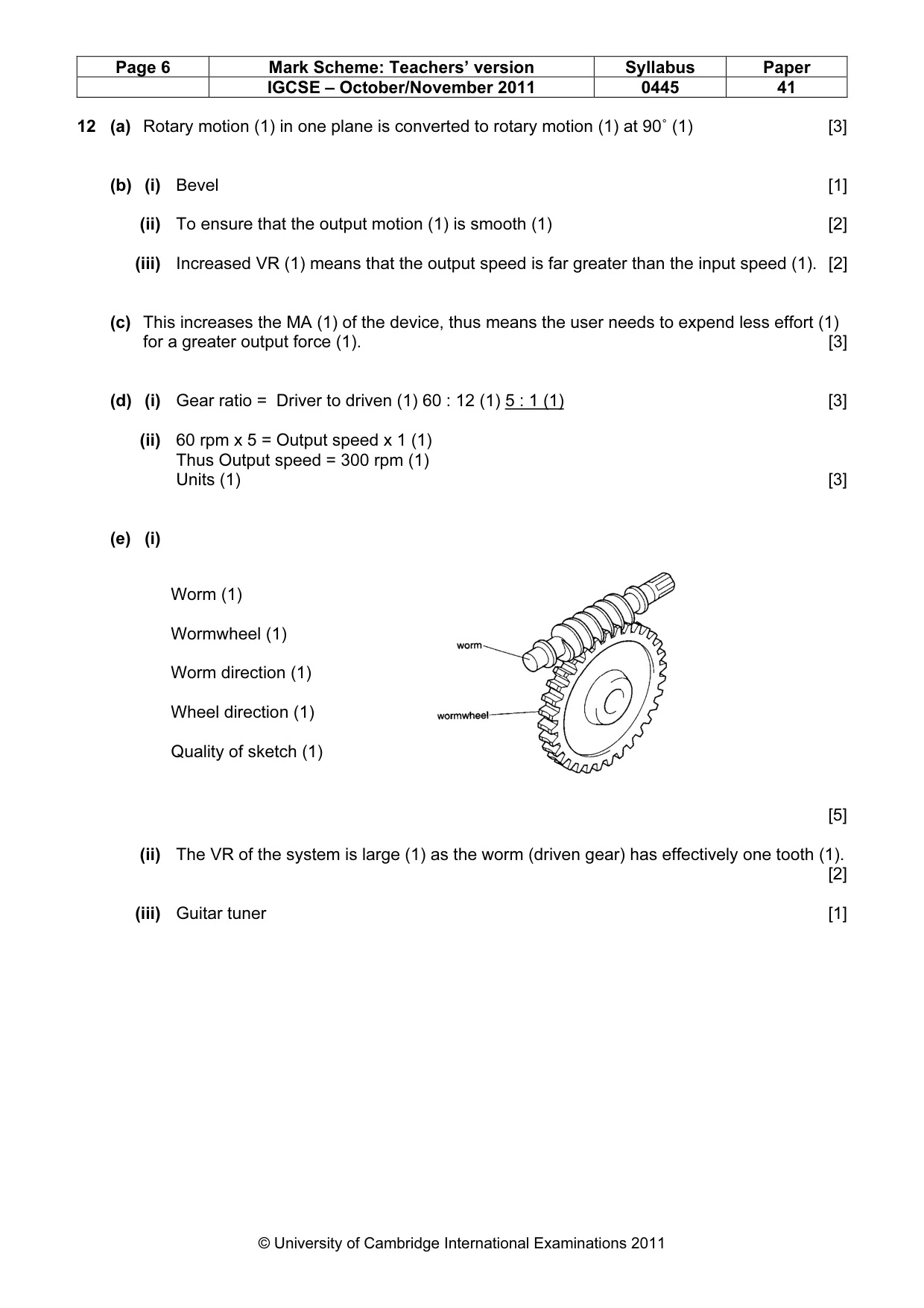
Page 6 Mark Scheme: Teachers’ version Syllabus Paper IGCSE – October/November 2011 0445 41 © University of Cambridge International Examinations 2011 12 (a) Rotary motion (1) in one plane is converted to rotary motion (1) at 90˚ (1) [3] (b) (i) Bevel [1] (ii) To ensure that the output motion (1) is smooth (1) [2] (iii) Increased VR (1) means that the output speed is far greater than the input speed (1). [2] (c) This increases the MA (1) of the device, thus means the user needs to expend less effort (1) for a greater output force (1). [3] (d) (i) Gear ratio = Driver to driven (1) 60 : 12 (1) 5 : 1 (1) [3] (ii) 60 rpm x 5 = Output speed x 1 (1) Thus Output speed = 300 rpm (1) Units (1) [3] (e) (i) [5] (ii) The VR of the system is large (1) as the worm (driven gear) has effectively one tooth (1). [2] (iii) Guitar tuner [1] Worm (1) Wormwheel (1) Worm direction (1) Wheel direction (1) Quality of sketch (1)
Mark scheme, page 7
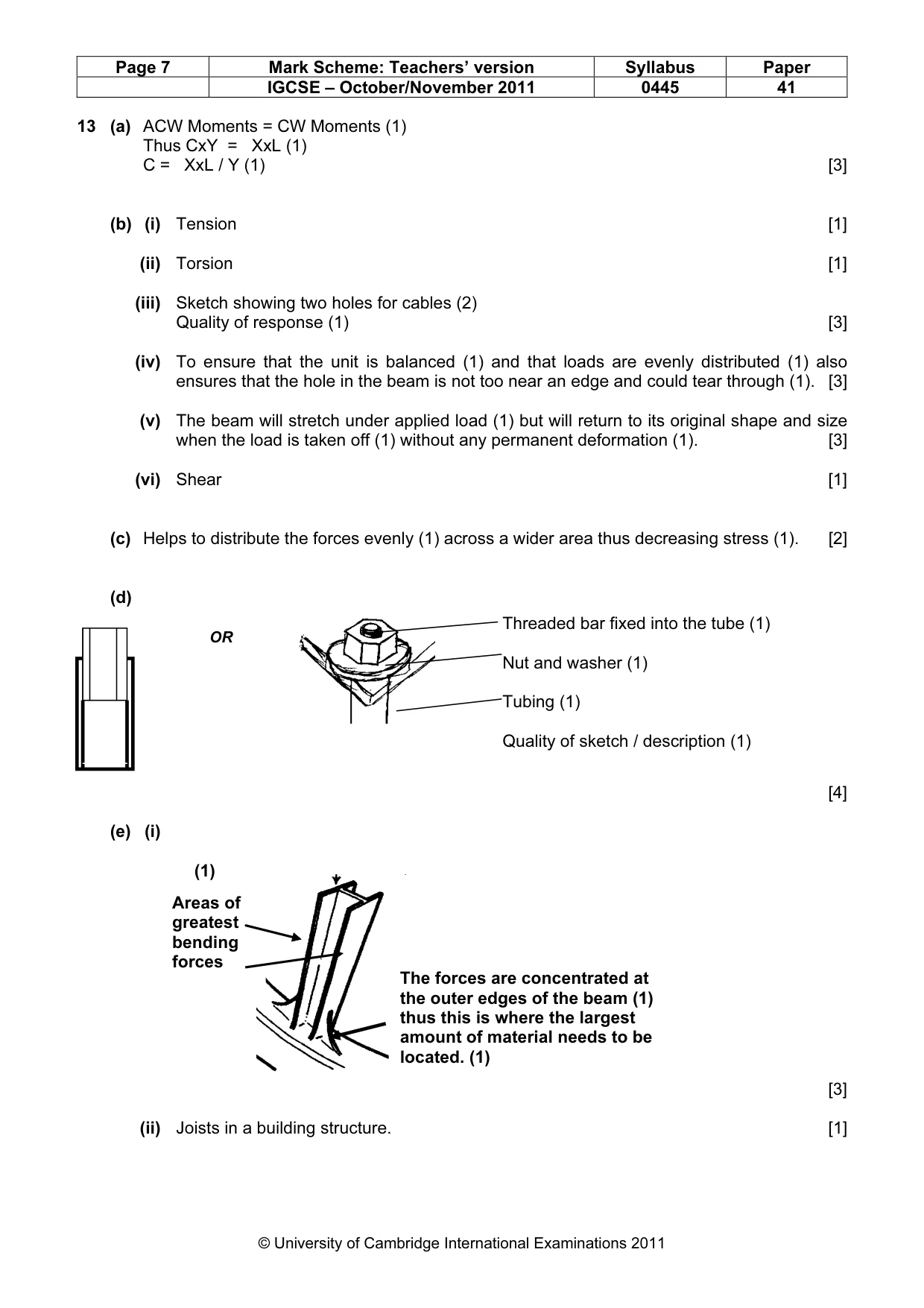
Page 7 Mark Scheme: Teachers’ version Syllabus Paper IGCSE – October/November 2011 0445 41 © University of Cambridge International Examinations 2011 13 (a) ACW Moments = CW Moments (1) Thus CxY = XxL (1) C = XxL / Y (1) [3] (b) (i) Tension [1] (ii) Torsion [1] (iii) Sketch showing two holes for cables (2) Quality of response (1) [3] (iv) To ensure that the unit is balanced (1) and that loads are evenly distributed (1) also ensures that the hole in the beam is not too near an edge and could tear through (1). [3] (v) The beam will stretch under applied load (1) but will return to its original shape and size when the load is taken off (1) without any permanent deformation (1). [3] (vi) Shear [1] (c) Helps to distribute the forces evenly (1) across a wider area thus decreasing stress (1). [2] (d) [4] (e) (i) [3] (ii) Joists in a building structure. [1] Areas of greatest bending forces (1) The forces are concentrated at the outer edges of the beam (1) thus this is where the largest amount of material needs to be located. (1) Threaded bar fixed into the tube (1) Nut and washer (1) Tubing (1) Quality of sketch / description (1) OR