Cambridge IGCSE Design and Technology 0445 — 2010 Oct/Nov Paper 4 · Variant 3
0445/43/O/N/10 · 50 marks · ≈56 min
The question paper and its mark scheme, free to read here and free to download. This is Cambridge’s own paper, exactly as it was sat.
Question paper16 pages

Mark scheme6 pages
Answers below. Sit the paper first if you are practising.
Paper as text
Question paper, page 1
[Turn over *1377926229* READ THESE INSTRUCTIONS FIRST Write your Centre number, candidate number and name on all the work you hand in. Write in dark blue or black pen. You may use a soft pencil for any diagrams or graphs. Do not use staples, paper clips, highlighters, glue or correction fl uid. DO NOT WRITE IN ANY BARCODES. You may use a calculator. Section A Answer all questions. Section B Answer one question. At the end of the examination, fasten all your work securely together. The number of marks is given in brackets [ ] at the end of each question or part question. For Examiner’s Use Section A Section B Total DESIGN AND TECHNOLOGY 0445/43 Paper 4 Systems and Control October/November 2010 1 hour Candidates answer on the Question Paper. No Additional Materials are required. To be taken together with Paper 1 in one session of 2 hours and 15 minutes. UNIVERSITY OF CAMBRIDGE INTERNATIONAL EXAMINATIONS International General Certifi cate of Secondary Education This document consists of an 14 printed pages and 2 blank pages. [Turn over IB10 11_0445_43/FP © UCLES 2010 www.XtremePapers.com
Question paper, page 2
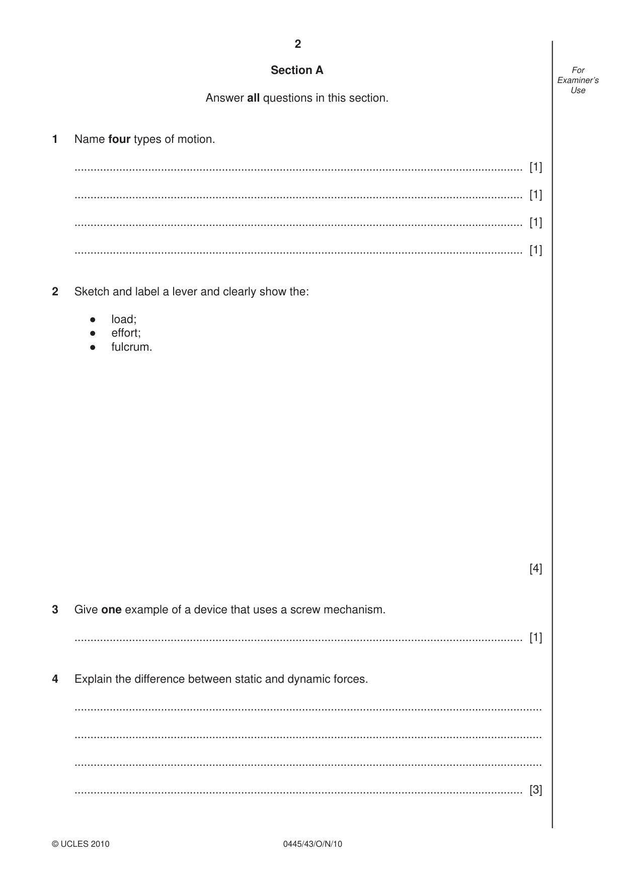
2 0445/43/O/N/10 © UCLES 2010 For Examiner’s Use Section A Answer all questions in this section. 1 Name four types of motion. … [1] … [1] … [1] … [1] 2 Sketch and label a lever and clearly show the: ● load; ● effort; ● fulcrum. [4] 3 Give one example of a device that uses a screw mechanism. … [1] 4 Explain the difference between static and dynamic forces. … … … … [3]
Question paper, page 3
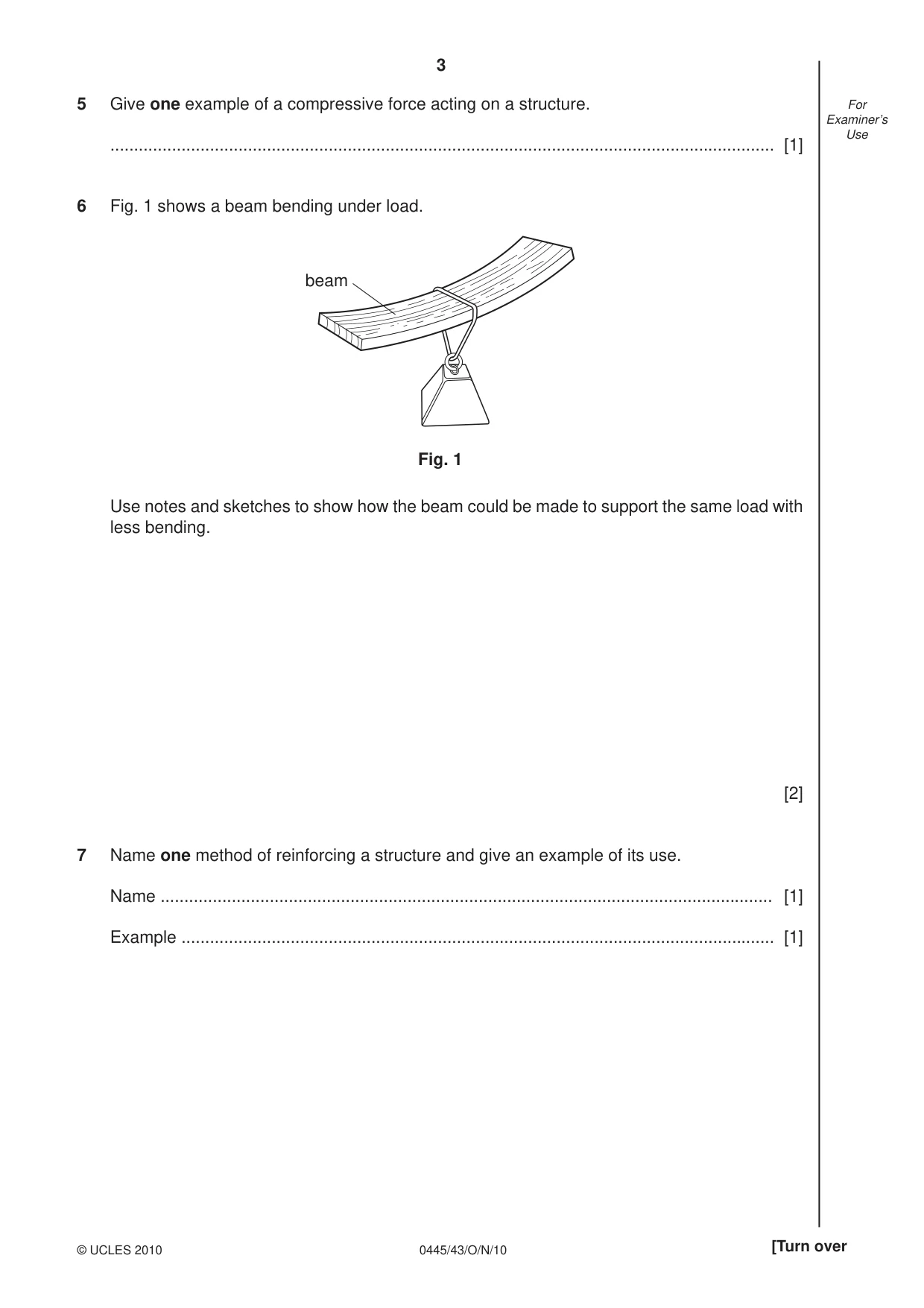
3 0445/43/O/N/10 © UCLES 2010 [Turn over For Examiner’s Use 5 Give one example of a compressive force acting on a structure. … [1] 6 Fig. 1 shows a beam bending under load. beam Fig. 1 Use notes and sketches to show how the beam could be made to support the same load with less bending. [2] 7 Name one method of reinforcing a structure and give an example of its use. Name … [1] Example … [1]
Question paper, page 4
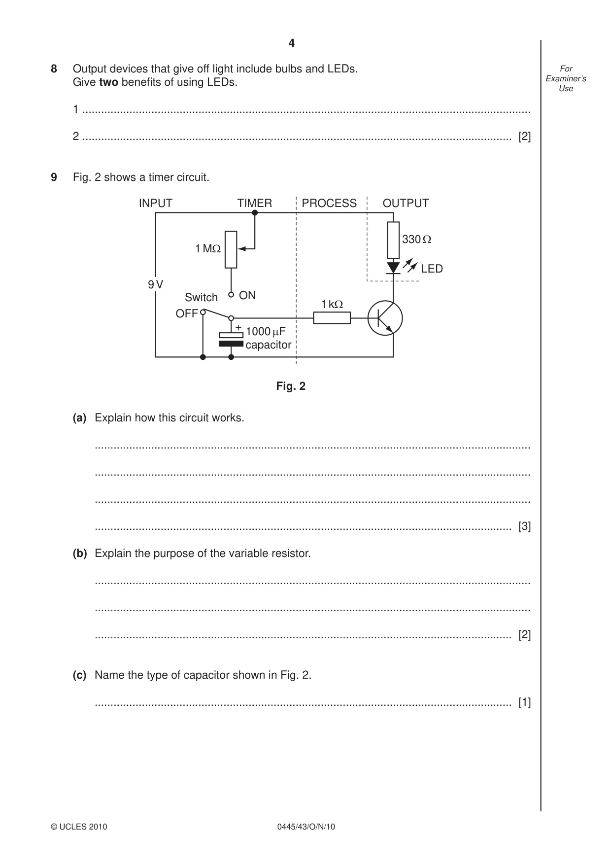
4 0445/43/O/N/10 © UCLES 2010 For Examiner’s Use 8 Output devices that give off light include bulbs and LEDs. Give two benefi ts of using LEDs. 1 … 2 … [2] 9 Fig. 2 shows a timer circuit. 9 V + 1000 µF capacitor Switch ON OFF INPUT TIMER PROCESS OUTPUT 1 MΩ 1 kΩ 330 Ω LED Fig. 2 (a) Explain how this circuit works. … … … … [3] (b) Explain the purpose of the variable resistor. … … … [2] (c) Name the type of capacitor shown in Fig. 2. … [1]
Question paper, page 5
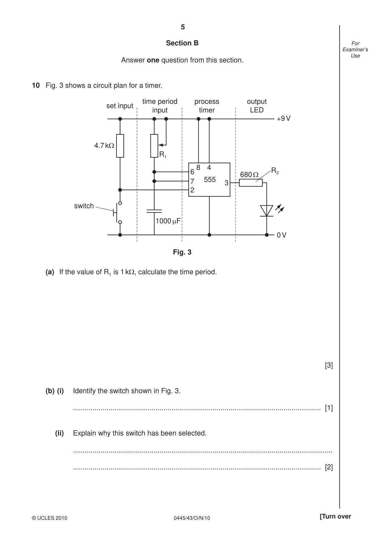
5 0445/43/O/N/10 © UCLES 2010 [Turn over For Examiner’s Use Section B Answer one question from this section. 10 Fig. 3 shows a circuit plan for a timer. 4.7 kΩ 680 Ω R1 R2 set input time period input process timer output LED 1000 µF +9 V 0 V 555 8 4 6 7 2 3 Fig. 3 switch (a) If the value of R1 is 1 kΩ, calculate the time period. [3] (b) (i) Identify the switch shown in Fig. 3. … [1] (ii) Explain why this switch has been selected. … … [2]
Question paper, page 6
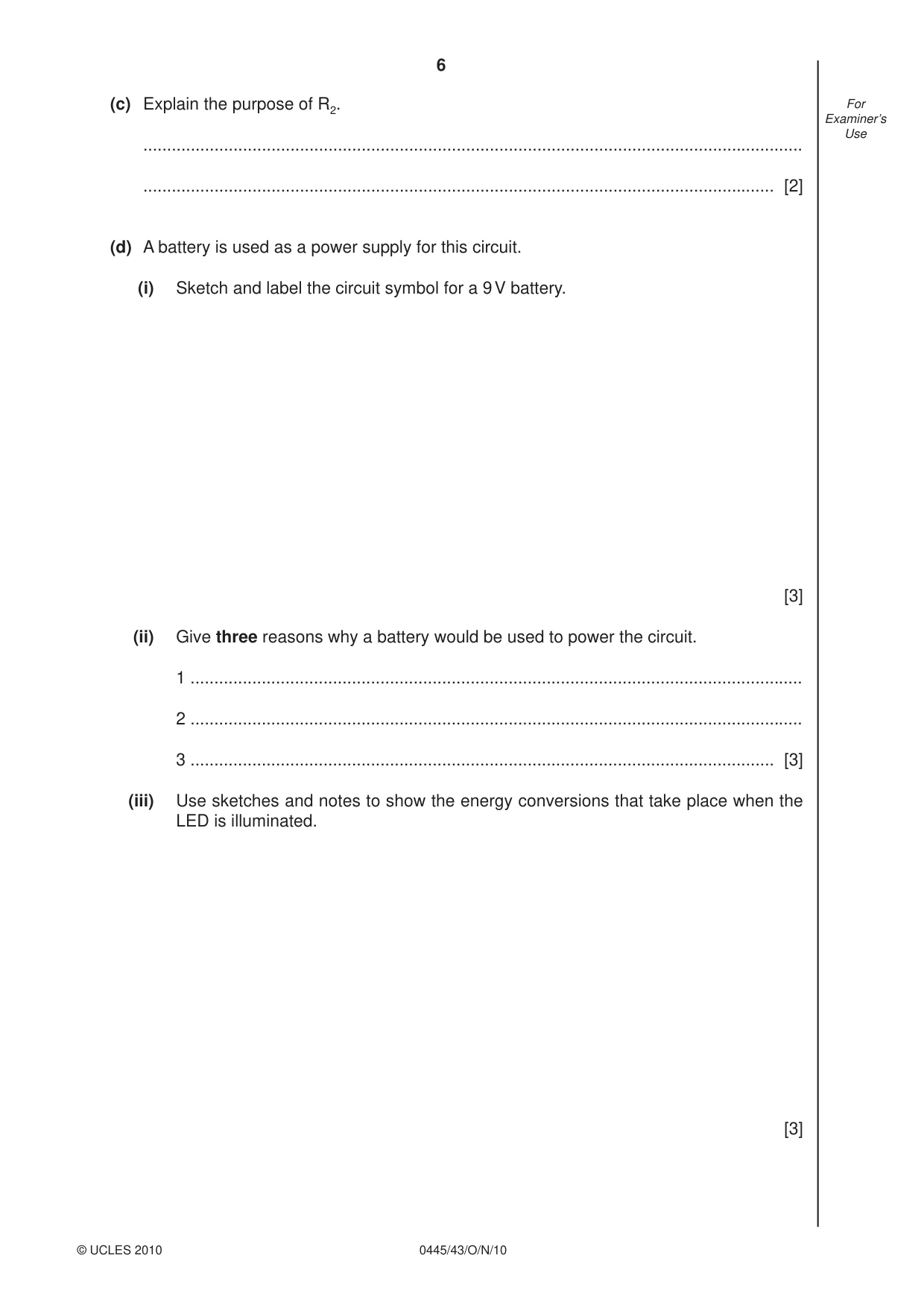
6 0445/43/O/N/10 © UCLES 2010 For Examiner’s Use (c) Explain the purpose of R2. … … [2] (d) A battery is used as a power supply for this circuit. (i) Sketch and label the circuit symbol for a 9 V battery. [3] (ii) Give three reasons why a battery would be used to power the circuit. 1 … 2 … 3 … [3] (iii) Use sketches and notes to show the energy conversions that take place when the LED is illuminated. [3]
Question paper, page 7
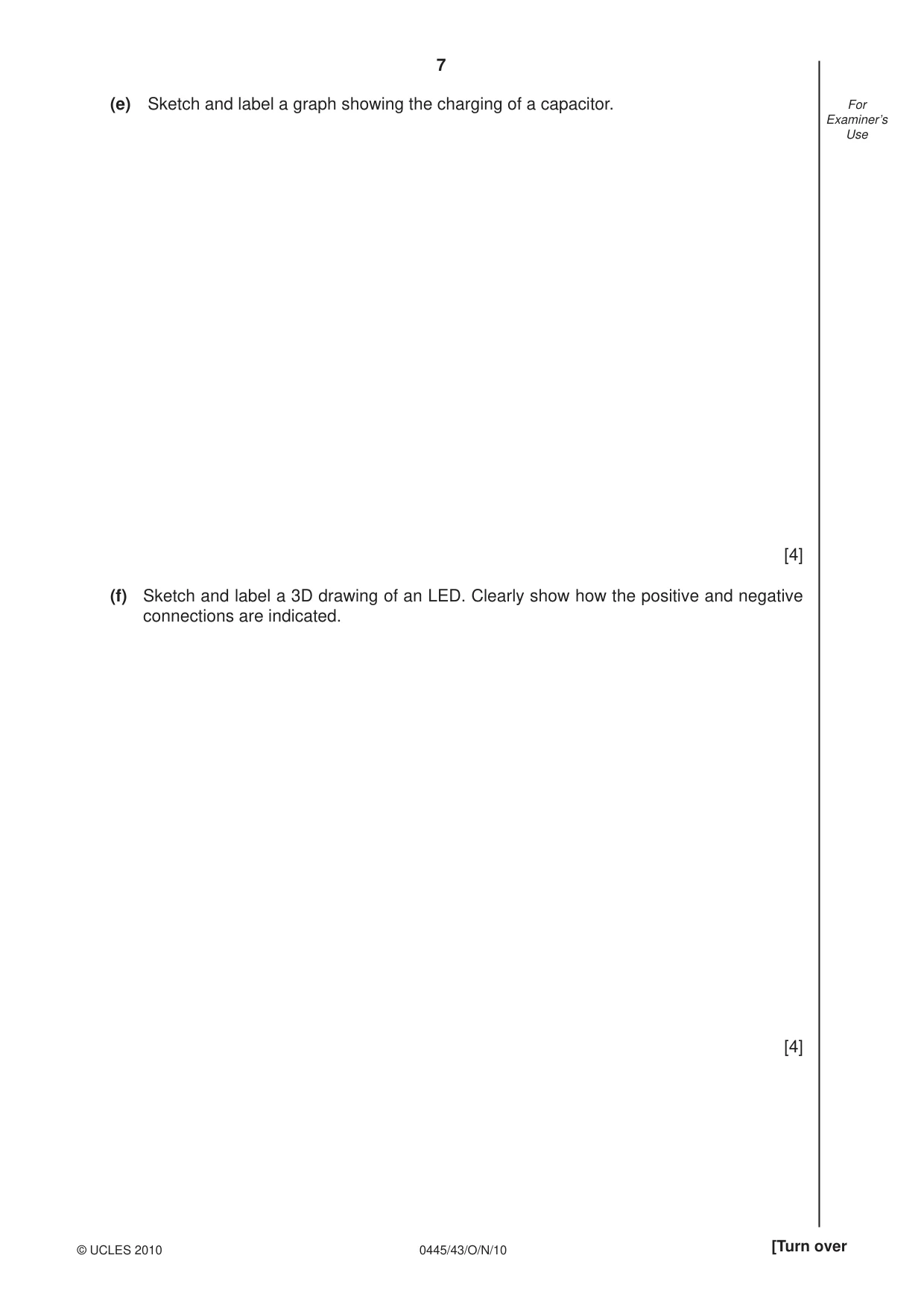
7 0445/43/O/N/10 © UCLES 2010 [Turn over For Examiner’s Use (e) Sketch and label a graph showing the charging of a capacitor. [4] (f) Sketch and label a 3D drawing of an LED. Clearly show how the positive and negative connections are indicated. [4]
Question paper, page 8
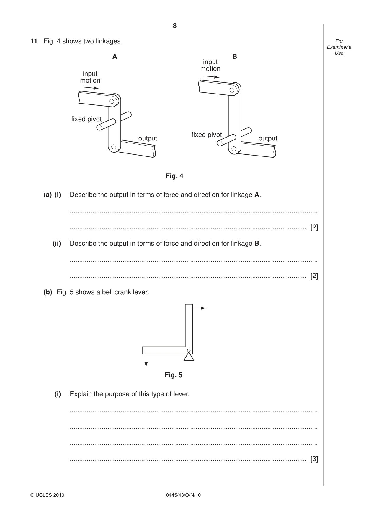
8 0445/43/O/N/10 © UCLES 2010 For Examiner’s Use 11 Fig. 4 shows two linkages. input motion A B Fig. 4 fixed pivot output input motion fixed pivot output (a) (i) Describe the output in terms of force and direction for linkage A. … … [2] (ii) Describe the output in terms of force and direction for linkage B. … … [2] (b) Fig. 5 shows a bell crank lever. Fig. 5 (i) Explain the purpose of this type of lever. … … … … [3]
Question paper, page 9
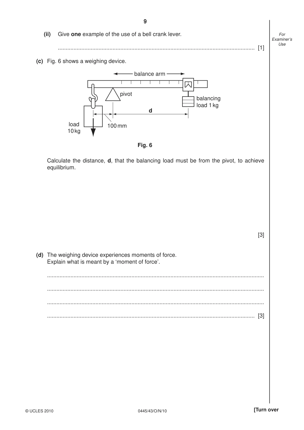
9 0445/43/O/N/10 © UCLES 2010 [Turn over For Examiner’s Use (ii) Give one example of the use of a bell crank lever. … [1] (c) Fig. 6 shows a weighing device. balancing load 1 kg load 10 kg d Fig. 6 pivot balance arm 100 mm Calculate the distance, d, that the balancing load must be from the pivot, to achieve equilibrium. [3] (d) The weighing device experiences moments of force. Explain what is meant by a ‘moment of force’. … … … … [3]
Question paper, page 10
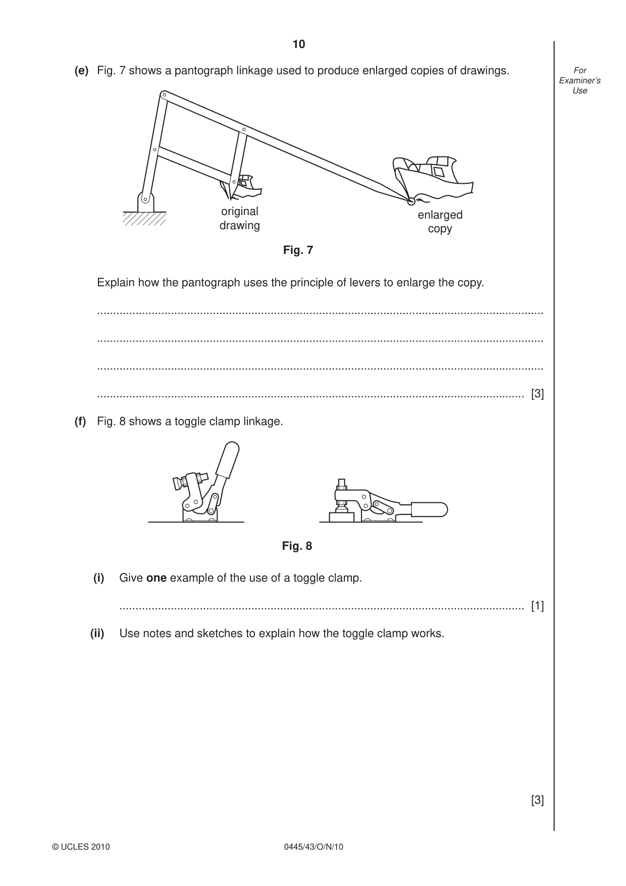
10 0445/43/O/N/10 © UCLES 2010 For Examiner’s Use (e) Fig. 7 shows a pantograph linkage used to produce enlarged copies of drawings. Fig. 7 original drawing enlarged copy Explain how the pantograph uses the principle of levers to enlarge the copy. … … … … [3] (f) Fig. 8 shows a toggle clamp linkage. Fig. 8 (i) Give one example of the use of a toggle clamp. … [1] (ii) Use notes and sketches to explain how the toggle clamp works. [3]
Question paper, page 11
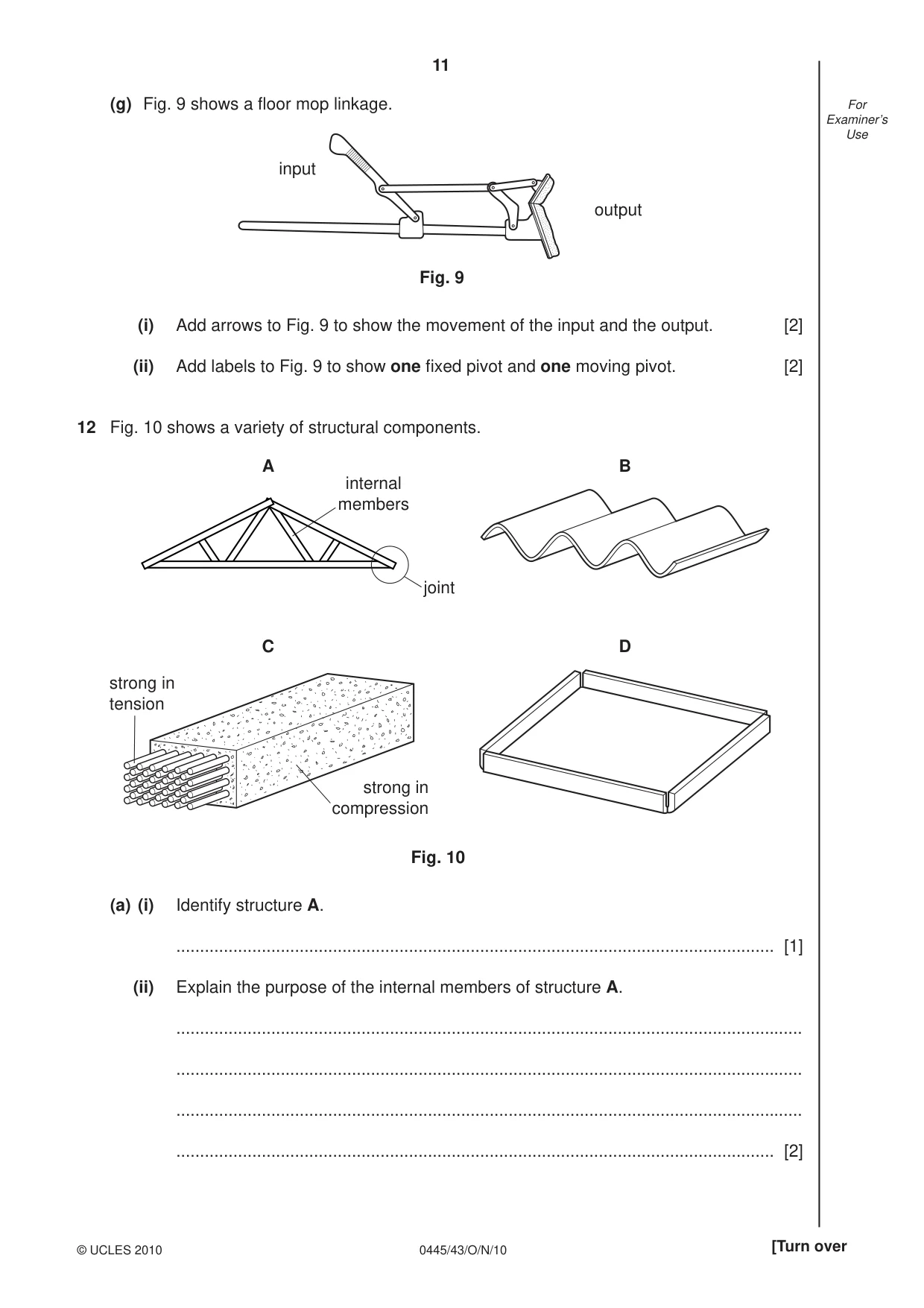
11 0445/43/O/N/10 © UCLES 2010 [Turn over For Examiner’s Use (g) Fig. 9 shows a fl oor mop linkage. input output Fig. 9 (i) Add arrows to Fig. 9 to show the movement of the input and the output. [2] (ii) Add labels to Fig. 9 to show one fi xed pivot and one moving pivot. [2] 12 Fig. 10 shows a variety of structural components. A B C D internal members joint strong in tension strong in compression Fig. 10 (a) (i) Identify structure A. … [1] (ii) Explain the purpose of the internal members of structure A. … … … … [2]
Question paper, page 12
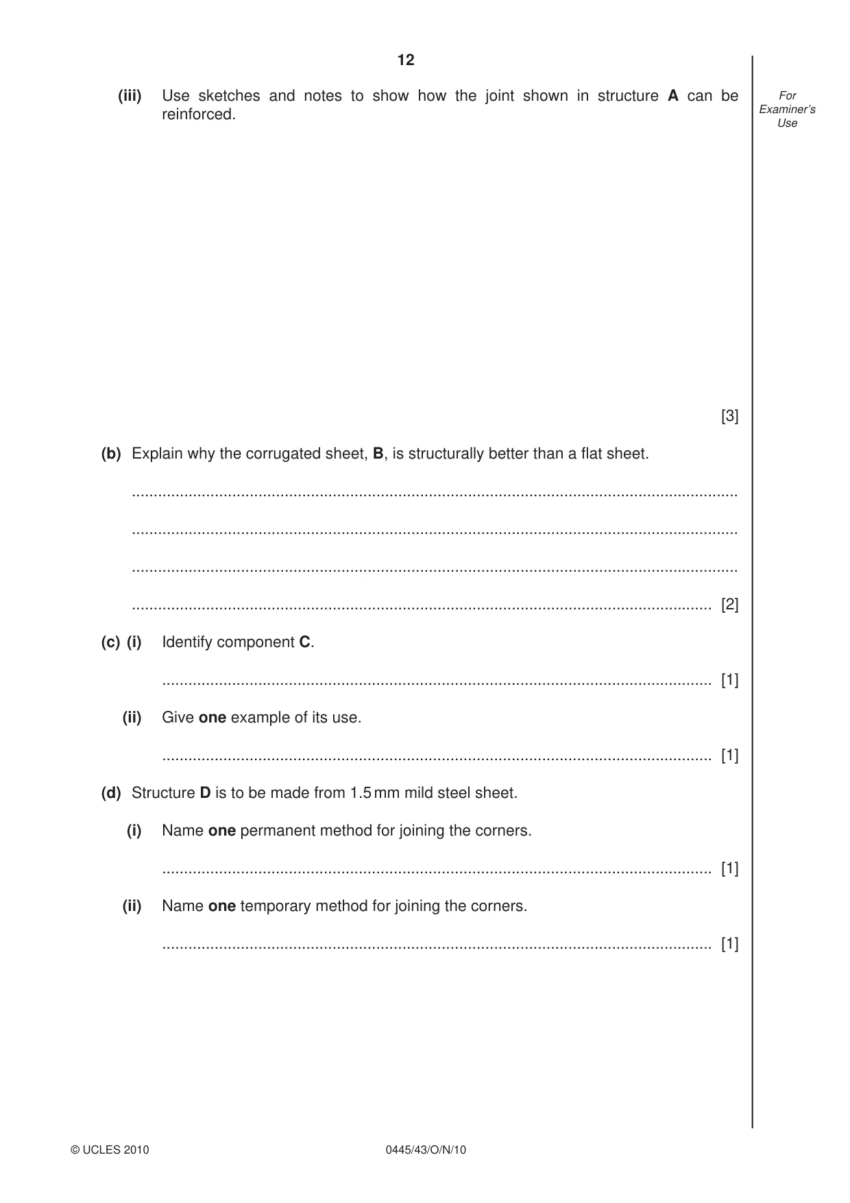
12 0445/43/O/N/10 © UCLES 2010 For Examiner’s Use (iii) Use sketches and notes to show how the joint shown in structure A can be reinforced. [3] (b) Explain why the corrugated sheet, B, is structurally better than a fl at sheet. … … … … [2] (c) (i) Identify component C. … [1] (ii) Give one example of its use. … [1] (d) Structure D is to be made from 1.5 mm mild steel sheet. (i) Name one permanent method for joining the corners. … [1] (ii) Name one temporary method for joining the corners. … [1]
Question paper, page 13
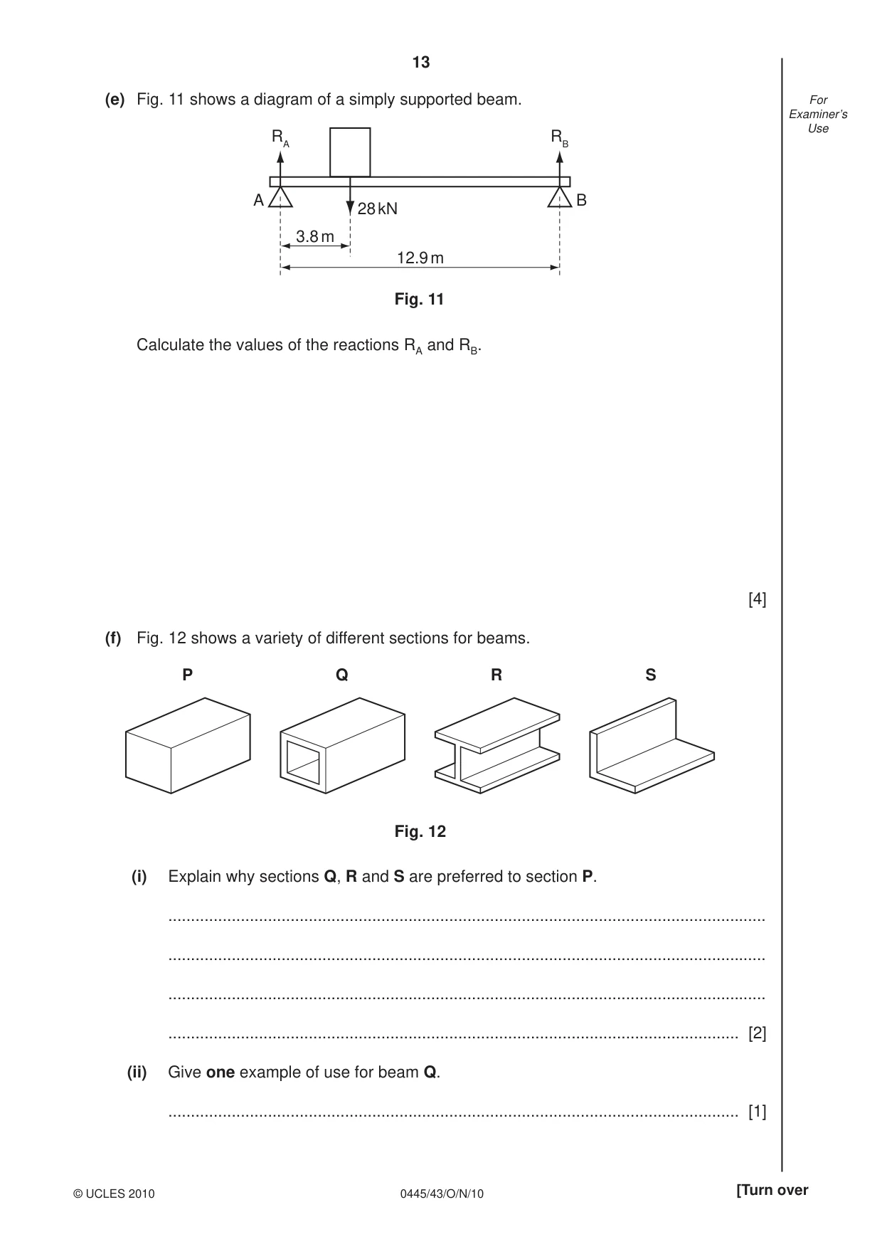
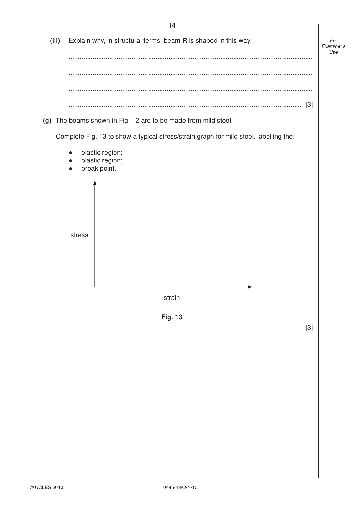
13 0445/43/O/N/10 © UCLES 2010 [Turn over For Examiner’s Use (e) Fig. 11 shows a diagram of a simply supported beam. RA RB A B 3.8 m 12.9 m 28 kN Fig. 11 Calculate the values of the reactions RA and RB. [4] (f) Fig. 12 shows a variety of different sections for beams. P Q R S Fig. 12 (i) Explain why sections Q, R and S are preferred to section P. … … … … [2] (ii) Give one example of use for beam Q. … [1]
Question paper, page 14
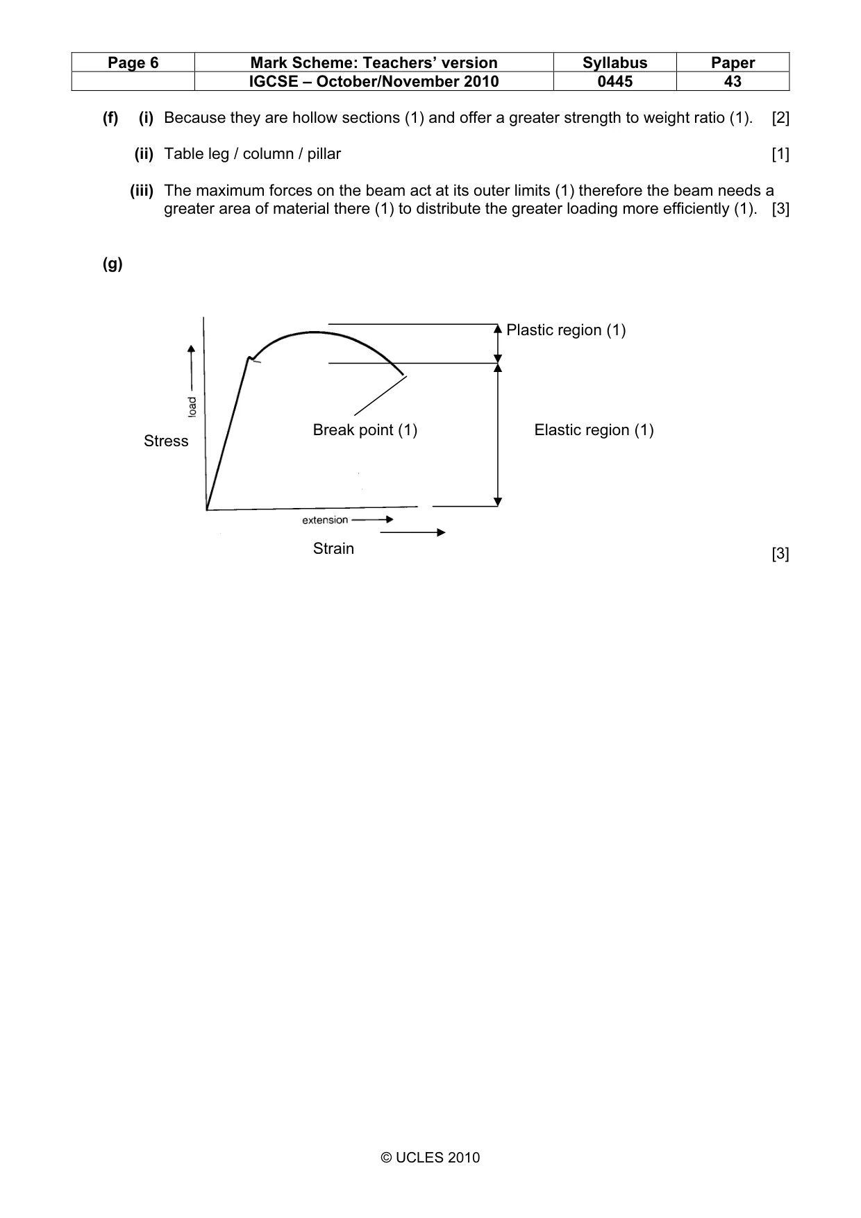
14 0445/43/O/N/10 © UCLES 2010 For Examiner’s Use (iii) Explain why, in structural terms, beam R is shaped in this way. … … … … [3] (g) The beams shown in Fig. 12 are to be made from mild steel. Complete Fig. 13 to show a typical stress/strain graph for mild steel, labelling the: ● elastic region; ● plastic region; ● break point. stress strain Fig. 13 [3]
Question paper, page 15
15 0445/43/O/N/10 BLANK PAGE © UCLES 2010
Question paper, page 16
16 0445/43/O/N/10 Permission to reproduce items where third-party owned material protected by copyright is included has been sought and cleared where possible. Every reasonable effort has been made by the publisher (UCLES) to trace copyright holders, but if any items requiring clearance have unwittingly been included the publisher will be pleased to make amends at the earliest possible opportunity. University of Cambridge International Examinations is part of the Cambridge Assessment Group. Cambridge Assessment is the brand name of University of Cambridge Local Examinations Syndicate (UCLES), which is itself a department of the University of Cambridge. BLANK PAGE © UCLES 2010
Mark scheme, page 1
UNIVERSITY OF CAMBRIDGE INTERNATIONAL EXAMINATIONS International General Certificate of Secondary Education MARK SCHEME for the October/November 2010 question paper for the guidance of teachers 0445 DESIGN AND TECHNOLOGY 0445/43 Paper 4 (Systems and Control), maximum raw mark 50 This mark scheme is published as an aid to teachers and candidates, to indicate the requirements of the examination. It shows the basis on which Examiners were instructed to award marks. It does not indicate the details of the discussions that took place at an Examiners’ meeting before marking began, which would have considered the acceptability of alternative answers. Mark schemes must be read in conjunction with the question papers and the report on the examination. • CIE will not enter into discussions or correspondence in connection with these mark schemes. CIE is publishing the mark schemes for the October/November 2010 question papers for most IGCSE, GCE Advanced Level and Advanced Subsidiary Level syllabuses and some Ordinary Level syllabuses. www.XtremePapers.com
Mark scheme, page 2
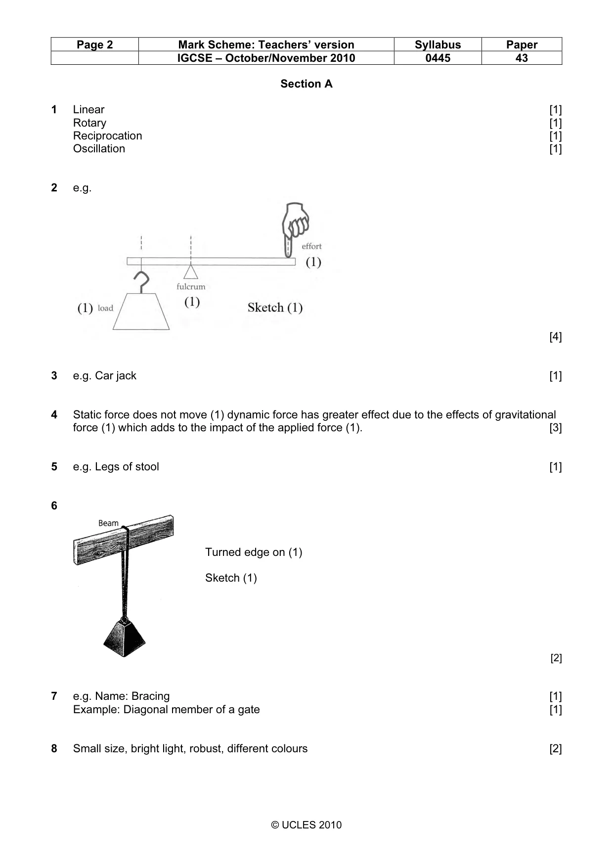
Page 2 Mark Scheme: Teachers’ version Syllabus Paper IGCSE – October/November 2010 0445 43 © UCLES 2010 Section A 1 Linear [1] Rotary [1] Reciprocation [1] Oscillation [1] 2 e.g. [4] 3 e.g. Car jack [1] 4 Static force does not move (1) dynamic force has greater effect due to the effects of gravitational force (1) which adds to the impact of the applied force (1). [3] 5 e.g. Legs of stool [1] 6 [2] 7 e.g. Name: Bracing [1] Example: Diagonal member of a gate [1] 8 Small size, bright light, robust, different colours [2] Turned edge on (1) Sketch (1)
Mark scheme, page 3
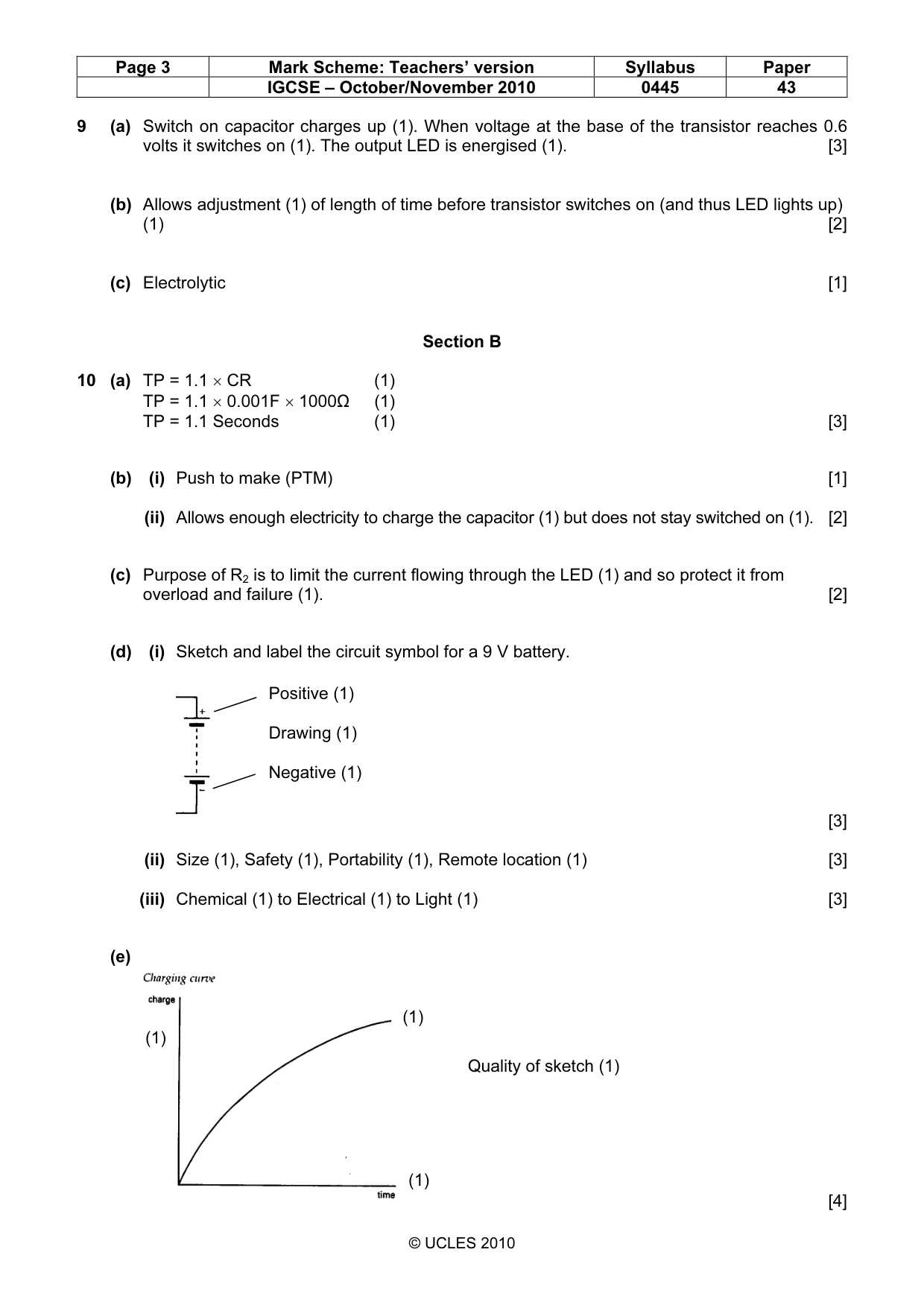
Page 3 Mark Scheme: Teachers’ version Syllabus Paper IGCSE – October/November 2010 0445 43 © UCLES 2010 9 (a) Switch on capacitor charges up (1). When voltage at the base of the transistor reaches 0.6 volts it switches on (1). The output LED is energised (1). [3] (b) Allows adjustment (1) of length of time before transistor switches on (and thus LED lights up) (1) [2] (c) Electrolytic [1] Section B 10 (a) TP = 1.1 × CR (1) TP = 1.1 × 0.001F × 1000Ω (1) TP = 1.1 Seconds (1) [3] (b) (i) Push to make (PTM) [1] (ii) Allows enough electricity to charge the capacitor (1) but does not stay switched on (1). [2] (c) Purpose of R2 is to limit the current flowing through the LED (1) and so protect it from overload and failure (1). [2] (d) (i) Sketch and label the circuit symbol for a 9 V battery. [3] (ii) Size (1), Safety (1), Portability (1), Remote location (1) [3] (iii) Chemical (1) to Electrical (1) to Light (1) [3] (e) [4] Positive (1) Drawing (1) Negative (1) (1) (1) (1) Quality of sketch (1)
Mark scheme, page 4
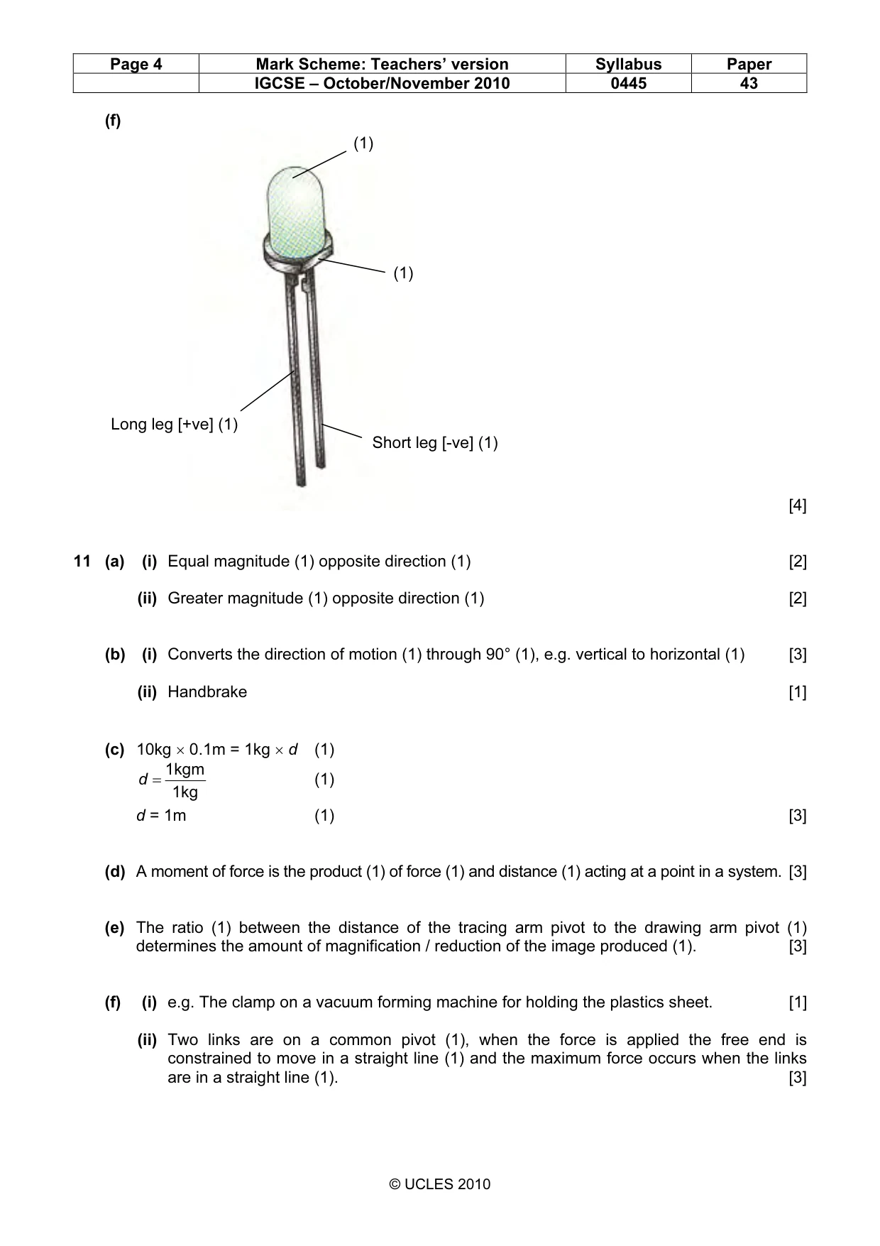
Page 4 Mark Scheme: Teachers’ version Syllabus Paper IGCSE – October/November 2010 0445 43 © UCLES 2010 (f) [4] 11 (a) (i) Equal magnitude (1) opposite direction (1) [2] (ii) Greater magnitude (1) opposite direction (1) [2] (b) (i) Converts the direction of motion (1) through 90° (1), e.g. vertical to horizontal (1) [3] (ii) Handbrake [1] (c) 10kg × 0.1m = 1kg × d (1) 1kg 1kgm = d (1) d = 1m (1) [3] (d) A moment of force is the product (1) of force (1) and distance (1) acting at a point in a system. [3] (e) The ratio (1) between the distance of the tracing arm pivot to the drawing arm pivot (1) determines the amount of magnification / reduction of the image produced (1). [3] (f) (i) e.g. The clamp on a vacuum forming machine for holding the plastics sheet. [1] (ii) Two links are on a common pivot (1), when the force is applied the free end is constrained to move in a straight line (1) and the maximum force occurs when the links are in a straight line (1). [3] (1) (1) Short leg [-ve] (1) Long leg [+ve] (1)
Mark scheme, page 5
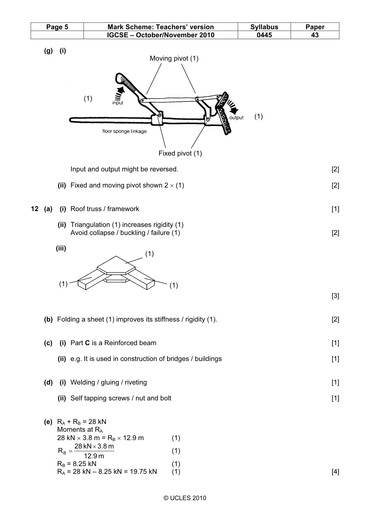
Page 5 Mark Scheme: Teachers’ version Syllabus Paper IGCSE – October/November 2010 0445 43 © UCLES 2010 (g) (i) Moving pivot (1) Fixed pivot (1) Input and output might be reversed. [2] (ii) Fixed and moving pivot shown 2 × (1) [2] 12 (a) (i) Roof truss / framework [1] (ii) Triangulation (1) increases rigidity (1) Avoid collapse / buckling / failure (1) [2] (iii) [3] (b) Folding a sheet (1) improves its stiffness / rigidity (1). [2] (c) (i) Part C is a Reinforced beam [1] (ii) e.g. It is used in construction of bridges / buildings [1] (d) (i) Welding / gluing / riveting [1] (ii) Self tapping screws / nut and bolt [1] (e) RA + RB = 28 kN Moments at RA 28 kN × 3.8 m = RB × 12.9 m (1) m 12.9 m 3.8 kN 28 RB × = (1) RB = 8.25 kN (1) RA = 28 kN – 8.25 kN = 19.75 kN (1) [4] (1) (1) (1) (1) (1)
Mark scheme, page 6
Page 6 Mark Scheme: Teachers’ version Syllabus Paper IGCSE – October/November 2010 0445 43 © UCLES 2010 (f) (i) Because they are hollow sections (1) and offer a greater strength to weight ratio (1). [2] (ii) Table leg / column / pillar [1] (iii) The maximum forces on the beam act at its outer limits (1) therefore the beam needs a greater area of material there (1) to distribute the greater loading more efficiently (1). [3] (g) [3] Strain Plastic region (1) Elastic region (1) Break point (1) Stress
What you needed in this session
Cambridge’s own grade thresholds for 2010 Oct/Nov, Paper 4 · Variant 3. A higher threshold means an easier paper — the bar moves with how the cohort did.