Cambridge IGCSE Design and Technology 0445 — 2010 May/June Paper 4 · Variant 3
0445/43/M/J/10 · 50 marks · ≈56 min
The question paper and its mark scheme, free to read here and free to download. This is Cambridge’s own paper, exactly as it was sat.
Question paper16 pages





Mark scheme
No mark scheme is in the library for this paper.
Paper as text
Question paper, page 1
[Turn over *3268929210* READ THESE INSTRUCTIONS FIRST Write your Centre number, candidate number and name on all the work you hand in. Write in dark blue or black pen. You may use a soft pencil for any diagrams or graphs. Do not use staples, paper clips, highlighters, glue or correction fl uid. DO NOT WRITE IN ANY BARCODES. You may use a calculator. Section A Answer all questions. Section B Answer one question. At the end of the examination, fasten all your work securely together. The number of marks is given in brackets [ ] at the end of each question or part question. For Examiner’s Use Section A Section B Total DESIGN AND TECHNOLOGY 0445/43 Paper 4 Systems and Control May/June 2010 1 hour Candidates answer on the Question Paper. No Additional Materials are required. To be taken together with Paper 1 in one session of 2 hours and 15 minutes. UNIVERSITY OF CAMBRIDGE INTERNATIONAL EXAMINATIONS International General Certifi cate of Secondary Education This document consists of an 15 printed pages and 1 blank page. [Turn over IB10 06_0445_43/2RP © UCLES 2010 www.XtremePapers.com
Question paper, page 2
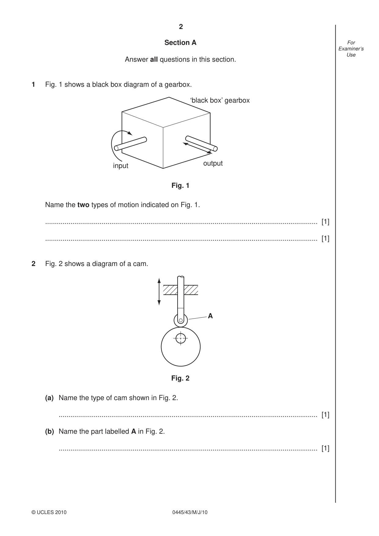
2 0445/43/M/J/10 © UCLES 2010 For Examiner’s Use Section A Answer all questions in this section. 1 Fig. 1 shows a black box diagram of a gearbox. ‘black box’ gearbox input output Fig. 1 Name the two types of motion indicated on Fig. 1. … [1] … [1] 2 Fig. 2 shows a diagram of a cam. A Fig. 2 (a) Name the type of cam shown in Fig. 2. … [1] (b) Name the part labelled A in Fig. 2. … [1]
Question paper, page 3
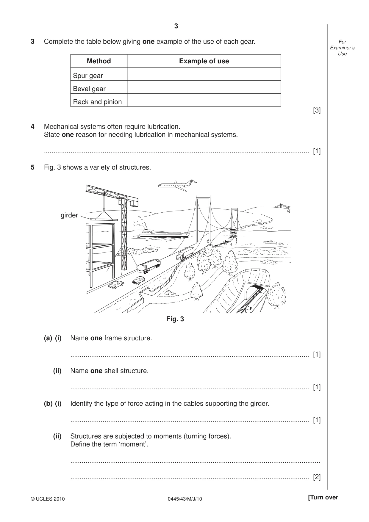
3 0445/43/M/J/10 © UCLES 2010 [Turn over For Examiner’s Use 3 Complete the table below giving one example of the use of each gear. Method Example of use Spur gear Bevel gear Rack and pinion [3] 4 Mechanical systems often require lubrication. State one reason for needing lubrication in mechanical systems. … [1] 5 Fig. 3 shows a variety of structures. Fig. 3 girder (a) (i) Name one frame structure. … [1] (ii) Name one shell structure. … [1] (b) (i) Identify the type of force acting in the cables supporting the girder. … [1] (ii) Structures are subjected to moments (turning forces). Defi ne the term ‘moment’. … … [2]
Question paper, page 4
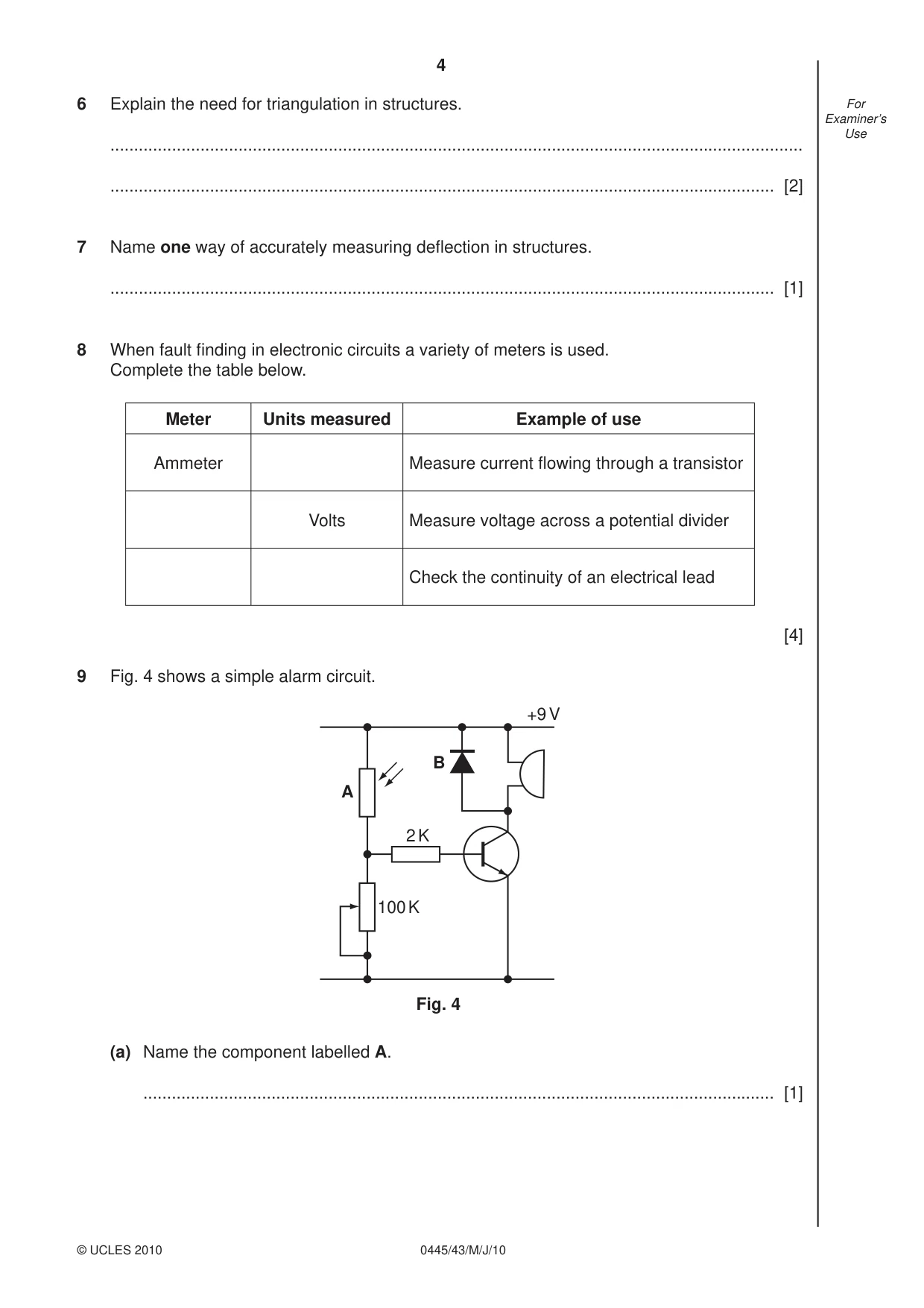
4 0445/43/M/J/10 © UCLES 2010 For Examiner’s Use 6 Explain the need for triangulation in structures. … … [2] 7 Name one way of accurately measuring defl ection in structures. … [1] 8 When fault fi nding in electronic circuits a variety of meters is used. Complete the table below. Meter Units measured Example of use Ammeter Measure current fl owing through a transistor Volts Measure voltage across a potential divider Check the continuity of an electrical lead [4] 9 Fig. 4 shows a simple alarm circuit. 2 K 100 K +9 V Fig. 4 B A (a) Name the component labelled A. … [1]
Question paper, page 5
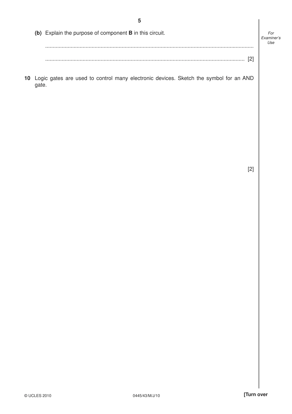
5 0445/43/M/J/10 © UCLES 2010 [Turn over For Examiner’s Use (b) Explain the purpose of component B in this circuit. … … [2] 10 Logic gates are used to control many electronic devices. Sketch the symbol for an AND gate. [2]
Question paper, page 6
6 0445/43/M/J/10 © UCLES 2010 For Examiner’s Use Section B Answer one question from this section. 11 (a) Complete Fig. 5 which shows a selection of switches. Type Appearance Application [1] Non-contact operation by magnet for detecting the opening or closing of doors/windows Tilt [2] Membrane panel [3] Waterproof keypads Fig. 5 (b) A slide switch can be used to select different functions in a circuit. Draw and label a simple circuit diagram to show this operation. [3]
Question paper, page 7
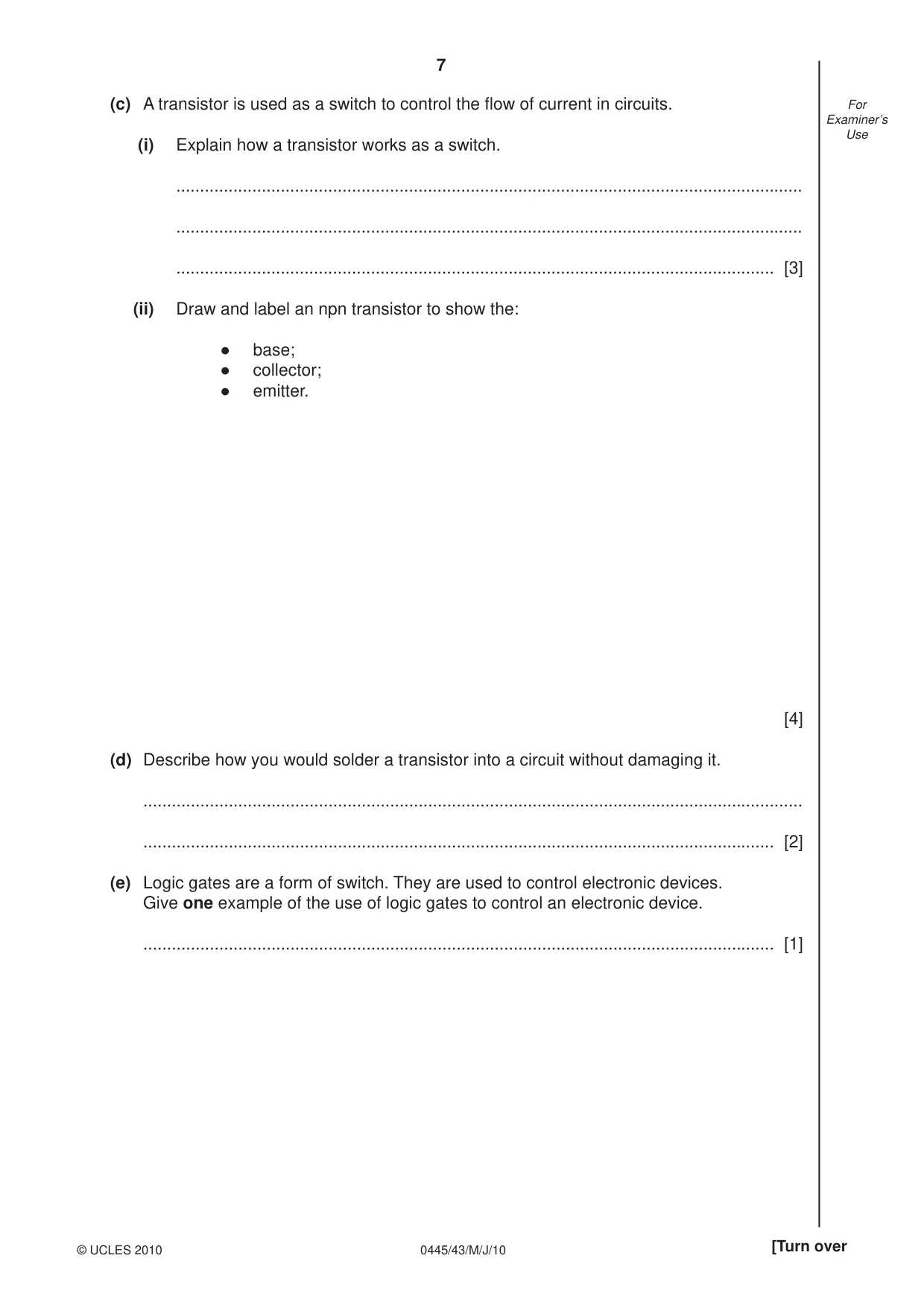
7 0445/43/M/J/10 © UCLES 2010 [Turn over For Examiner’s Use (c) A transistor is used as a switch to control the fl ow of current in circuits. (i) Explain how a transistor works as a switch. … … … [3] (ii) Draw and label an npn transistor to show the: ● base; ● collector; ● emitter. [4] (d) Describe how you would solder a transistor into a circuit without damaging it. … … [2] (e) Logic gates are a form of switch. They are used to control electronic devices. Give one example of the use of logic gates to control an electronic device. … [1]
Question paper, page 8
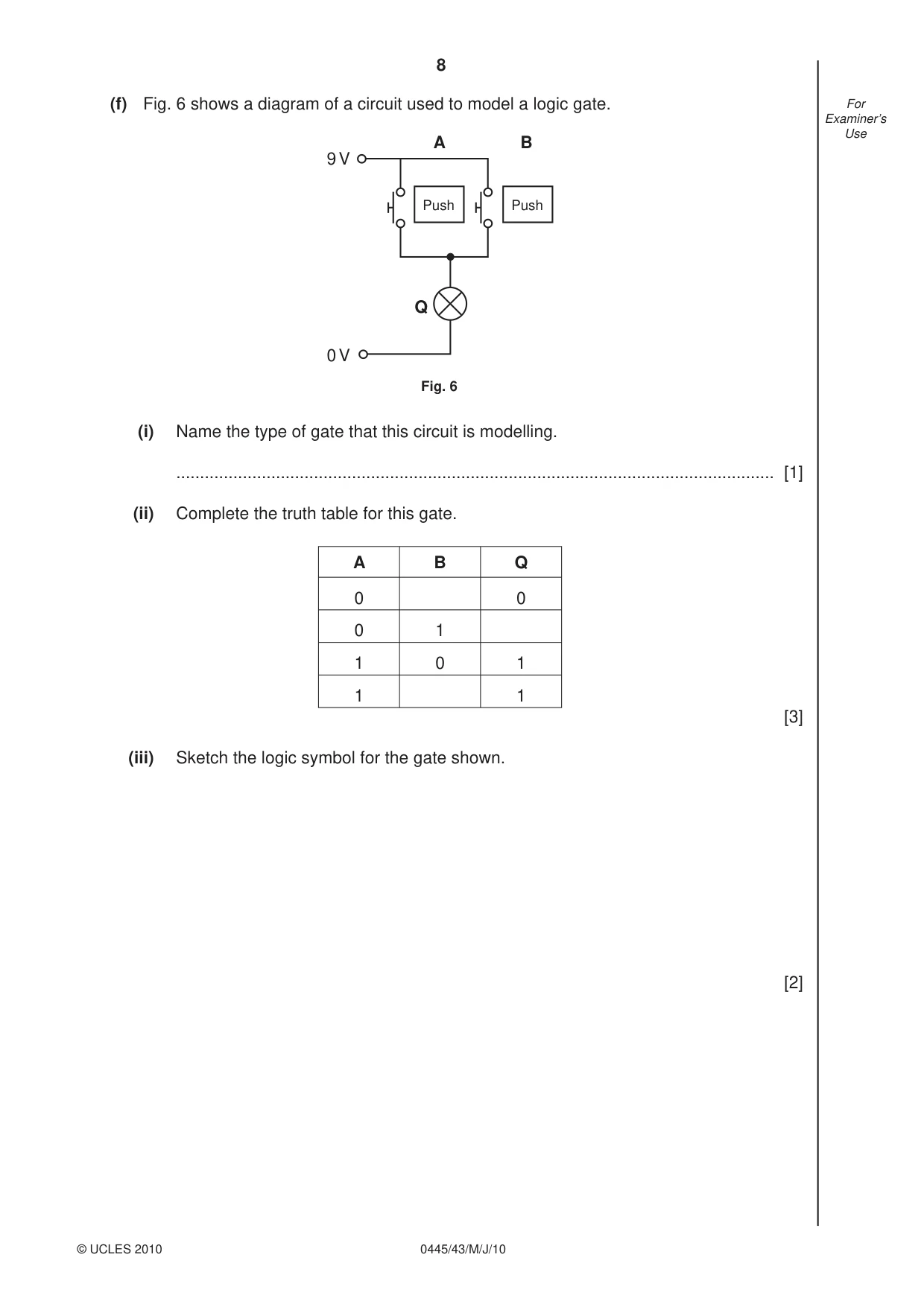
8 0445/43/M/J/10 © UCLES 2010 For Examiner’s Use (f) Fig. 6 shows a diagram of a circuit used to model a logic gate. Push Push A B Q Fig. 6 9 V 0 V (i) Name the type of gate that this circuit is modelling. … [1] (ii) Complete the truth table for this gate. A B Q 0 0 0 1 1 0 1 1 1 [3] (iii) Sketch the logic symbol for the gate shown. [2]
Question paper, page 9
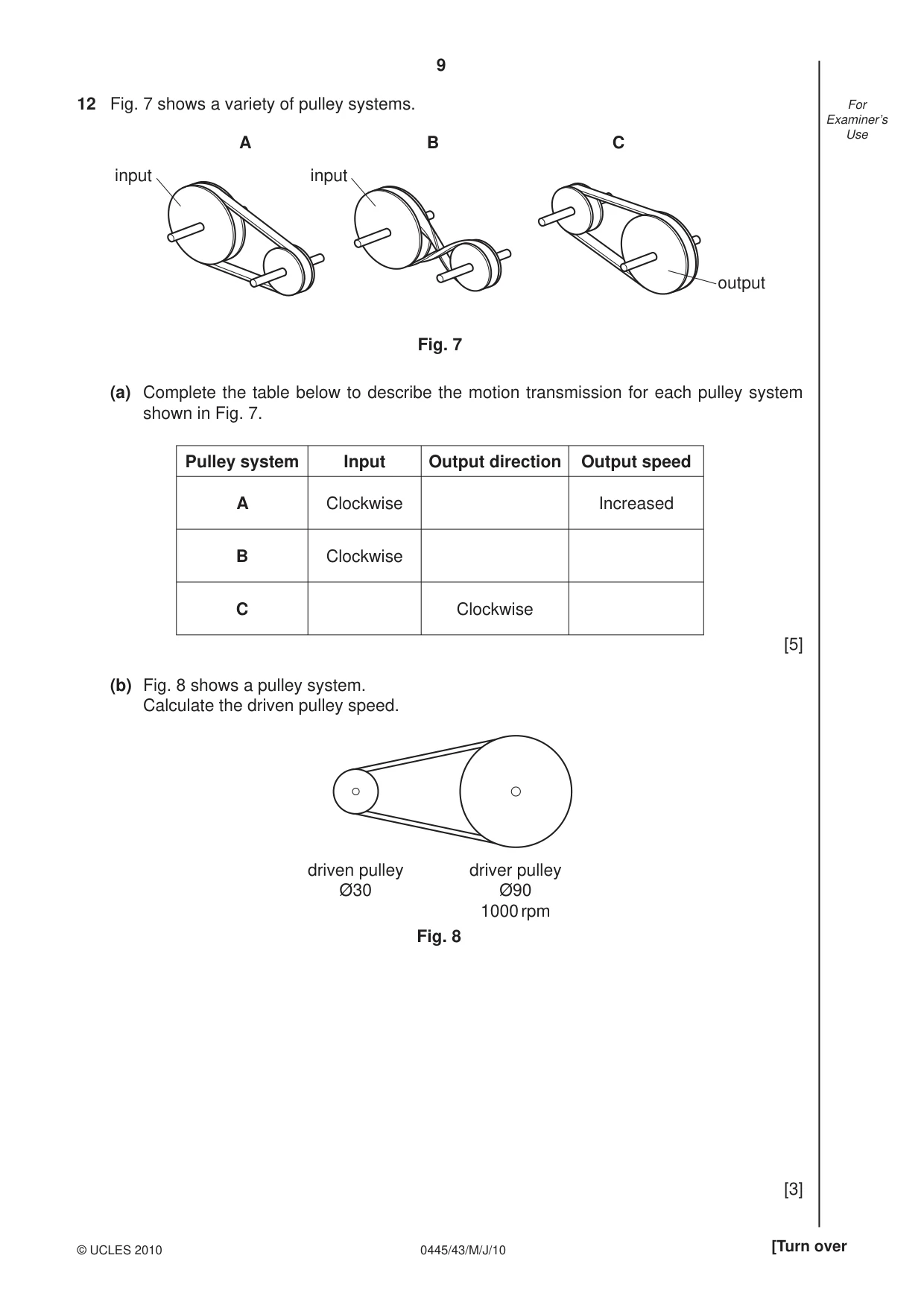
9 0445/43/M/J/10 © UCLES 2010 [Turn over For Examiner’s Use 12 Fig. 7 shows a variety of pulley systems. A B C input input output Fig. 7 (a) Complete the table below to describe the motion transmission for each pulley system shown in Fig. 7. Pulley system Input Output direction Output speed A Clockwise Increased B Clockwise C Clockwise [5] (b) Fig. 8 shows a pulley system. Calculate the driven pulley speed. driven pulley Ø30 driver pulley Ø90 1000 rpm Fig. 8 [3]
Question paper, page 10
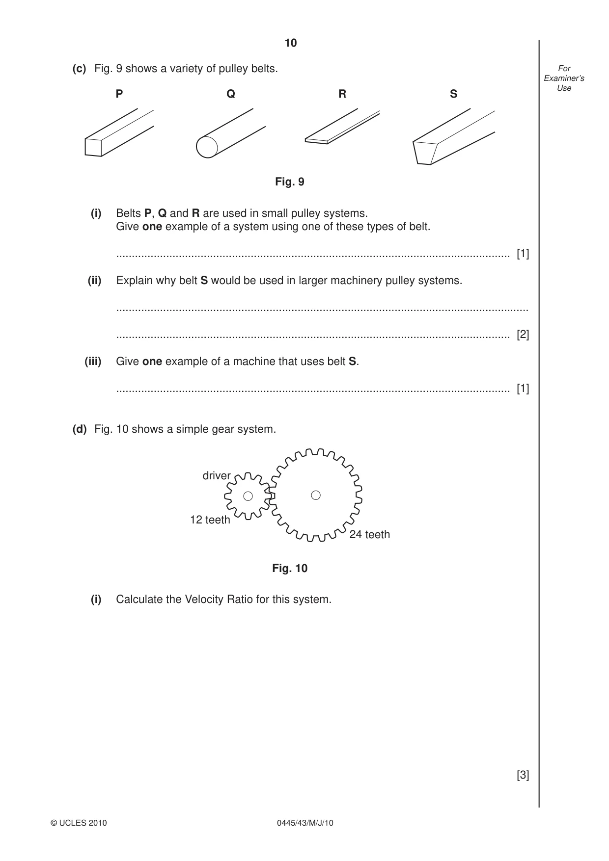
10 0445/43/M/J/10 © UCLES 2010 For Examiner’s Use (c) Fig. 9 shows a variety of pulley belts. P Q R S Fig. 9 (i) Belts P, Q and R are used in small pulley systems. Give one example of a system using one of these types of belt. … [1] (ii) Explain why belt S would be used in larger machinery pulley systems. … … [2] (iii) Give one example of a machine that uses belt S. … [1] (d) Fig. 10 shows a simple gear system. 12 teeth 24 teeth driver Fig. 10 (i) Calculate the Velocity Ratio for this system. [3]
Question paper, page 11
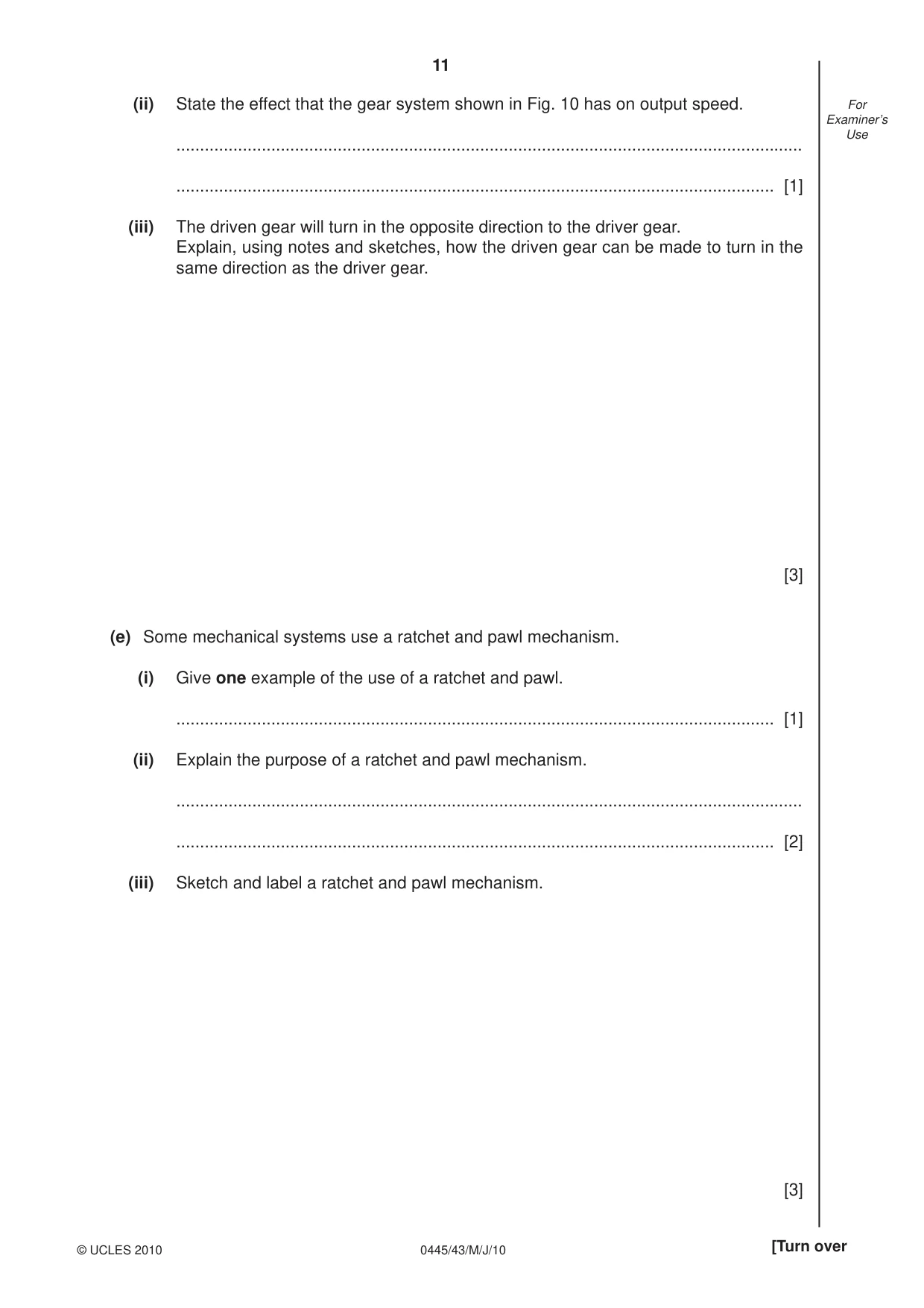
11 0445/43/M/J/10 © UCLES 2010 [Turn over For Examiner’s Use (ii) State the effect that the gear system shown in Fig. 10 has on output speed. … … [1] (iii) The driven gear will turn in the opposite direction to the driver gear. Explain, using notes and sketches, how the driven gear can be made to turn in the same direction as the driver gear. [3] (e) Some mechanical systems use a ratchet and pawl mechanism. (i) Give one example of the use of a ratchet and pawl. … [1] (ii) Explain the purpose of a ratchet and pawl mechanism. … … [2] (iii) Sketch and label a ratchet and pawl mechanism. [3]
Question paper, page 12
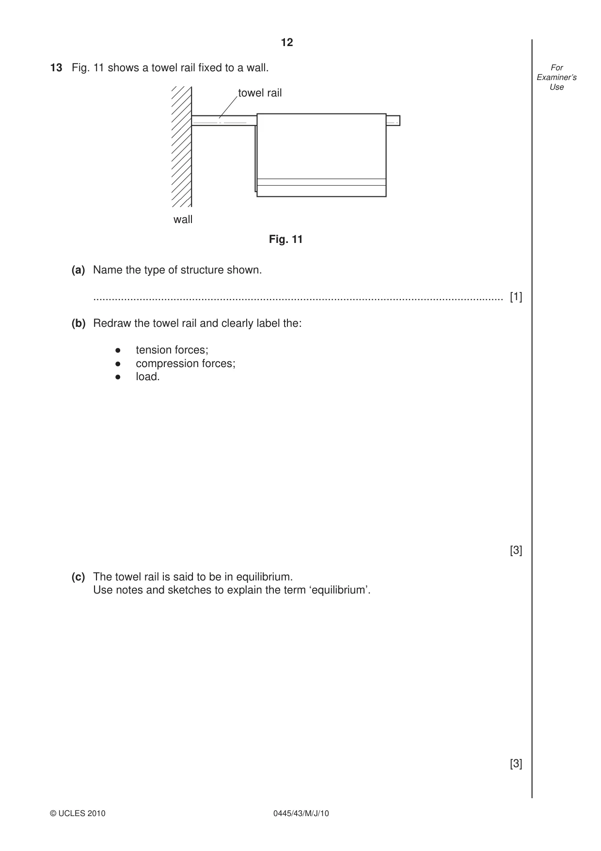
12 0445/43/M/J/10 © UCLES 2010 For Examiner’s Use 13 Fig. 11 shows a towel rail fi xed to a wall. towel rail wall Fig. 11 (a) Name the type of structure shown. … [1] (b) Redraw the towel rail and clearly label the: ● tension forces; ● compression forces; ● load. [3] (c) The towel rail is said to be in equilibrium. Use notes and sketches to explain the term ‘equilibrium’. [3]
Question paper, page 13
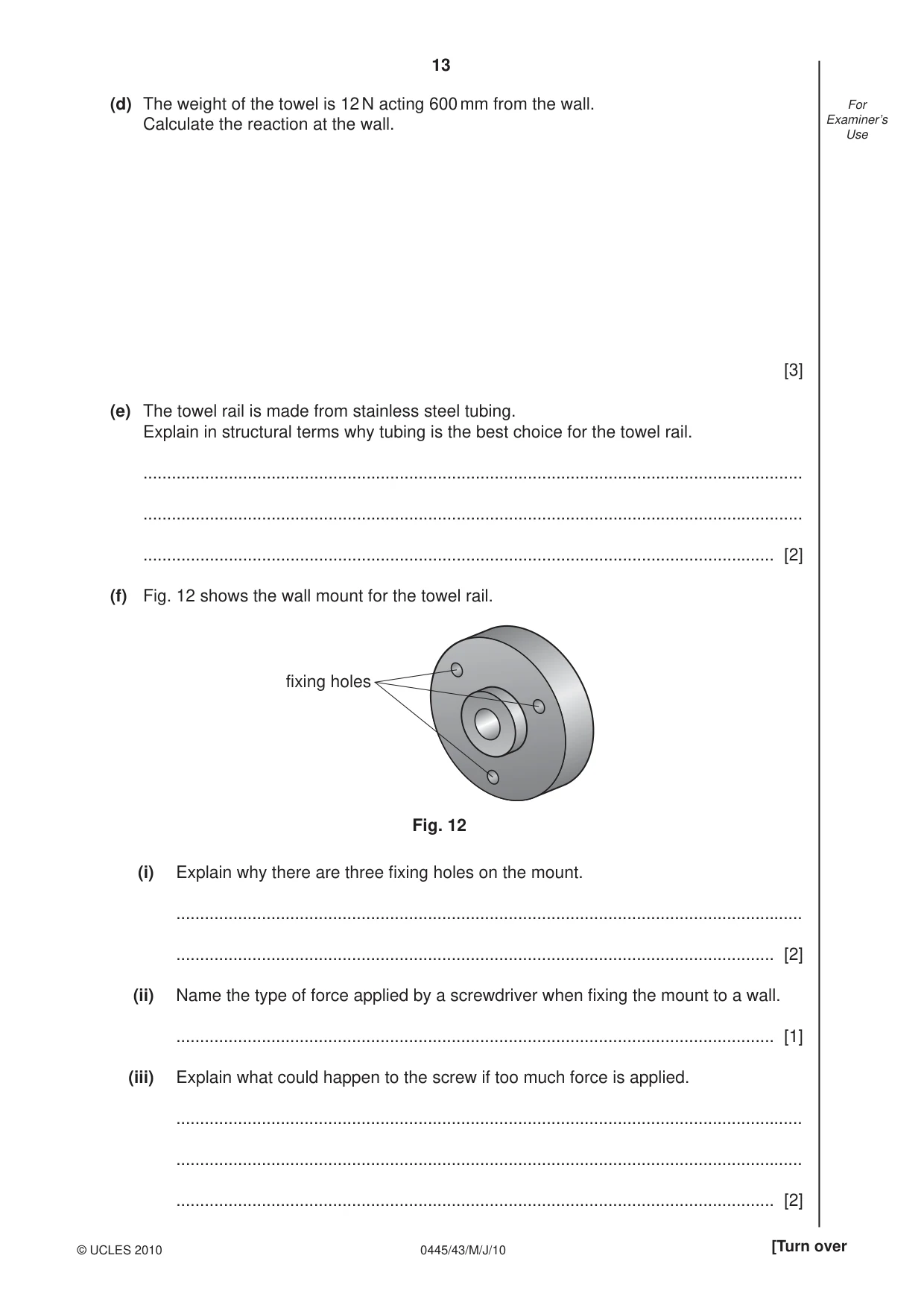
13 0445/43/M/J/10 © UCLES 2010 [Turn over For Examiner’s Use (d) The weight of the towel is 12 N acting 600 mm from the wall. Calculate the reaction at the wall. [3] (e) The towel rail is made from stainless steel tubing. Explain in structural terms why tubing is the best choice for the towel rail. … … … [2] (f) Fig. 12 shows the wall mount for the towel rail. fixing holes Fig. 12 (i) Explain why there are three fi xing holes on the mount. … … [2] (ii) Name the type of force applied by a screwdriver when fi xing the mount to a wall. … [1] (iii) Explain what could happen to the screw if too much force is applied. … … … [2]
Question paper, page 14
14 0445/43/M/J/10 © UCLES 2010 For Examiner’s Use (g) Fig. 13 shows a metal stepladder. tread rail legs Fig. 13 (i) Explain why the legs of the stepladder form a triangular shape when opened. … … … [2] (ii) Explain the purpose of the rail. … … … [2] (iii) Explain why the tread has folded edges. … … … [2]
Question paper, page 15
15 0445/43/M/J/10 © UCLES 2010 For Examiner’s Use (iv) Use notes and sketches to show the effect of loading on one of the stepladder treads. [2]
Question paper, page 16
16 0445/43/M/J/10 Permission to reproduce items where third-party owned material protected by copyright is included has been sought and cleared where possible. Every reasonable effort has been made by the publisher (UCLES) to trace copyright holders, but if any items requiring clearance have unwittingly been included the publisher will be pleased to make amends at the earliest possible opportunity. University of Cambridge International Examinations is part of the Cambridge Assessment Group. Cambridge Assessment is the brand name of University of Cambridge Local Examinations Syndicate (UCLES), which is itself a department of the University of Cambridge. BLANK PAGE © UCLES 2010
What you needed in this session
Cambridge’s own grade thresholds for 2010 May/June, Paper 4 · Variant 3. A higher threshold means an easier paper — the bar moves with how the cohort did.