Cambridge IGCSE Design and Technology 0445 — 2009 Oct/Nov Paper 4 · Variant 1
0445/41/O/N/09 · 50 marks · ≈56 min
The question paper and its mark scheme, free to read here and free to download. This is Cambridge’s own paper, exactly as it was sat.
Question paper16 pages

Mark scheme8 pages
Answers below. Sit the paper first if you are practising.
Paper as text
Question paper, page 1
[Turn over *7123512061* READ THESE INSTRUCTIONS FIRST Write your Centre number, candidate number and name on all the work you hand in. Write in dark blue or black pen. You may use a soft pencil for any diagrams or graphs. Do not use staples, paper clips, highlighters, glue or correction fl uid. DO NOT WRITE IN ANY BARCODES. You may use a calculator. Section A Answer all questions. Section B Answer one question. At the end of the examination, fasten all your work securely together. The number of marks is given in brackets [ ] at the end of each question or part question. For Examiner’s Use Section A Section B Total DESIGN AND TECHNOLOGY 0445/04 Paper 4 Systems and Control October/November 2009 1 hour Candidates answer on the Question Paper. No Additional Materials are required. To be taken together with Paper 1 in one session of 2 hours and 15 minutes. UNIVERSITY OF CAMBRIDGE INTERNATIONAL EXAMINATIONS International General Certifi cate of Secondary Education This document consists of an 15 printed pages and 1 blank page. [Turn over IB09 11_0445_04/2RP © UCLES 2009 www.XtremePapers.com
Question paper, page 2
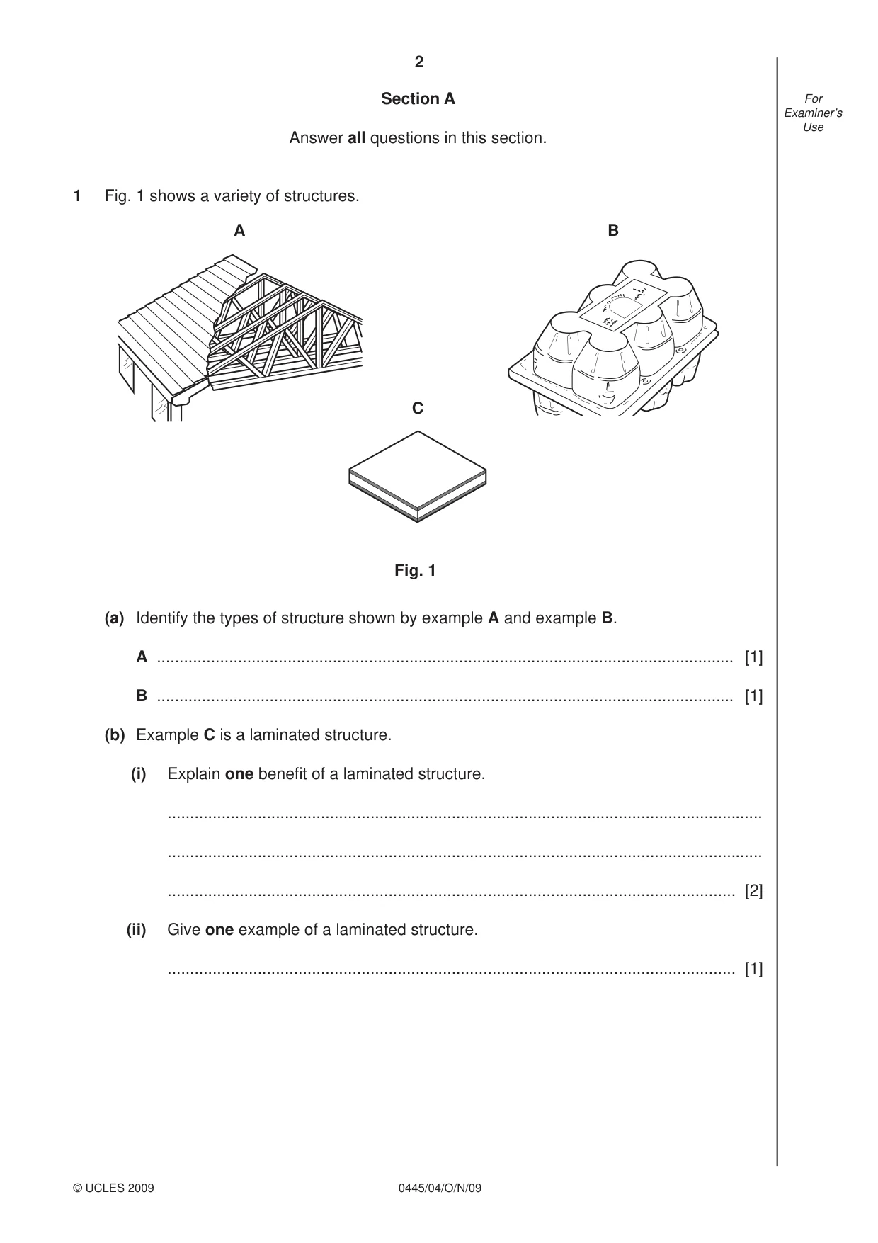
2 0445/04/O/N/09 © UCLES 2009 For Examiner’s Use Section A Answer all questions in this section. 1 Fig. 1 shows a variety of structures. A B C Fig. 1 (a) Identify the types of structure shown by example A and example B. A … [1] B … [1] (b) Example C is a laminated structure. (i) Explain one benefi t of a laminated structure. … … … [2] (ii) Give one example of a laminated structure. … [1]
Question paper, page 3
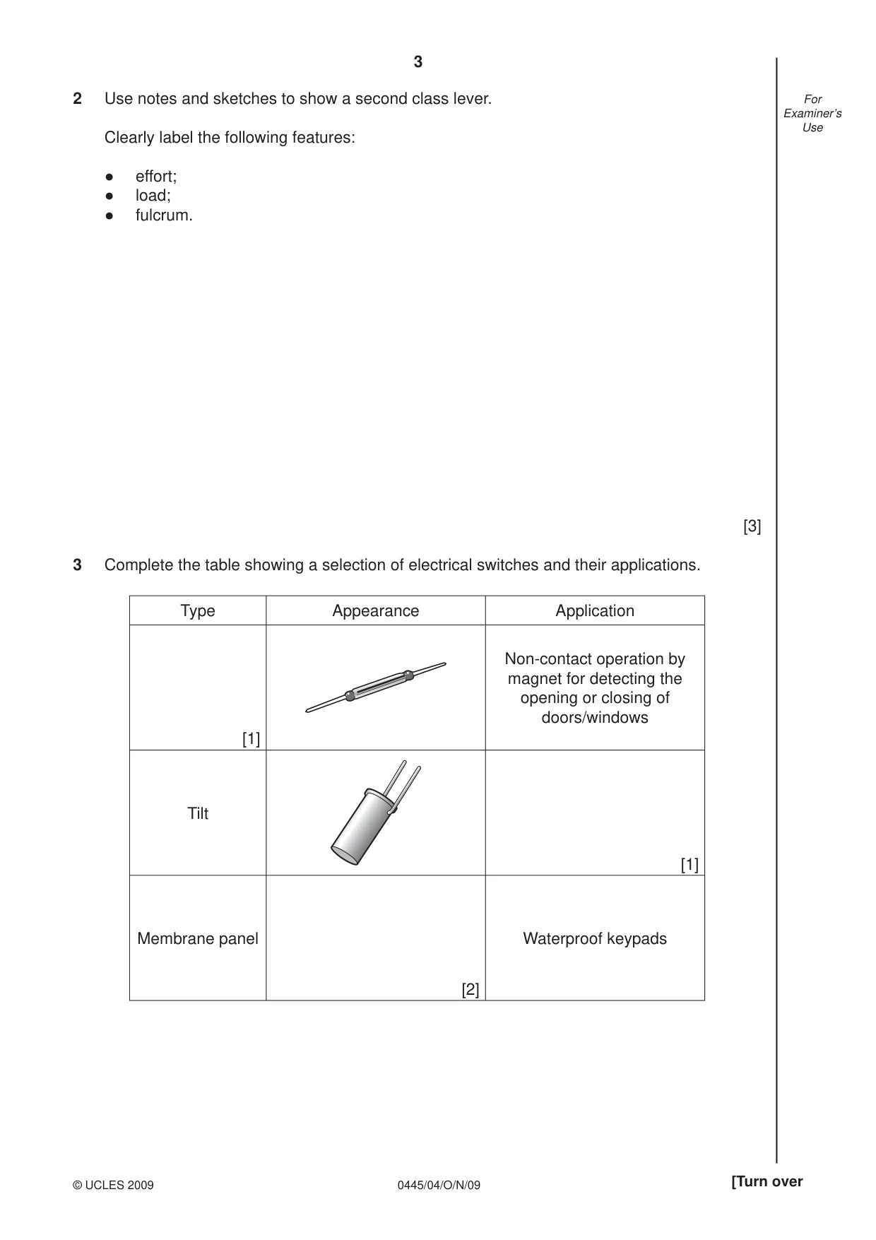
3 0445/04/O/N/09 © UCLES 2009 [Turn over For Examiner’s Use 2 Use notes and sketches to show a second class lever. Clearly label the following features: ● effort; ● load; ● fulcrum. [3] 3 Complete the table showing a selection of electrical switches and their applications. Type Appearance Application [1] Non-contact operation by magnet for detecting the opening or closing of doors/windows Tilt [1] Membrane panel [2] Waterproof keypads
Question paper, page 4
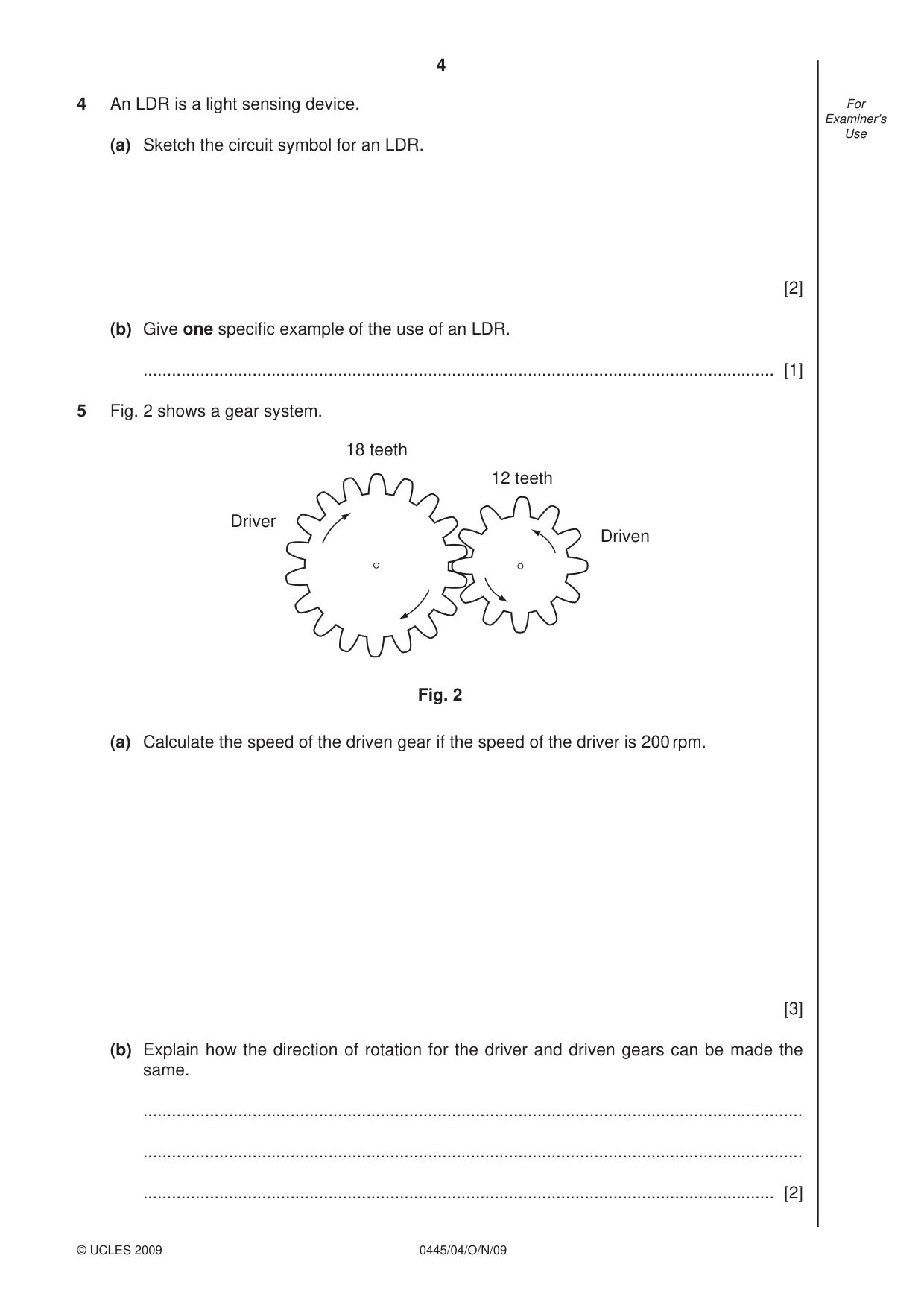
4 0445/04/O/N/09 © UCLES 2009 For Examiner’s Use 4 An LDR is a light sensing device. (a) Sketch the circuit symbol for an LDR. [2] (b) Give one specifi c example of the use of an LDR. … [1] 5 Fig. 2 shows a gear system. Driver 18 teeth 12 teeth Driven Fig. 2 (a) Calculate the speed of the driven gear if the speed of the driver is 200 rpm. [3] (b) Explain how the direction of rotation for the driver and driven gears can be made the same. … … … [2]
Question paper, page 5
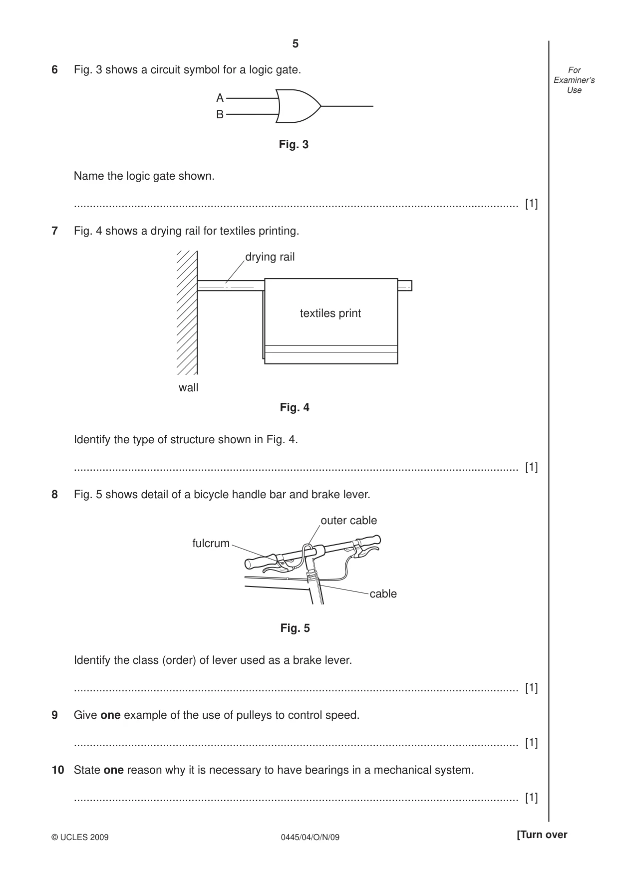
5 0445/04/O/N/09 © UCLES 2009 [Turn over For Examiner’s Use 6 Fig. 3 shows a circuit symbol for a logic gate. A B Fig. 3 Name the logic gate shown. … [1] 7 Fig. 4 shows a drying rail for textiles printing. drying rail wall textiles print Fig. 4 Identify the type of structure shown in Fig. 4. … [1] 8 Fig. 5 shows detail of a bicycle handle bar and brake lever. Fig. 5 fulcrum cable outer cable Identify the class (order) of lever used as a brake lever. … [1] 9 Give one example of the use of pulleys to control speed. … [1] 10 State one reason why it is necessary to have bearings in a mechanical system. … [1]
Question paper, page 6
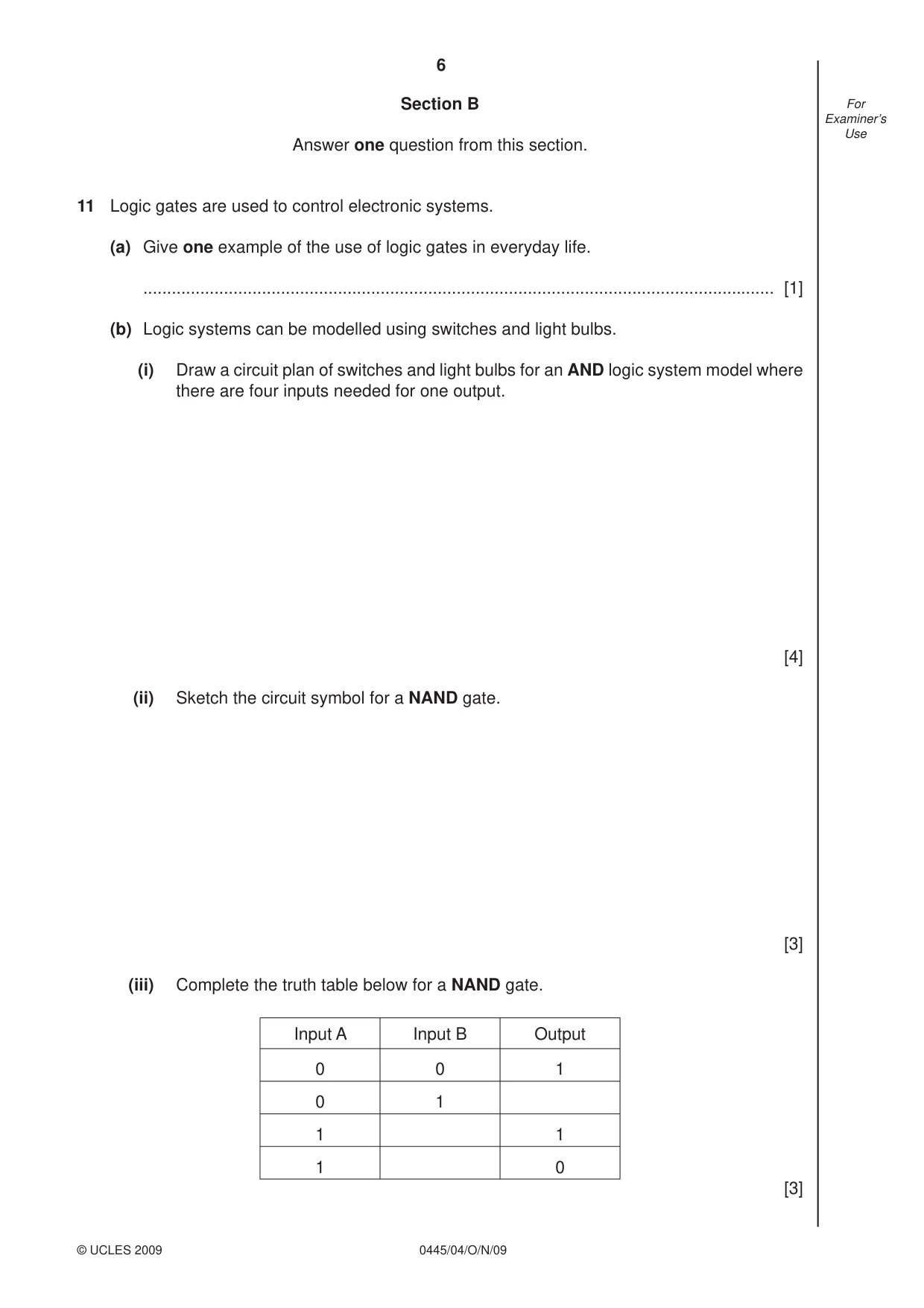
6 0445/04/O/N/09 © UCLES 2009 For Examiner’s Use Section B Answer one question from this section. 11 Logic gates are used to control electronic systems. (a) Give one example of the use of logic gates in everyday life. … [1] (b) Logic systems can be modelled using switches and light bulbs. (i) Draw a circuit plan of switches and light bulbs for an AND logic system model where there are four inputs needed for one output. [4] (ii) Sketch the circuit symbol for a NAND gate. [3] (iii) Complete the truth table below for a NAND gate. Input A Input B Output 0 0 1 0 1 1 1 1 0 [3]
Question paper, page 7
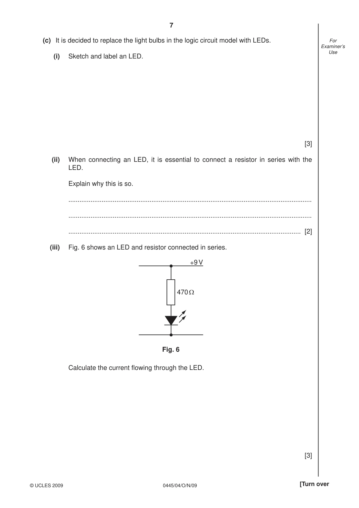
7 0445/04/O/N/09 © UCLES 2009 [Turn over For Examiner’s Use (c) It is decided to replace the light bulbs in the logic circuit model with LEDs. (i) Sketch and label an LED. [3] (ii) When connecting an LED, it is essential to connect a resistor in series with the LED. Explain why this is so. … … … [2] (iii) Fig. 6 shows an LED and resistor connected in series. 470 Ω +9 V Fig. 6 Calculate the current fl owing through the LED. [3]
Question paper, page 8
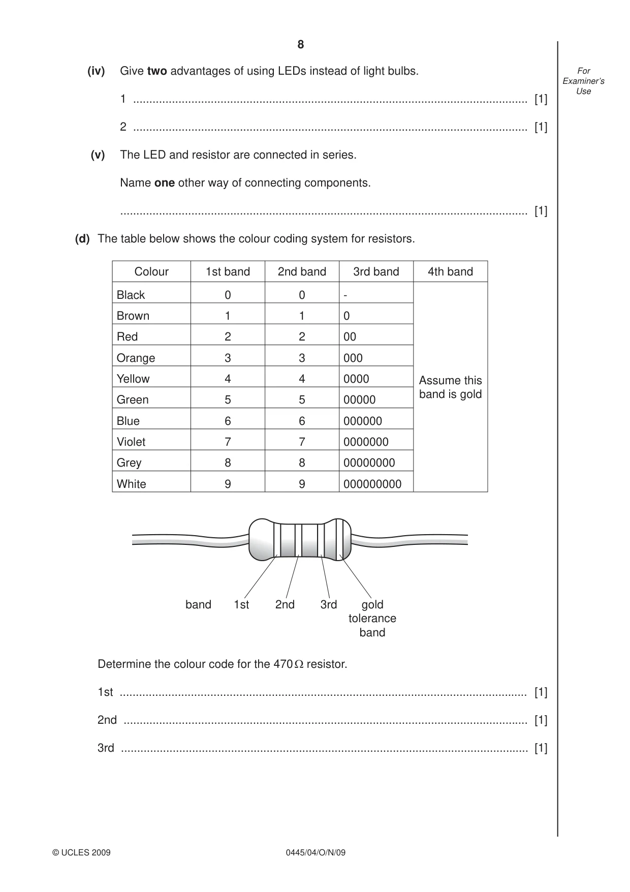
8 0445/04/O/N/09 © UCLES 2009 For Examiner’s Use (iv) Give two advantages of using LEDs instead of light bulbs. 1 … [1] 2 … [1] (v) The LED and resistor are connected in series. Name one other way of connecting components. … [1] (d) The table below shows the colour coding system for resistors. Colour 1st band 2nd band 3rd band 4th band Black 0 0 - Assume this band is gold Brown 1 1 0 Red 2 2 00 Orange 3 3 000 Yellow 4 4 0000 Green 5 5 00000 Blue 6 6 000000 Violet 7 7 0000000 Grey 8 8 00000000 White 9 9 000000000 1st band 2nd 3rd gold tolerance band Determine the colour code for the 470 Ω resistor. 1st … [1] 2nd … [1] 3rd … [1]
Question paper, page 9
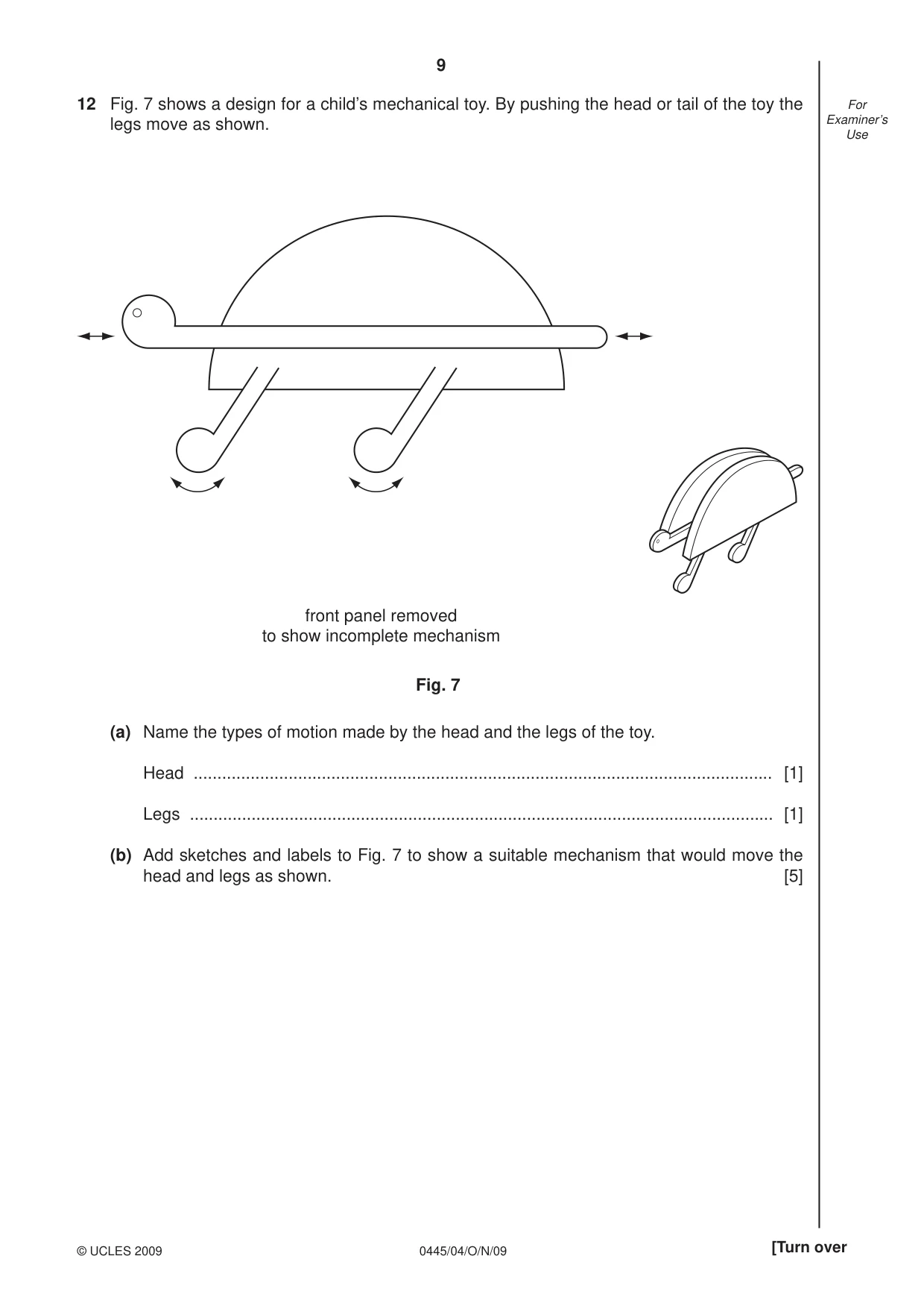
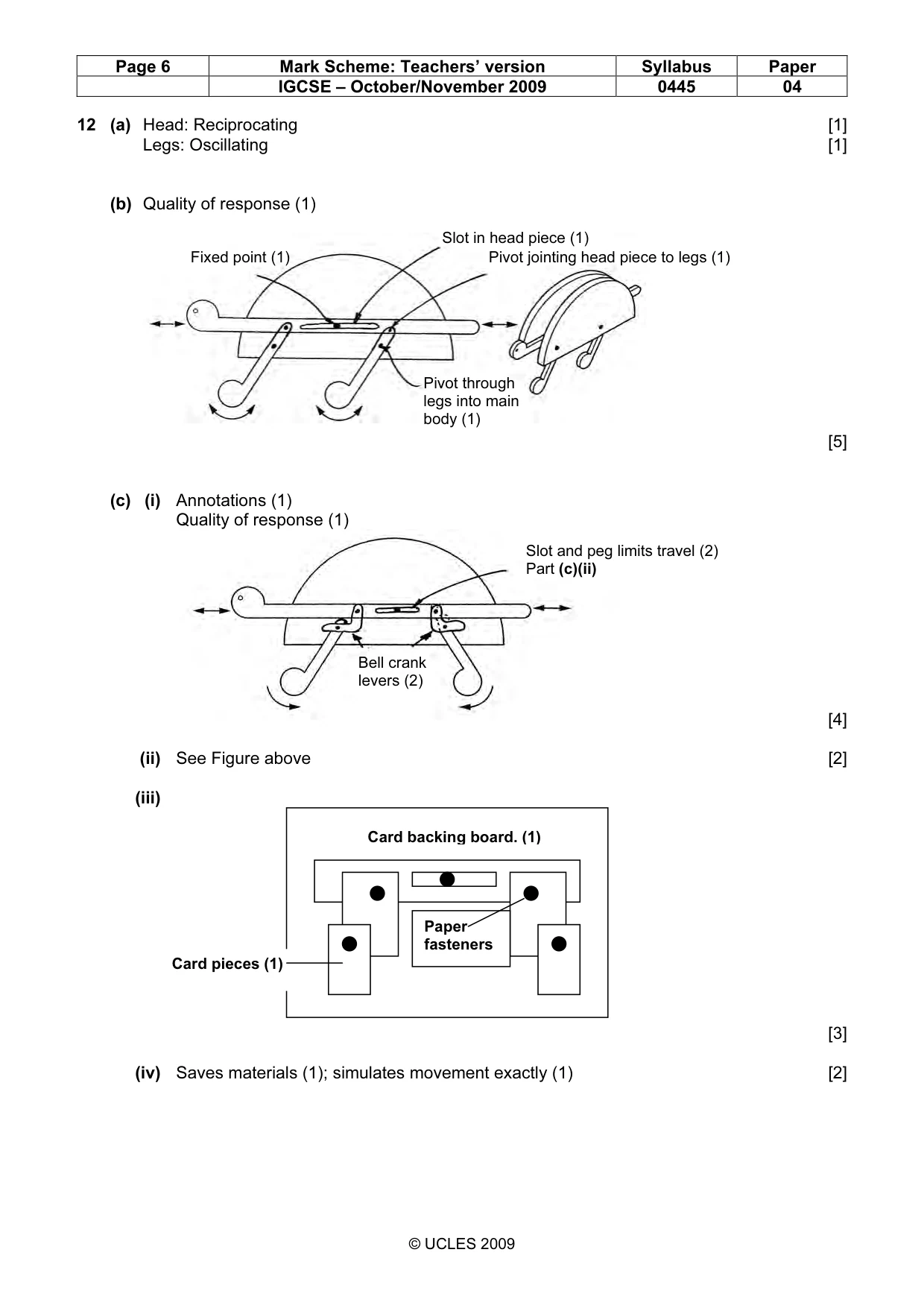
9 0445/04/O/N/09 © UCLES 2009 [Turn over For Examiner’s Use 12 Fig. 7 shows a design for a child’s mechanical toy. By pushing the head or tail of the toy the legs move as shown. front panel removed to show incomplete mechanism Fig. 7 (a) Name the types of motion made by the head and the legs of the toy. Head … [1] Legs … [1] (b) Add sketches and labels to Fig. 7 to show a suitable mechanism that would move the head and legs as shown. [5]
Question paper, page 10
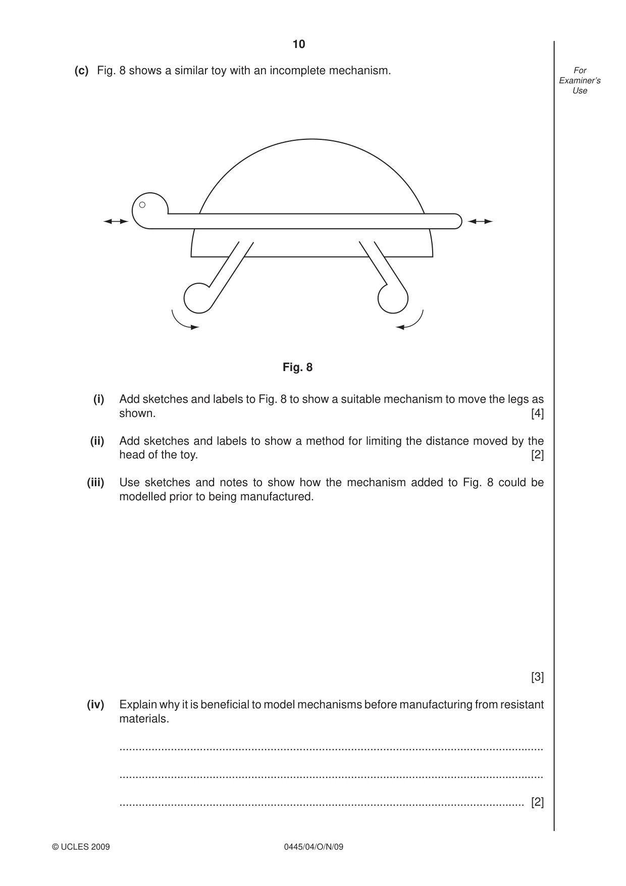
10 0445/04/O/N/09 © UCLES 2009 For Examiner’s Use (c) Fig. 8 shows a similar toy with an incomplete mechanism. Fig. 8 (i) Add sketches and labels to Fig. 8 to show a suitable mechanism to move the legs as shown. [4] (ii) Add sketches and labels to show a method for limiting the distance moved by the head of the toy. [2] (iii) Use sketches and notes to show how the mechanism added to Fig. 8 could be modelled prior to being manufactured. [3] (iv) Explain why it is benefi cial to model mechanisms before manufacturing from resistant materials. … … … [2]
Question paper, page 11
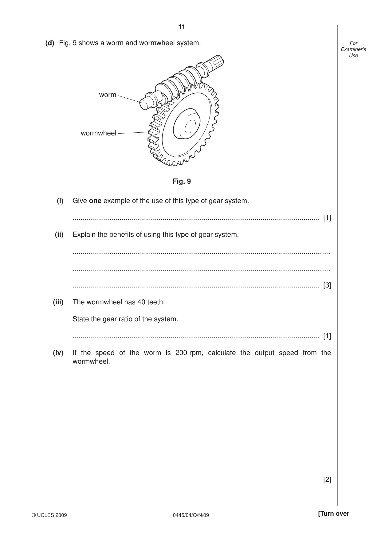
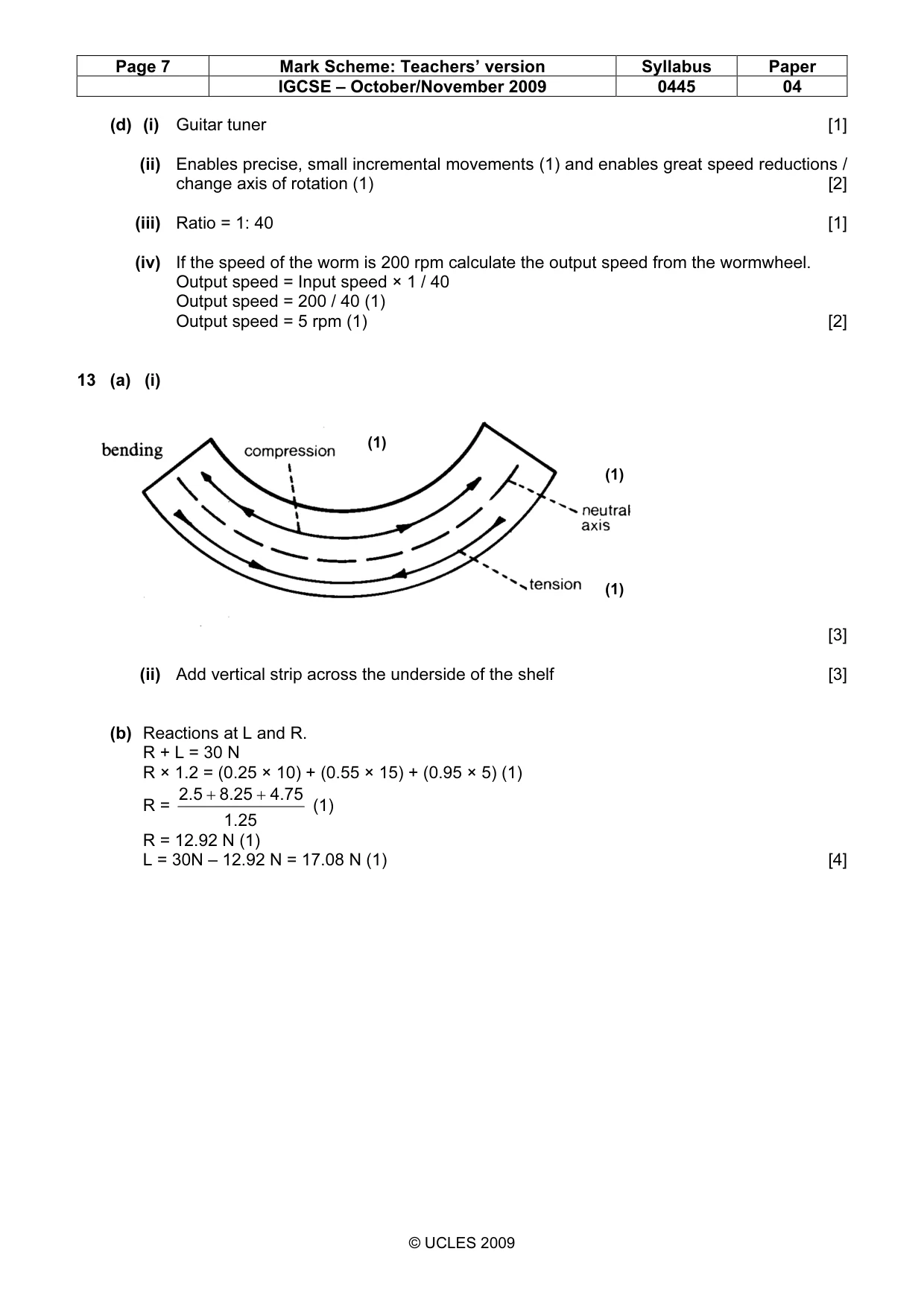
11 0445/04/O/N/09 © UCLES 2009 [Turn over For Examiner’s Use (d) Fig. 9 shows a worm and wormwheel system. worm wormwheel Fig. 9 (i) Give one example of the use of this type of gear system. … [1] (ii) Explain the benefi ts of using this type of gear system. … … … [3] (iii) The wormwheel has 40 teeth. State the gear ratio of the system. … [1] (iv) If the speed of the worm is 200 rpm, calculate the output speed from the wormwheel. [2]
Question paper, page 12
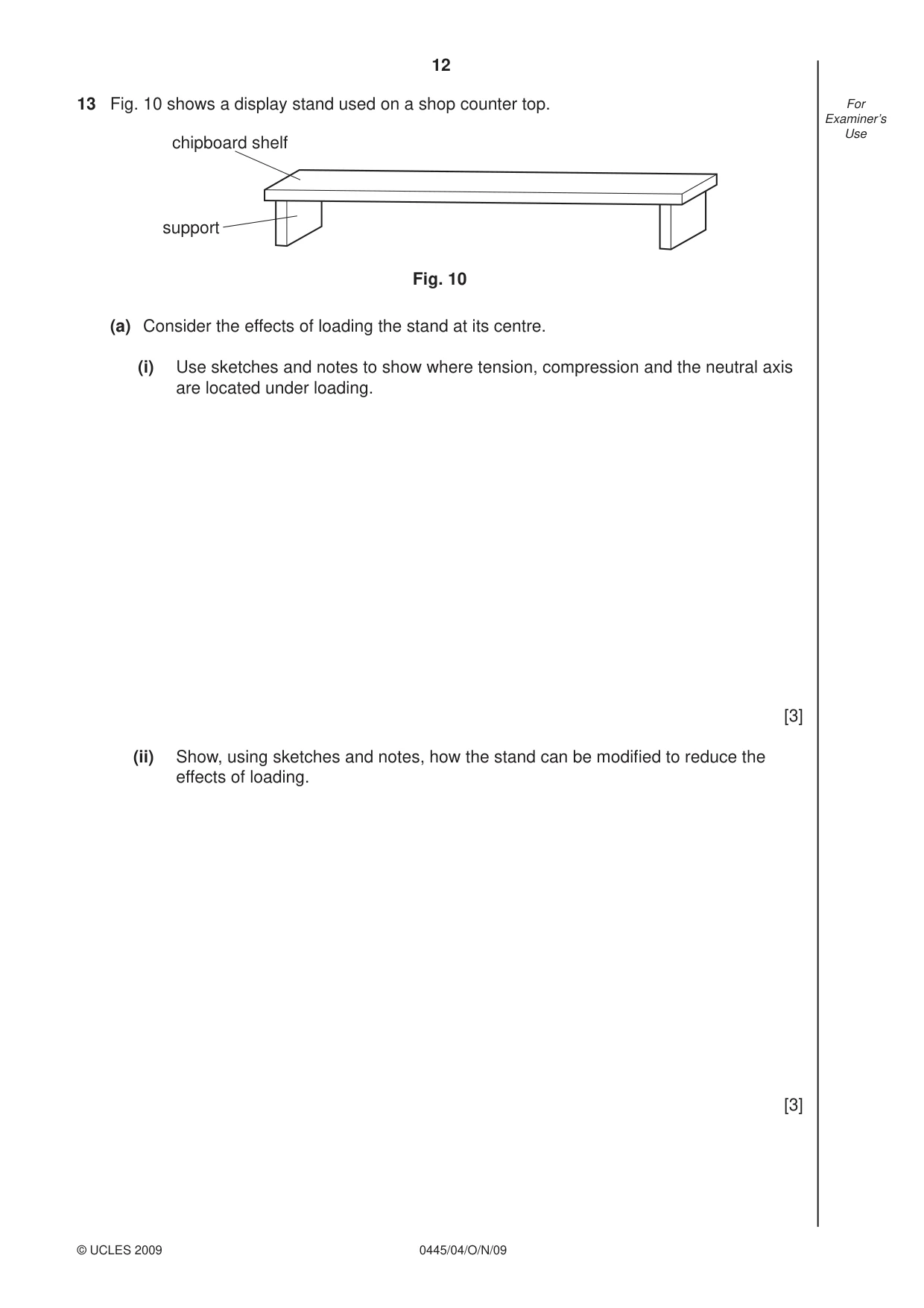
12 0445/04/O/N/09 © UCLES 2009 For Examiner’s Use 13 Fig. 10 shows a display stand used on a shop counter top. chipboard shelf support Fig. 10 (a) Consider the effects of loading the stand at its centre. (i) Use sketches and notes to show where tension, compression and the neutral axis are located under loading. [3] (ii) Show, using sketches and notes, how the stand can be modifi ed to reduce the effects of loading. [3]
Question paper, page 13
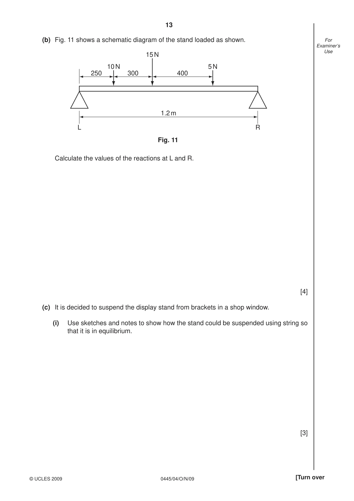
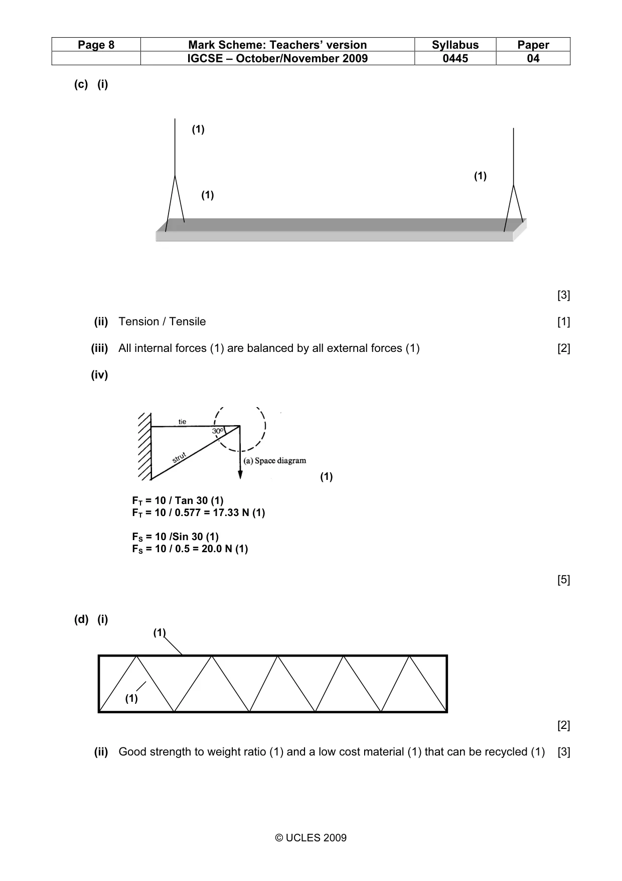
13 0445/04/O/N/09 © UCLES 2009 [Turn over For Examiner’s Use (b) Fig. 11 shows a schematic diagram of the stand loaded as shown. 250 300 400 1.2 m L R 10 N 5 N 15 N Fig. 11 Calculate the values of the reactions at L and R. [4] (c) It is decided to suspend the display stand from brackets in a shop window. (i) Use sketches and notes to show how the stand could be suspended using string so that it is in equilibrium. [3]
Question paper, page 14
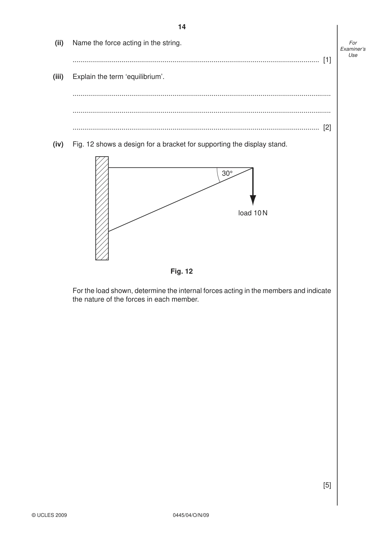
14 0445/04/O/N/09 © UCLES 2009 For Examiner’s Use (ii) Name the force acting in the string. … [1] (iii) Explain the term ‘equilibrium’. … … … [2] (iv) Fig. 12 shows a design for a bracket for supporting the display stand. load 10 N 30° Fig. 12 For the load shown, determine the internal forces acting in the members and indicate the nature of the forces in each member. [5]
Question paper, page 15
15 0445/04/O/N/09 © UCLES 2009 For Examiner’s Use (d) It is decided to replace the stand with a temporary structure made from corrugated cardboard. (i) Sketch and label a cross sectional view of corrugated cardboard. [2] (ii) Explain the structural benefi ts of using corrugated cardboard for temporary structures. … … … … … [2]
Question paper, page 16
16 0445/04/O/N/09 Permission to reproduce items where third-party owned material protected by copyright is included has been sought and cleared where possible. Every reasonable effort has been made by the publisher (UCLES) to trace copyright holders, but if any items requiring clearance have unwittingly been included the publisher will be pleased to make amends at the earliest possible opportunity. University of Cambridge International Examinations is part of the Cambridge Assessment Group. Cambridge Assessment is the brand name of University of Cambridge Local Examinations Syndicate (UCLES), which is itself a department of the University of Cambridge. BLANK PAGE
Mark scheme, page 1
UNIVERSITY OF CAMBRIDGE INTERNATIONAL EXAMINATIONS International General Certificate of Secondary Education MARK SCHEME for the October/November 2009 question paper for the guidance of teachers 0445 DESIGN AND TECHNOLOGY 0445/04 Paper 4 (Technology), maximum raw mark 50 This mark scheme is published as an aid to teachers and candidates, to indicate the requirements of the examination. It shows the basis on which Examiners were instructed to award marks. It does not indicate the details of the discussions that took place at an Examiners’ meeting before marking began, which would have considered the acceptability of alternative answers. Mark schemes must be read in conjunction with the question papers and the report on the examination. • CIE will not enter into discussions or correspondence in connection with these mark schemes. CIE is publishing the mark schemes for the October/November 2009 question papers for most IGCSE, GCE Advanced Level and Advanced Subsidiary Level syllabuses and some Ordinary Level syllabuses. www.XtremePapers.com
Mark scheme, page 2
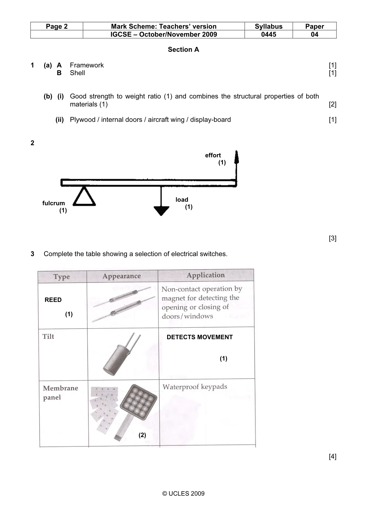
Page 2 Mark Scheme: Teachers’ version Syllabus Paper IGCSE – October/November 2009 0445 04 © UCLES 2009 Section A 1 (a) A Framework [1] B Shell [1] (b) (i) Good strength to weight ratio (1) and combines the structural properties of both materials (1) [2] (ii) Plywood / internal doors / aircraft wing / display-board [1] 2 [3] 3 Complete the table showing a selection of electrical switches. [4] REED (1) DETECTS MOVEMENT (1) fulcrum (1) (2) load (1) effort (1)
Mark scheme, page 3
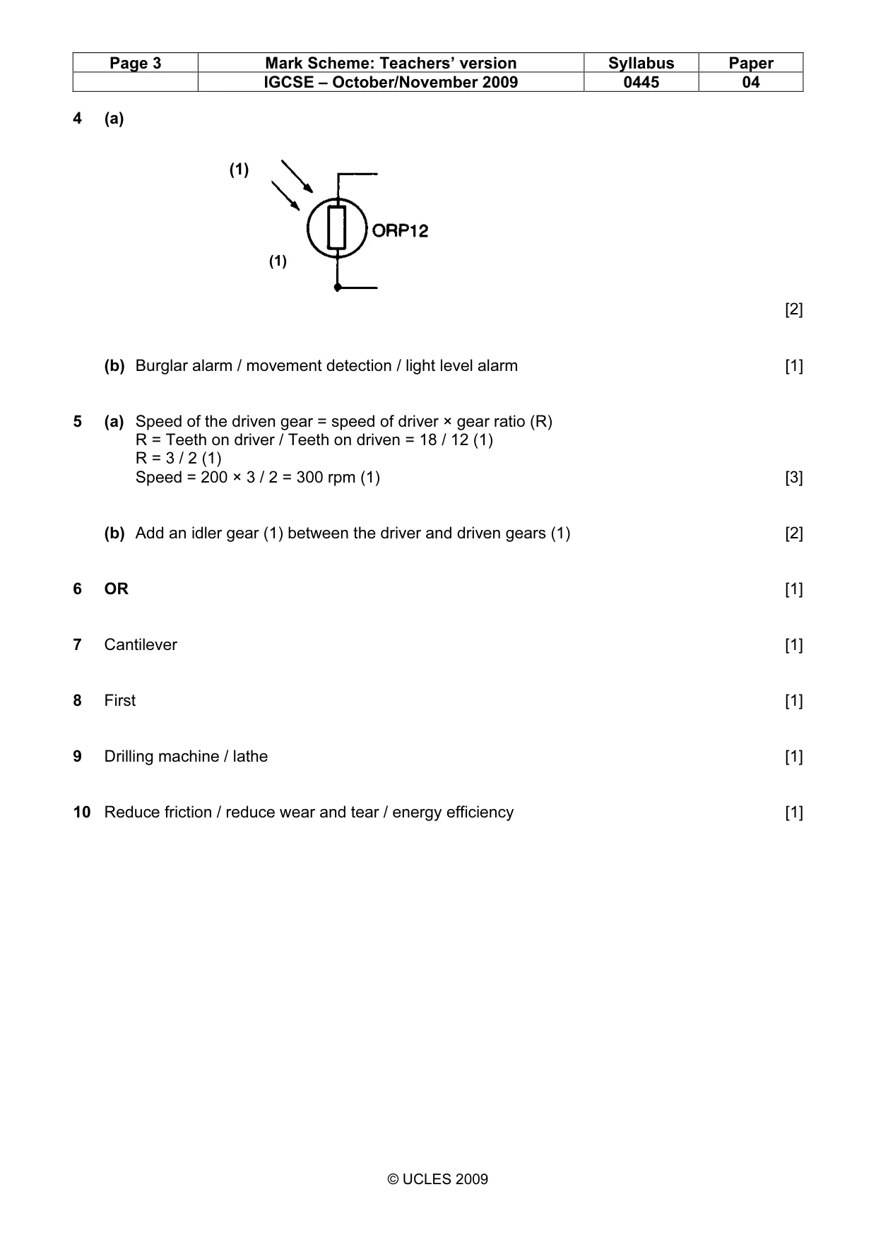
Page 3 Mark Scheme: Teachers’ version Syllabus Paper IGCSE – October/November 2009 0445 04 © UCLES 2009 4 (a) [2] (b) Burglar alarm / movement detection / light level alarm [1] 5 (a) Speed of the driven gear = speed of driver × gear ratio (R) R = Teeth on driver / Teeth on driven = 18 / 12 (1) R = 3 / 2 (1) Speed = 200 × 3 / 2 = 300 rpm (1) [3] (b) Add an idler gear (1) between the driver and driven gears (1) [2] 6 OR [1] 7 Cantilever [1] 8 First [1] 9 Drilling machine / lathe [1] 10 Reduce friction / reduce wear and tear / energy efficiency [1] (1) (1)
Mark scheme, page 4
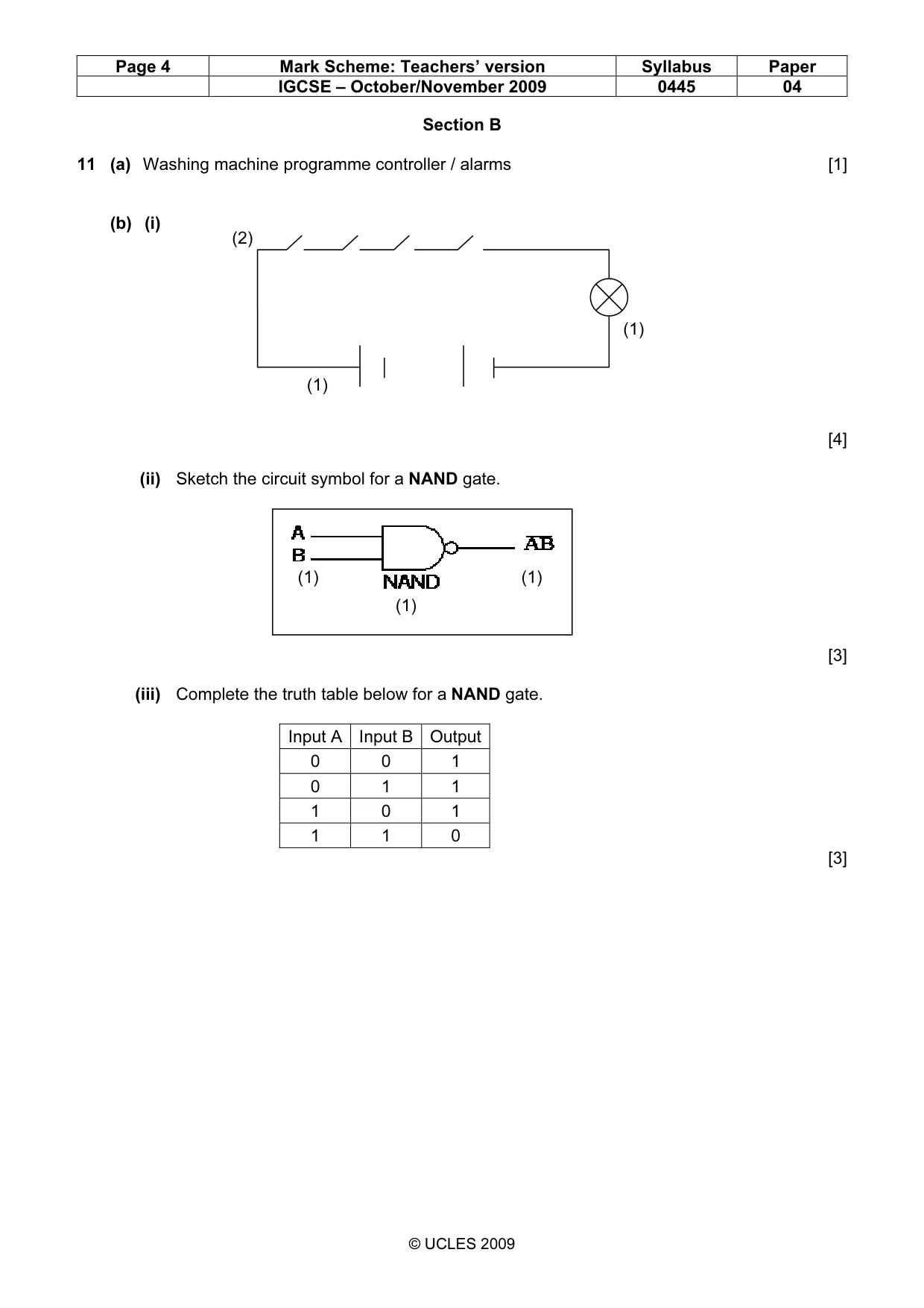
Page 4 Mark Scheme: Teachers’ version Syllabus Paper IGCSE – October/November 2009 0445 04 © UCLES 2009 Section B 11 (a) Washing machine programme controller / alarms [1] (b) (i) [4] (ii) Sketch the circuit symbol for a NAND gate. [3] (iii) Complete the truth table below for a NAND gate. Input A Input B Output 0 0 1 0 1 1 1 0 1 1 1 0 [3] (1) (1) (1) (2) (1) (1)
Mark scheme, page 5
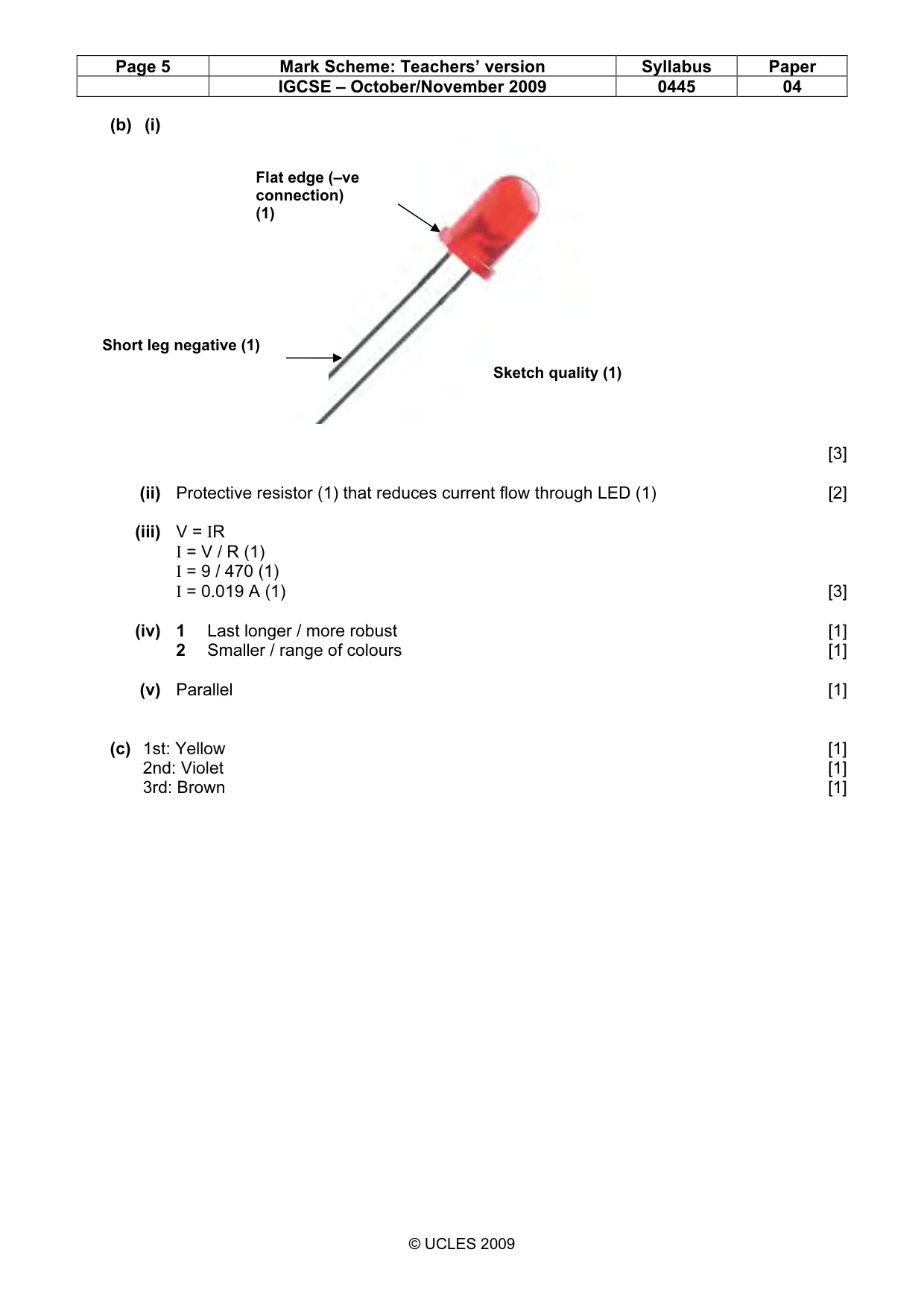
Page 5 Mark Scheme: Teachers’ version Syllabus Paper IGCSE – October/November 2009 0445 04 © UCLES 2009 (b) (i) [3] (ii) Protective resistor (1) that reduces current flow through LED (1) [2] (iii) V = IR I = V / R (1) I = 9 / 470 (1) I = 0.019 A (1) [3] (iv) 1 Last longer / more robust [1] 2 Smaller / range of colours [1] (v) Parallel [1] (c) 1st: Yellow [1] 2nd: Violet [1] 3rd: Brown [1] Flat edge (–ve connection) (1) Sketch quality (1) Short leg negative (1)
Mark scheme, page 6
Page 6 Mark Scheme: Teachers’ version Syllabus Paper IGCSE – October/November 2009 0445 04 © UCLES 2009 12 (a) Head: Reciprocating [1] Legs: Oscillating [1] (b) Quality of response (1) [5] (c) (i) Annotations (1) Quality of response (1) [4] (ii) See Figure above [2] (iii) [3] (iv) Saves materials (1); simulates movement exactly (1) [2] • Card backing board. (1) Card pieces (1) Paper fasteners Pivot through legs into main body (1) Pivot jointing head piece to legs (1) Slot in head piece (1) Fixed point (1) Bell crank levers (2) Slot and peg limits travel (2) Part (c)(ii)
Mark scheme, page 7
Page 7 Mark Scheme: Teachers’ version Syllabus Paper IGCSE – October/November 2009 0445 04 © UCLES 2009 (d) (i) Guitar tuner [1] (ii) Enables precise, small incremental movements (1) and enables great speed reductions / change axis of rotation (1) [2] (iii) Ratio = 1: 40 [1] (iv) If the speed of the worm is 200 rpm calculate the output speed from the wormwheel. Output speed = Input speed × 1 / 40 Output speed = 200 / 40 (1) Output speed = 5 rpm (1) [2] 13 (a) (i) [3] [3] (ii) Add vertical strip across the underside of the shelf [3] (b) Reactions at L and R. R + L = 30 N R × 1.2 = (0.25 × 10) + (0.55 × 15) + (0.95 × 5) (1) R = 1.25 4.75 8.25 2.5 + + (1) R = 12.92 N (1) L = 30N – 12.92 N = 17.08 N (1) [4] (1) (1) (1)
Mark scheme, page 8
Page 8 Mark Scheme: Teachers’ version Syllabus Paper IGCSE – October/November 2009 0445 04 © UCLES 2009 (c) (i) [3] (ii) Tension / Tensile [1] (iii) All internal forces (1) are balanced by all external forces (1) [2] (iv) [5] (d) (i) [2] (ii) Good strength to weight ratio (1) and a low cost material (1) that can be recycled (1) [3] (1) FT = 10 / Tan 30 (1) FT = 10 / 0.577 = 17.33 N (1) FS = 10 /Sin 30 (1) FS = 10 / 0.5 = 20.0 N (1) (1) (1) (1) (1) (1)
What you needed in this session
Cambridge’s own grade thresholds for 2009 Oct/Nov, Paper 4 · Variant 1. A higher threshold means an easier paper — the bar moves with how the cohort did.