Cambridge IGCSE Design and Technology 0445 — 2008 Oct/Nov Paper 4 · Variant 1
0445/41/O/N/08 · 50 marks · ≈56 min
The question paper and its mark scheme, free to read here and free to download. This is Cambridge’s own paper, exactly as it was sat.
Question paper16 pages

Mark scheme6 pages
Answers below. Sit the paper first if you are practising.


Paper as text
Question paper, page 1
[Turn over *6856101169* READ THESE INSTRUCTIONS FIRST Write your Centre number, candidate number and name on all the work you hand in. Write in dark blue or black pen. You may use a soft pencil for any diagrams or graphs. Do not use staples, paper clips, highlighters, glue or correction fl uid. DO NOT WRITE IN ANY BARCODES. You may use a calculator Section A Answer all questions. Section B Answer one question. At the end of the examination, fasten all your work securely together. The number of marks is given in brackets [ ] at the end of each question or part question. For Examiner’s Use Section A Section B Total DESIGN AND TECHNOLOGY 0445/04 Paper 4 Systems and Control October/November 2008 1 hour Candidates answer on the Question Paper. No Additional Materials are required. To be taken together with Paper 1 in one session of 2 hours and 15 minutes. UNIVERSITY OF CAMBRIDGE INTERNATIONAL EXAMINATIONS International General Certifi cate of Secondary Education This document consists of an 15 printed pages and 1 blank page. [Turn over IB08 11_0445_04/RP © UCLES 2008 www.XtremePapers.com
Question paper, page 2
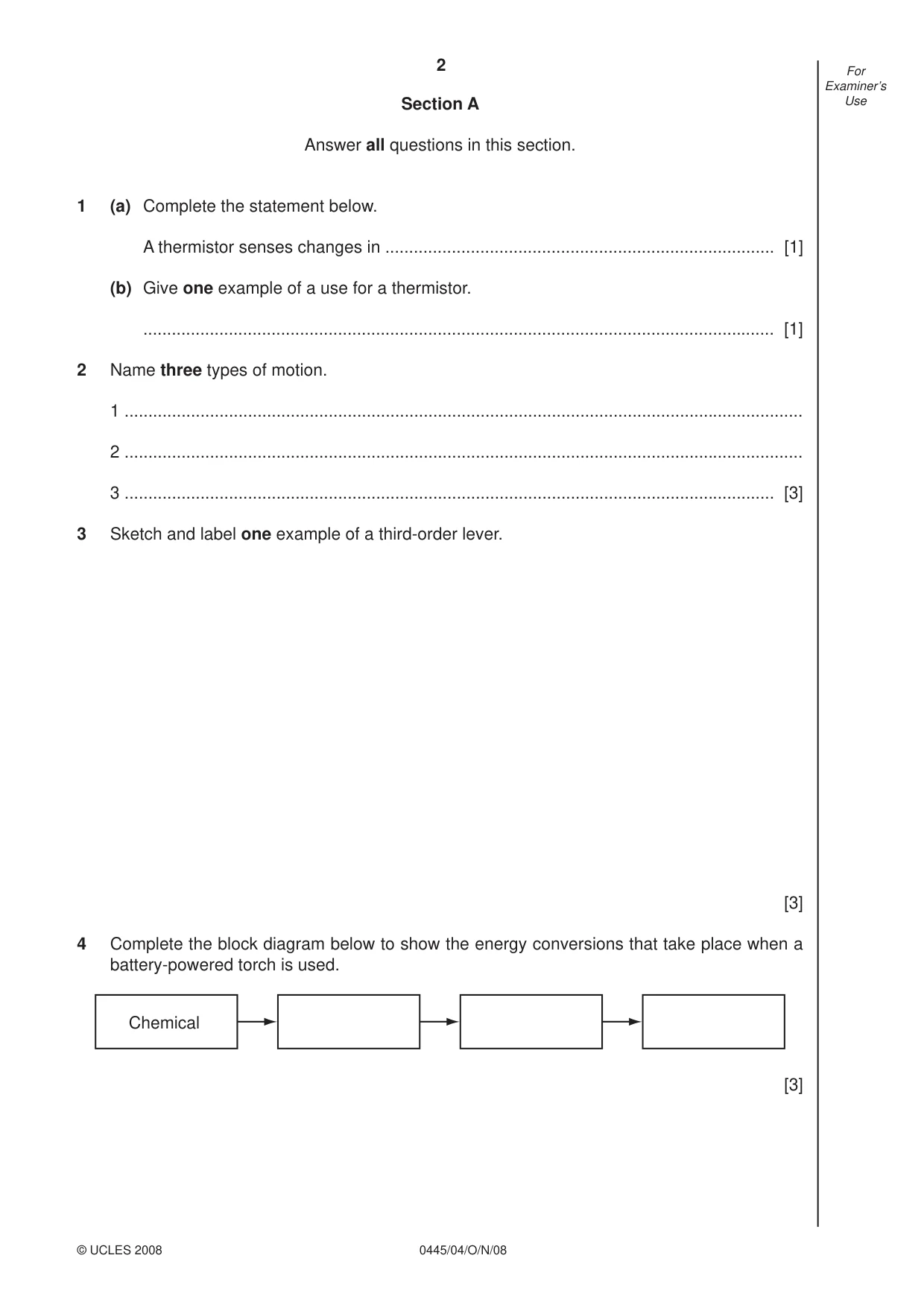
2 0445/04/O/N/08 © UCLES 2008 For Examiner’s Use Section A Answer all questions in this section. 1 (a) Complete the statement below. A thermistor senses changes in … [1] (b) Give one example of a use for a thermistor. … [1] 2 Name three types of motion. 1 … 2 … 3 … [3] 3 Sketch and label one example of a third-order lever. [3] 4 Complete the block diagram below to show the energy conversions that take place when a battery-powered torch is used. Chemical [3]
Question paper, page 3
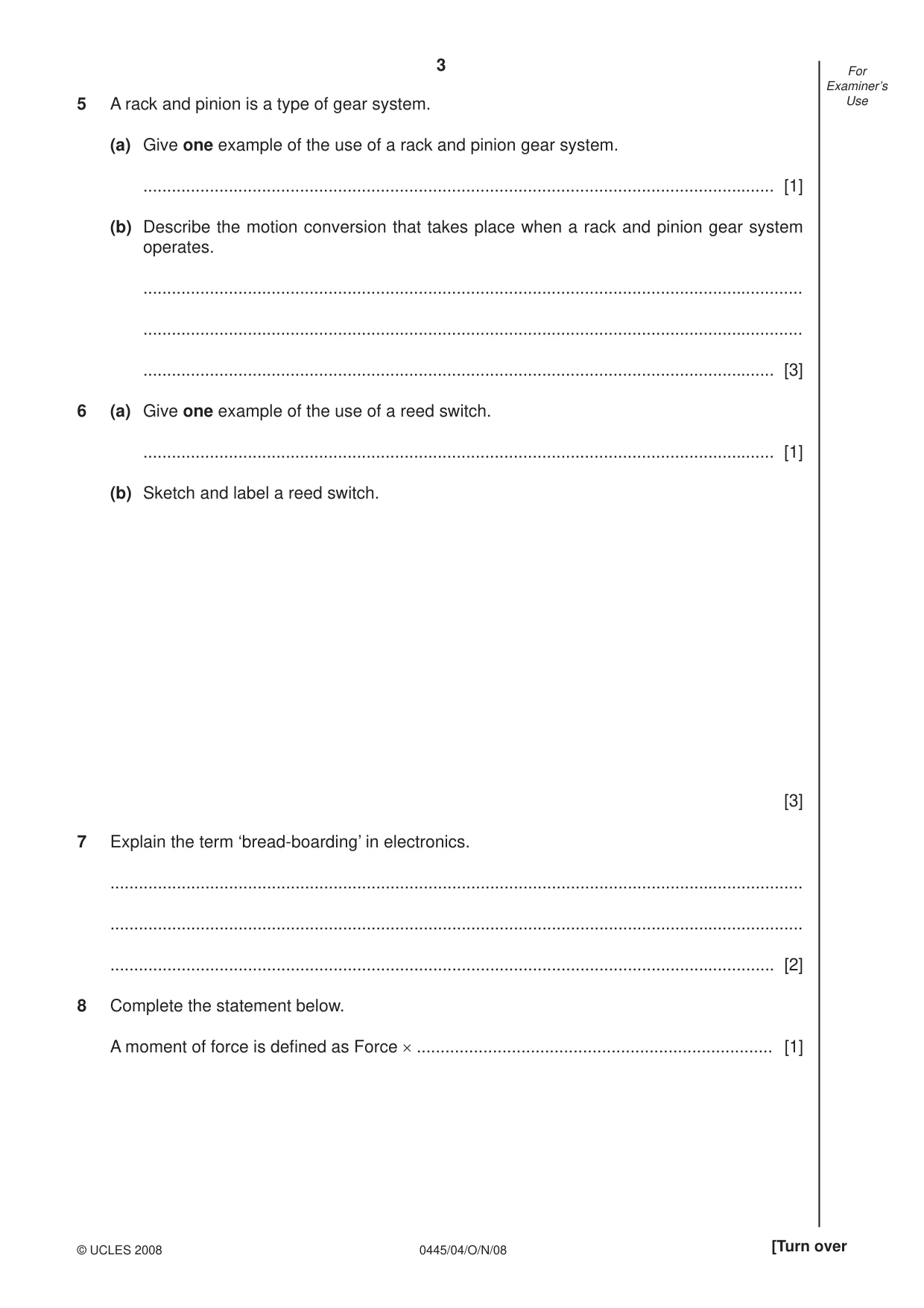
3 0445/04/O/N/08 © UCLES 2008 [Turn over For Examiner’s Use 5 A rack and pinion is a type of gear system. (a) Give one example of the use of a rack and pinion gear system. … [1] (b) Describe the motion conversion that takes place when a rack and pinion gear system operates. … … … [3] 6 (a) Give one example of the use of a reed switch. … [1] (b) Sketch and label a reed switch. [3] 7 Explain the term ‘bread-boarding’ in electronics. … … … [2] 8 Complete the statement below. A moment of force is defi ned as Force × … [1]
Question paper, page 4
4 0445/04/O/N/08 © UCLES 2008 For Examiner’s Use 9 (a) Name the type of force that twists a member. … [1] (b) Give one example of where a twisting force can be found. … [1] 10 Complete the statement below. Flat, toothed, round and vee are all types of … [1]
Question paper, page 5
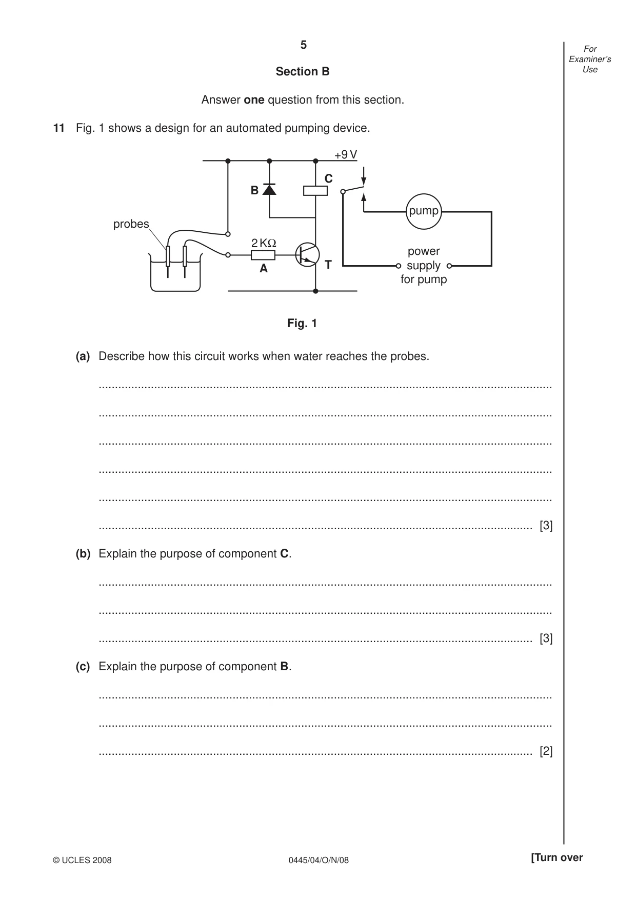
5 0445/04/O/N/08 © UCLES 2008 [Turn over For Examiner’s Use Section B Answer one question from this section. 11 Fig. 1 shows a design for an automated pumping device. 2 KΩ A B C +9 V T power supply for pump pump Fig. 1 probes (a) Describe how this circuit works when water reaches the probes. … … … … … … [3] (b) Explain the purpose of component C. … … … [3] (c) Explain the purpose of component B. … … … [2]
Question paper, page 6
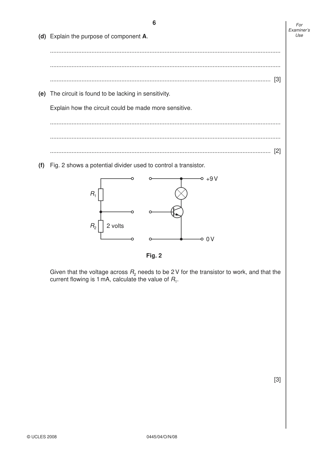
6 0445/04/O/N/08 © UCLES 2008 For Examiner’s Use (d) Explain the purpose of component A. … … … [3] (e) The circuit is found to be lacking in sensitivity. Explain how the circuit could be made more sensitive. … … … [2] (f) Fig. 2 shows a potential divider used to control a transistor. R1 R2 2 volts Fig. 2 +9 V 0 V Given that the voltage across R2 needs to be 2 V for the transistor to work, and that the current fl owing is 1 mA, calculate the value of R1. [3]
Question paper, page 7
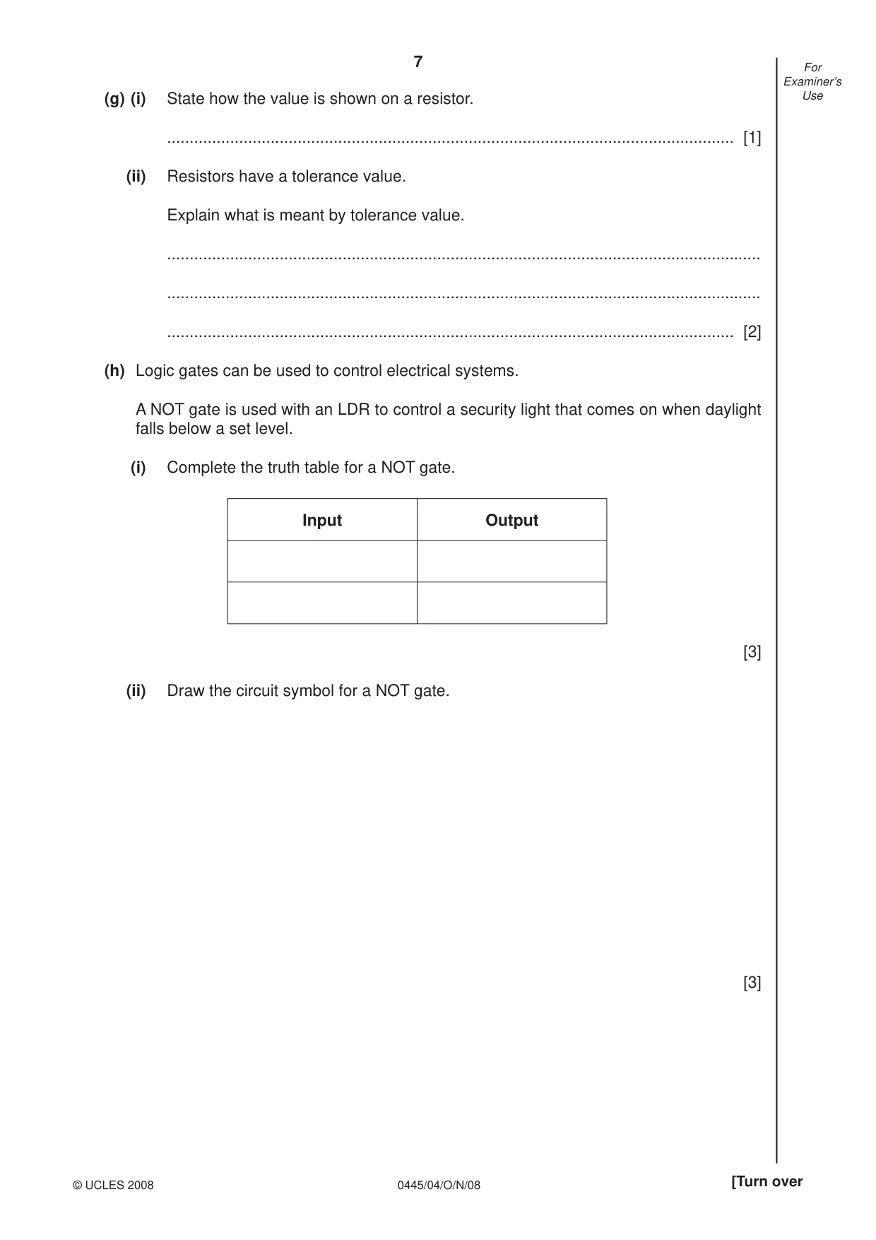
7 0445/04/O/N/08 © UCLES 2008 [Turn over For Examiner’s Use (g) (i) State how the value is shown on a resistor. … [1] (ii) Resistors have a tolerance value. Explain what is meant by tolerance value. … … … [2] (h) Logic gates can be used to control electrical systems. A NOT gate is used with an LDR to control a security light that comes on when daylight falls below a set level. (i) Complete the truth table for a NOT gate. Input Output [3] (ii) Draw the circuit symbol for a NOT gate. [3]
Question paper, page 8
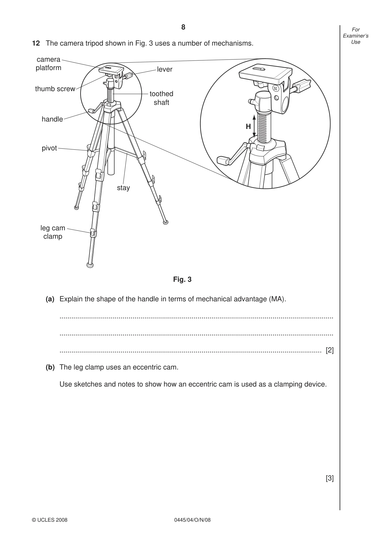
8 0445/04/O/N/08 © UCLES 2008 For Examiner’s Use 12 The camera tripod shown in Fig. 3 uses a number of mechanisms. lever camera platform thumb screw handle pivot stay leg cam clamp toothed shaft H Fig. 3 (a) Explain the shape of the handle in terms of mechanical advantage (MA). … … … [2] (b) The leg clamp uses an eccentric cam. Use sketches and notes to show how an eccentric cam is used as a clamping device. [3]
Question paper, page 9
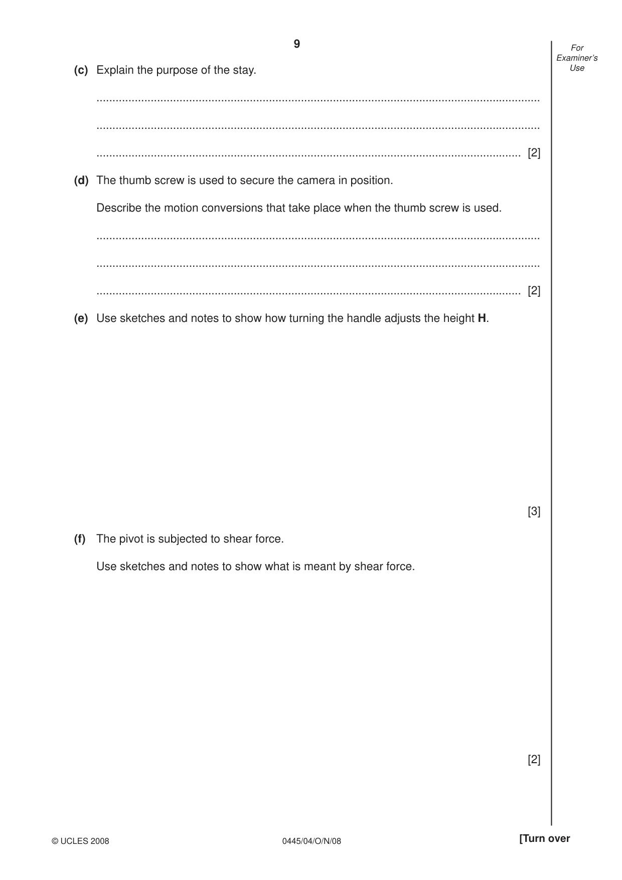
9 0445/04/O/N/08 © UCLES 2008 [Turn over For Examiner’s Use (c) Explain the purpose of the stay. … … … [2] (d) The thumb screw is used to secure the camera in position. Describe the motion conversions that take place when the thumb screw is used. … … … [2] (e) Use sketches and notes to show how turning the handle adjusts the height H. [3] (f) The pivot is subjected to shear force. Use sketches and notes to show what is meant by shear force. [2]
Question paper, page 10
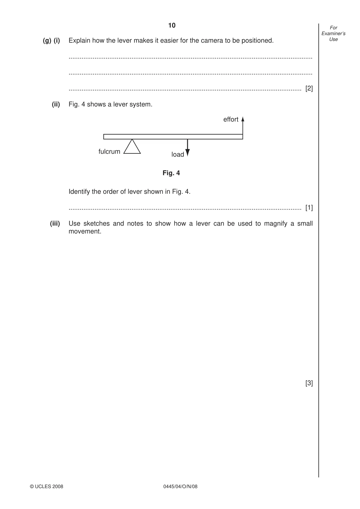
10 0445/04/O/N/08 © UCLES 2008 For Examiner’s Use (g) (i) Explain how the lever makes it easier for the camera to be positioned. … … … [2] (ii) Fig. 4 shows a lever system. effort load fulcrum Fig. 4 Identify the order of lever shown in Fig. 4. … [1] (iii) Use sketches and notes to show how a lever can be used to magnify a small movement. [3]
Question paper, page 11
11 0445/04/O/N/08 © UCLES 2008 [Turn over For Examiner’s Use (h) (i) Describe one example of a construction kit used in the modelling of a mechanical system. … … … [2] (ii) Give one other way of modelling a mechanical system. … [1] (iii) Explain the purpose of modelling a mechanical system prior to making it from resistant materials. … … … [2]
Question paper, page 12
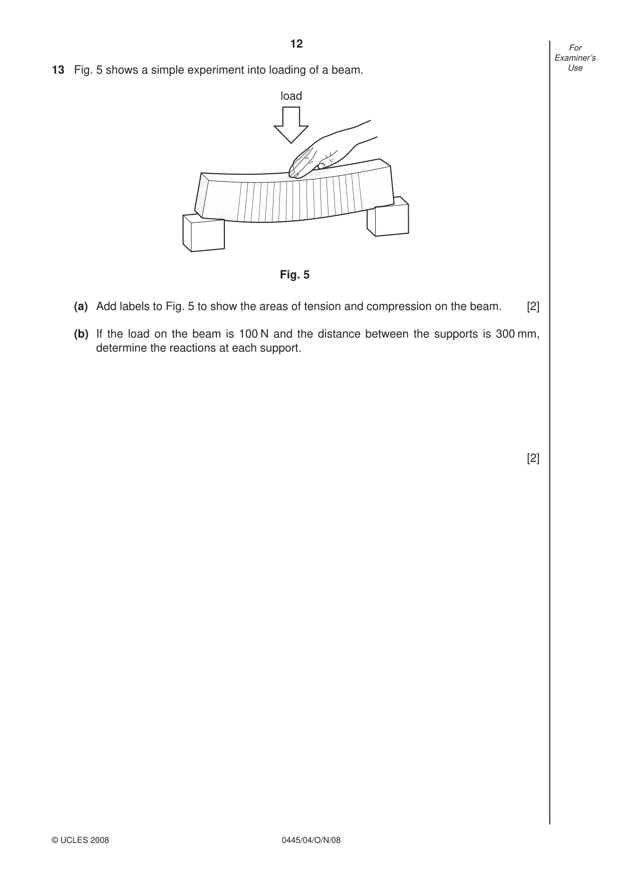
12 0445/04/O/N/08 © UCLES 2008 For Examiner’s Use 13 Fig. 5 shows a simple experiment into loading of a beam. Fig. 5 load (a) Add labels to Fig. 5 to show the areas of tension and compression on the beam. [2] (b) If the load on the beam is 100 N and the distance between the supports is 300 mm, determine the reactions at each support. [2]
Question paper, page 13
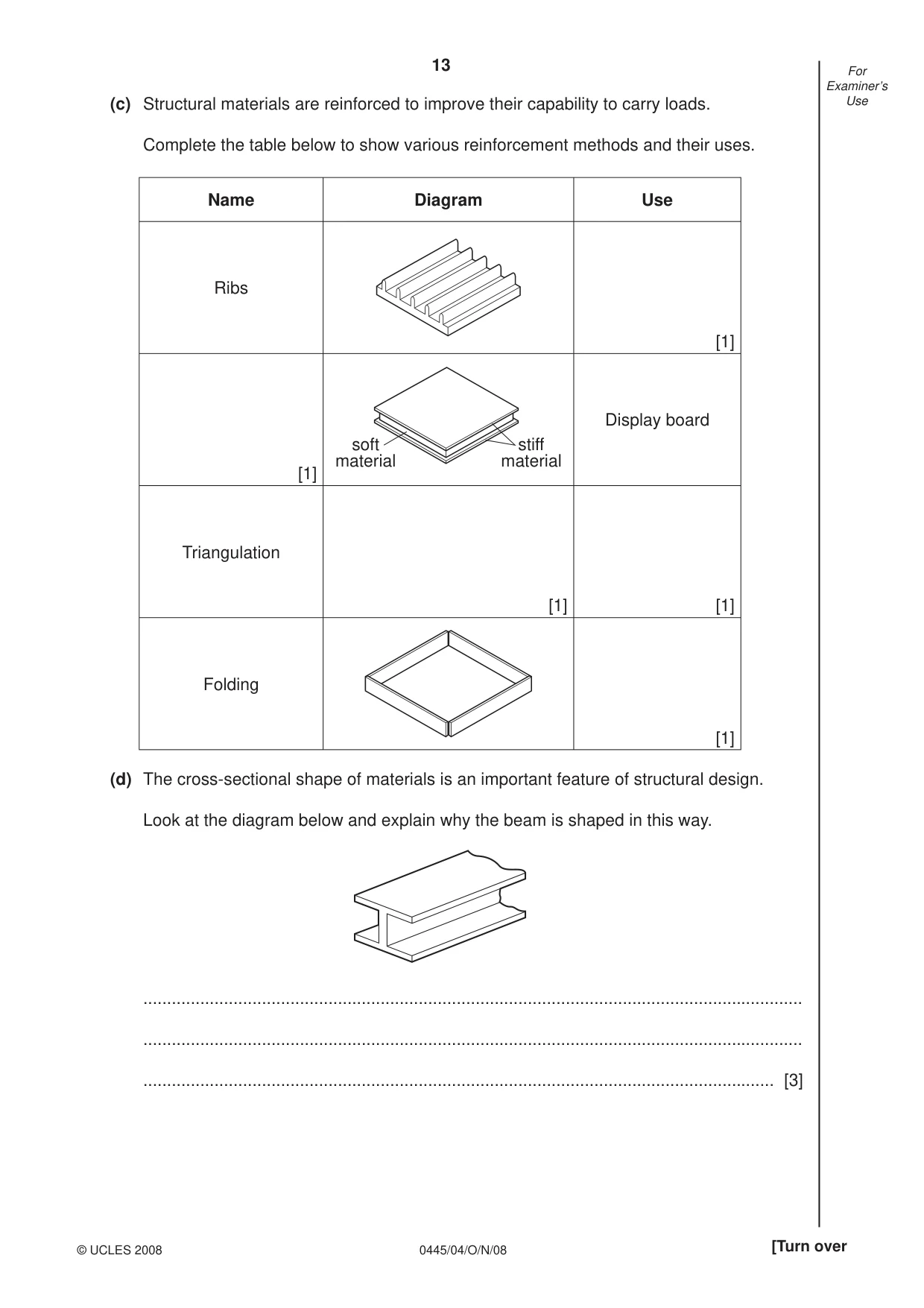
13 0445/04/O/N/08 © UCLES 2008 [Turn over For Examiner’s Use (c) Structural materials are reinforced to improve their capability to carry loads. Complete the table below to show various reinforcement methods and their uses. Name Diagram Use Ribs [1] [1] soft material stiff material Display board Triangulation [1] [1] Folding [1] (d) The cross-sectional shape of materials is an important feature of structural design. Look at the diagram below and explain why the beam is shaped in this way. … … … [3]
Question paper, page 14
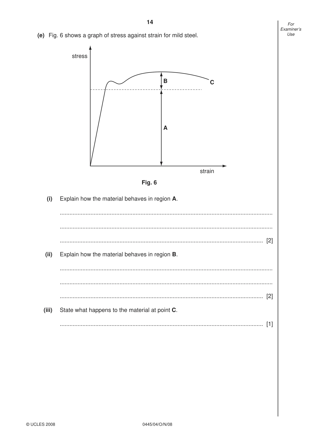
14 0445/04/O/N/08 © UCLES 2008 For Examiner’s Use (e) Fig. 6 shows a graph of stress against strain for mild steel. stress strain A B C Fig. 6 (i) Explain how the material behaves in region A. … … … [2] (ii) Explain how the material behaves in region B. … … … [2] (iii) State what happens to the material at point C. … [1]
Question paper, page 15
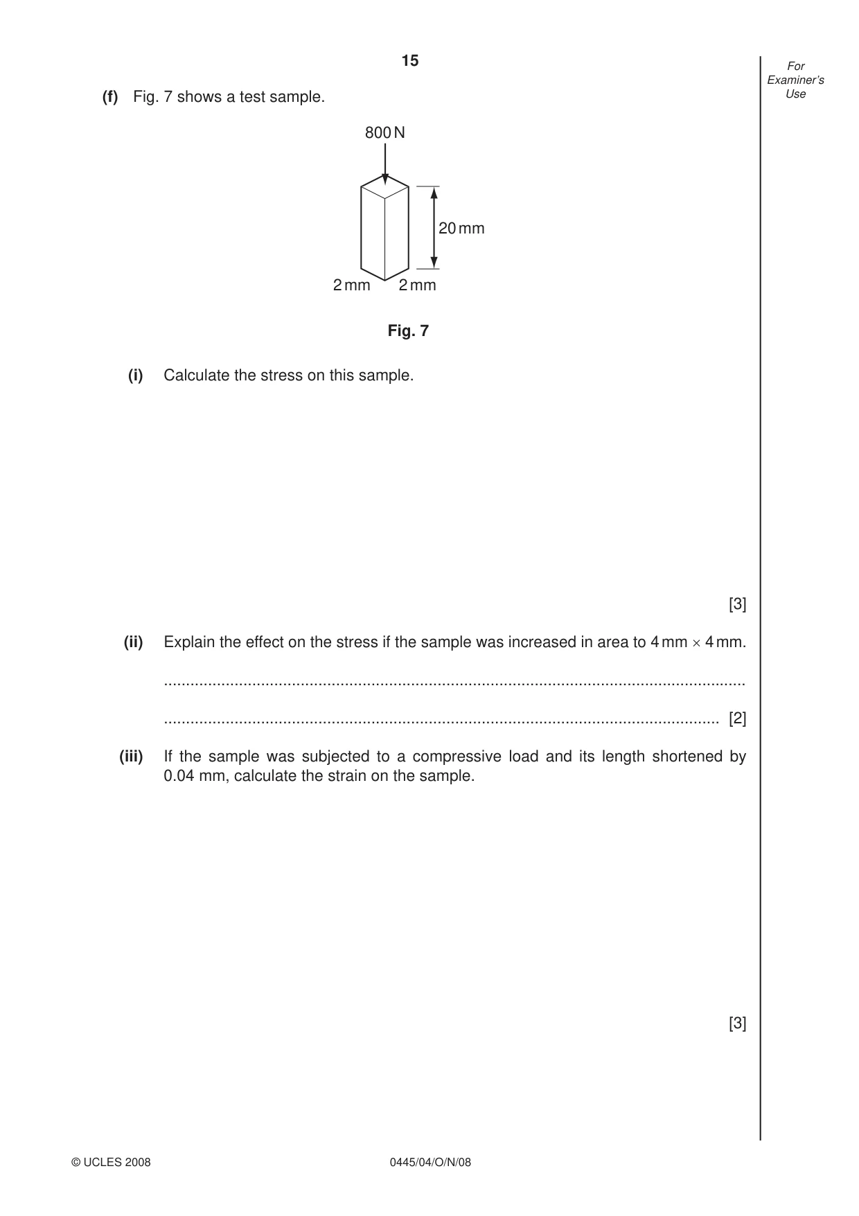
15 0445/04/O/N/08 © UCLES 2008 For Examiner’s Use (f) Fig. 7 shows a test sample. 20 mm 2 mm 2 mm 800 N Fig. 7 (i) Calculate the stress on this sample. [3] (ii) Explain the effect on the stress if the sample was increased in area to 4 mm × 4 mm. … … [2] (iii) If the sample was subjected to a compressive load and its length shortened by 0.04 mm, calculate the strain on the sample. [3]
Question paper, page 16
16 0445/04/O/N/08 Permission to reproduce items where third-party owned material protected by copyright is included has been sought and cleared where possible. Every reasonable effort has been made by the publisher (UCLES) to trace copyright holders, but if any items requiring clearance have unwittingly been included the publisher will be pleased to make amends at the earliest possible opportunity. University of Cambridge International Examinations is part of the Cambridge Assessment Group. Cambridge Assessment is the brand name of University of Cambridge Local Examinations Syndicate (UCLES), which is itself a department of the University of Cambridge. BLANK PAGE
Mark scheme, page 1
UNIVERSITY OF CAMBRIDGE INTERNATIONAL EXAMINATIONS International General Certificate of Secondary Education MARK SCHEME for the October/November 2008 question paper 0445 DESIGN AND TECHNOLOGY 0445/04 Paper 4 (Technology), maximum raw mark 50 This mark scheme is published as an aid to teachers and candidates, to indicate the requirements of the examination. It shows the basis on which Examiners were instructed to award marks. It does not indicate the details of the discussions that took place at an Examiners’ meeting before marking began. All Examiners are instructed that alternative correct answers and unexpected approaches in candidates’ scripts must be given marks that fairly reflect the relevant knowledge and skills demonstrated. Mark schemes must be read in conjunction with the question papers and the report on the examination. • CIE will not enter into discussions or correspondence in connection with these mark schemes. CIE is publishing the mark schemes for the October/November 2008 question papers for most IGCSE, GCE Advanced Level and Advanced Subsidiary Level syllabuses and some Ordinary Level syllabuses. www.XtremePapers.com
Mark scheme, page 2
Page 2 Mark Scheme Syllabus Paper IGCSE – October/November 2008 0445 04 © UCLES 2008 Section A 1 (a) Temperature [1] (b) Freezer, microwave, oven, car frost alarm… [1] 2 Linear, rotary, reciprocating, oscillating [3] 3 Load (1); Effort (1); Fulcrum (1) [3] 4 [3] 5 (a) Car steering/pillar drill/ [1] (b) Rotary (1) to Linear (1) change in direction or axis (1) [3] 6 (a) Burglar alarm sensor on window/door [1] (b) [3] (c) Burglar alarm sensor on window/door [1] 7 Modelling a circuit (1) using discrete components in a pegboard (1) [2] 8 Distance [1] 9 (a) Torsion [1] (b) Drive shafts [1] 10 Pulleys/Belts [1] Chemical Electrical (1) Light (1) Heat (1) (1) (1) (1)
Mark scheme, page 3
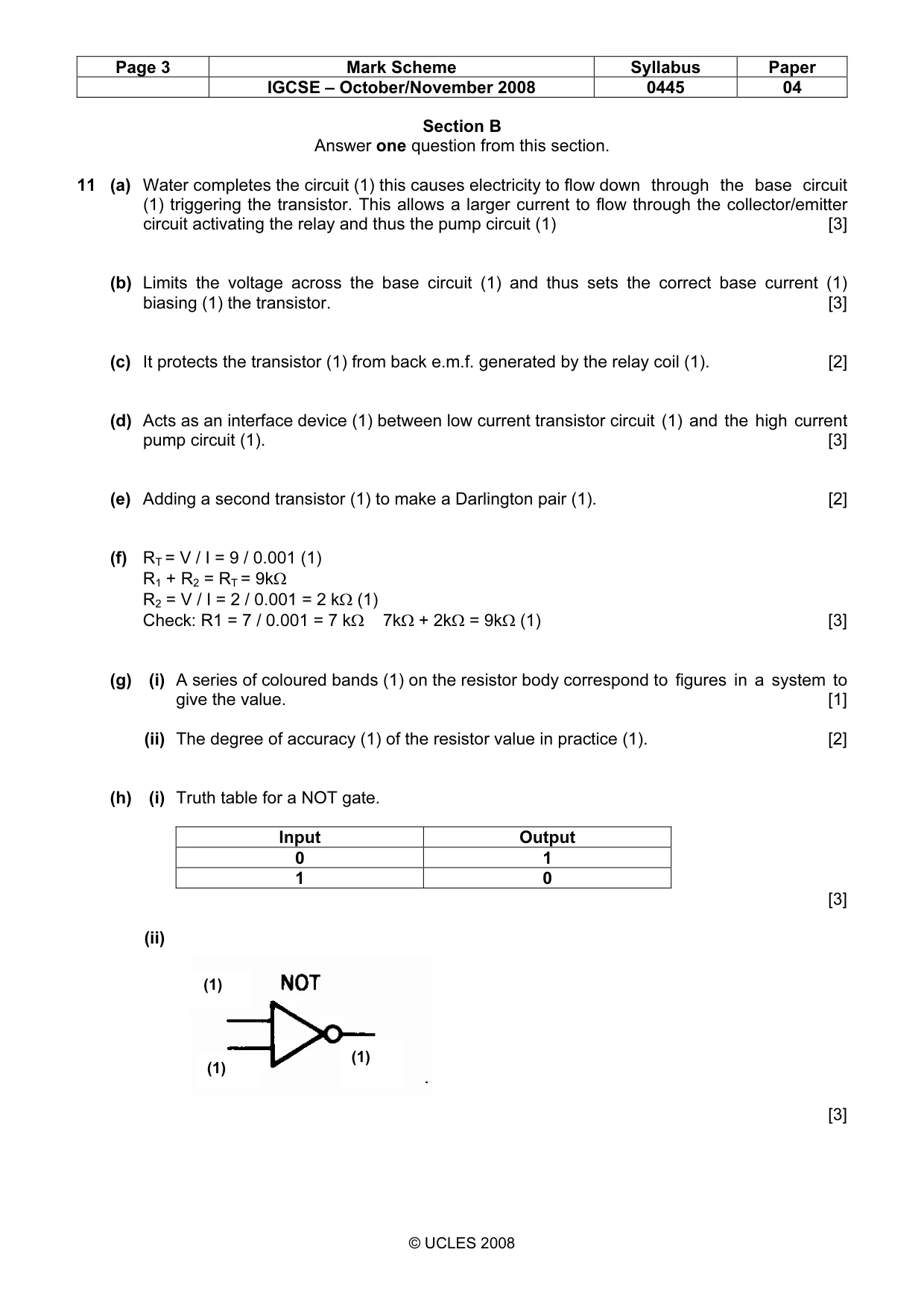
Page 3 Mark Scheme Syllabus Paper IGCSE – October/November 2008 0445 04 © UCLES 2008 Section B Answer one question from this section. 11 (a) Water completes the circuit (1) this causes electricity to flow down through the base circuit (1) triggering the transistor. This allows a larger current to flow through the collector/emitter circuit activating the relay and thus the pump circuit (1) [3] (b) Limits the voltage across the base circuit (1) and thus sets the correct base current (1) biasing (1) the transistor. [3] (c) It protects the transistor (1) from back e.m.f. generated by the relay coil (1). [2] (d) Acts as an interface device (1) between low current transistor circuit (1) and the high current pump circuit (1). [3] (e) Adding a second transistor (1) to make a Darlington pair (1). [2] (f) RT = V / I = 9 / 0.001 (1) R1 + R2 = RT = 9kΩ R2 = V / I = 2 / 0.001 = 2 kΩ (1) Check: R1 = 7 / 0.001 = 7 kΩ 7kΩ + 2kΩ = 9kΩ (1) [3] (g) (i) A series of coloured bands (1) on the resistor body correspond to figures in a system to give the value. [1] (ii) The degree of accuracy (1) of the resistor value in practice (1). [2] (h) (i) Truth table for a NOT gate. Input Output 0 1 1 0 [3] (ii) [3] (1) (1) (1)
Mark scheme, page 4
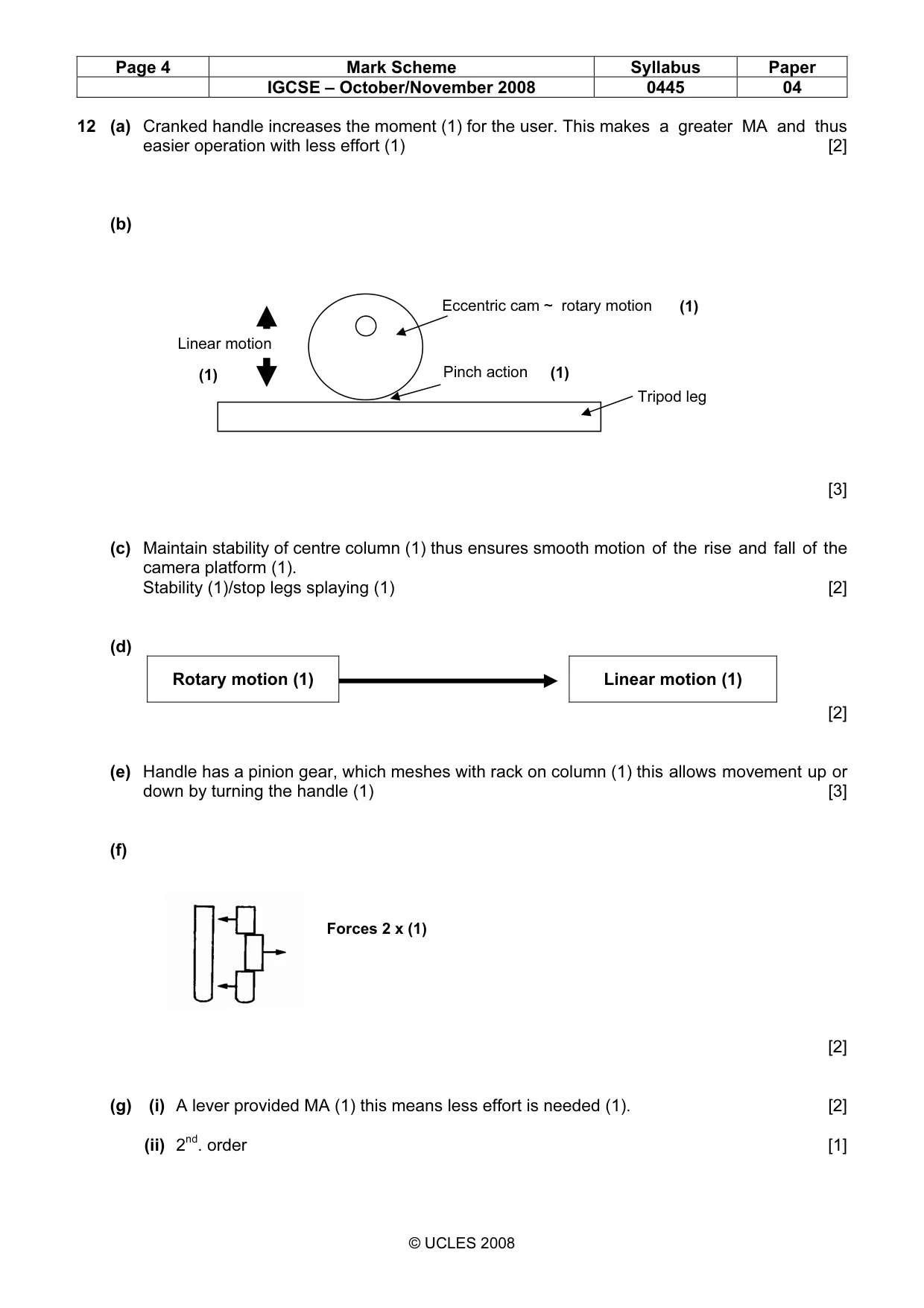
Page 4 Mark Scheme Syllabus Paper IGCSE – October/November 2008 0445 04 © UCLES 2008 12 (a) Cranked handle increases the moment (1) for the user. This makes a greater MA and thus easier operation with less effort (1) [2] (b) [3] (c) Maintain stability of centre column (1) thus ensures smooth motion of the rise and fall of the camera platform (1). Stability (1)/stop legs splaying (1) [2] (d) Rotary motion (1) Linear motion (1) [2] (e) Handle has a pinion gear, which meshes with rack on column (1) this allows movement up or down by turning the handle (1) [3] (f) [2] (g) (i) A lever provided MA (1) this means less effort is needed (1). [2] (ii) 2nd. order [1] Eccentric cam ~ rotary motion Tripod leg Linear motion Pinch action (1) (1) (1) Forces 2 x (1)
Mark scheme, page 5
Page 5 Mark Scheme Syllabus Paper IGCSE – October/November 2008 0445 04 © UCLES 2008 (iii) [3] (h) (i) Using “Meccano” (1) pieces bolted together (1). [2] (ii) CAD/card and paper fasteners [1] (iii) Allows adjustment of sizes, positions of pivots etc. (1) without using expensive materials (1). [2] 13 (a) Compression ~ top of beam (1) Tension ~ bottom of beam (1) [2] (b) As symmetrical RL = RR (1) = 50N (1) [2] (c) Name Diagram Use Ribs Plastics packaging [1] Lamination/Sandwich [1] Display board Triangulation [1] Roof truss [1] Folding Cardboard packaging [1] (1) (1) (1)
Mark scheme, page 6
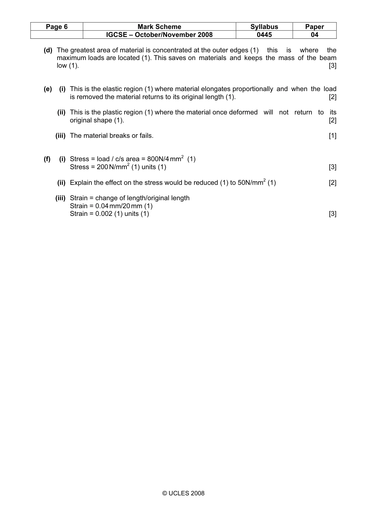
Page 6 Mark Scheme Syllabus Paper IGCSE – October/November 2008 0445 04 © UCLES 2008 (d) The greatest area of material is concentrated at the outer edges (1) this is where the maximum loads are located (1). This saves on materials and keeps the mass of the beam low (1). [3] (e) (i) This is the elastic region (1) where material elongates proportionally and when the load is removed the material returns to its original length (1). [2] (ii) This is the plastic region (1) where the material once deformed will not return to its original shape (1). [2] (iii) The material breaks or fails. [1] (f) (i) Stress = load / c/s area = 800N/4 mm2 (1) Stress = 200 N/mm2 (1) units (1) [3] (ii) Explain the effect on the stress would be reduced (1) to 50N/mm2 (1) [2] (iii) Strain = change of length/original length Strain = 0.04 mm/20 mm (1) Strain = 0.002 (1) units (1) [3]
What you needed in this session
Cambridge’s own grade thresholds for 2008 Oct/Nov, Paper 4 · Variant 1. A higher threshold means an easier paper — the bar moves with how the cohort did.