Cambridge IGCSE Design and Technology 0445 — 2007 Oct/Nov Paper 4 · Variant 1
0445/41/O/N/07 · 50 marks · ≈56 min
The question paper and its mark scheme, free to read here and free to download. This is Cambridge’s own paper, exactly as it was sat.
Question paper16 pages


Mark scheme6 pages
Answers below. Sit the paper first if you are practising.
Paper as text
Question paper, page 1
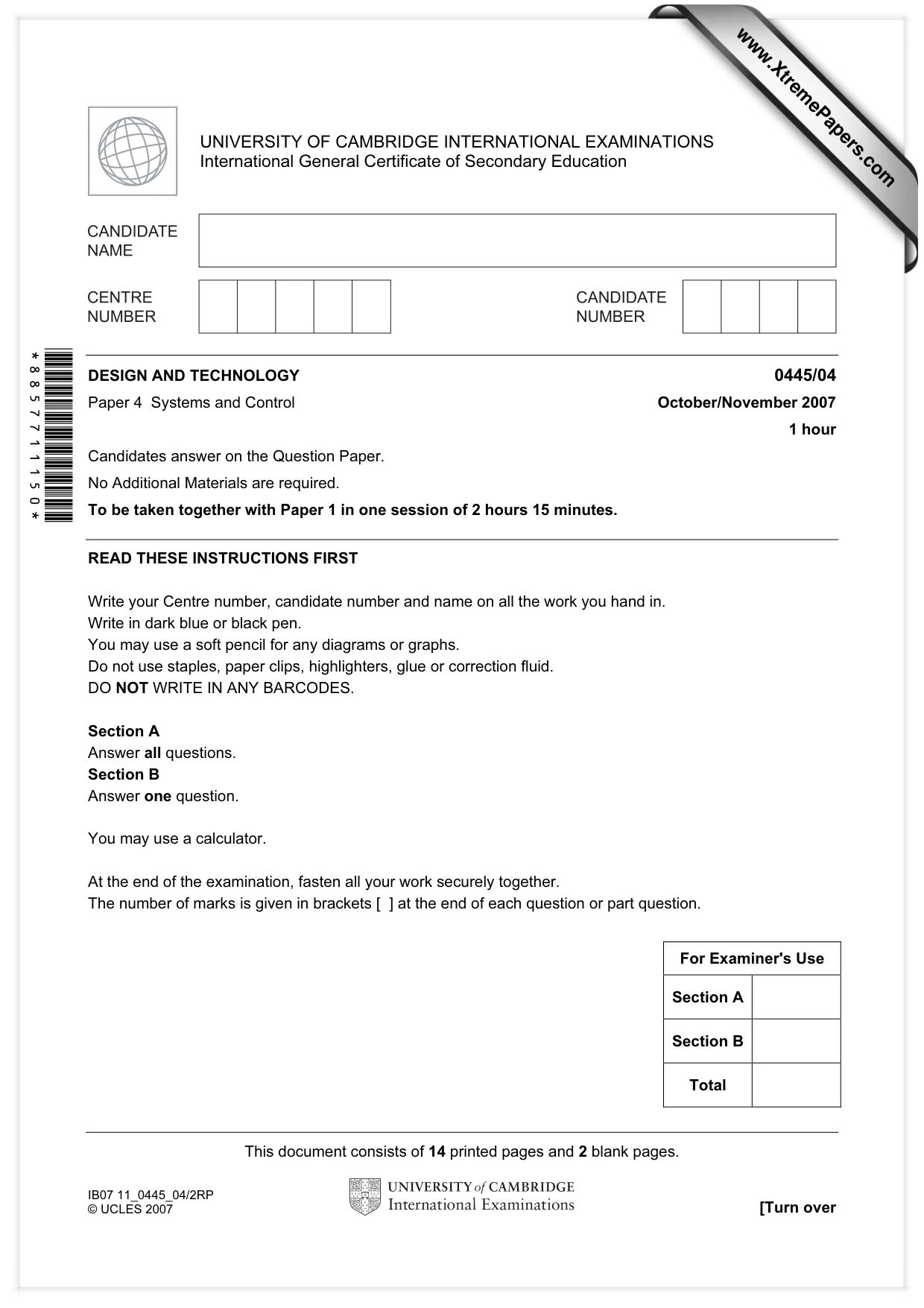
This document consists of 14 printed pages and 2 blank pages. IB07 11_0445_04/2RP © UCLES 2007 [Turn over *8857711150* For Examiner's Use Section A Section B Total UNIVERSITY OF CAMBRIDGE INTERNATIONAL EXAMINATIONS International General Certificate of Secondary Education DESIGN AND TECHNOLOGY 0445/04 Paper 4 Systems and Control October/November 2007 1 hour Candidates answer on the Question Paper. No Additional Materials are required. To be taken together with Paper 1 in one session of 2 hours 15 minutes. READ THESE INSTRUCTIONS FIRST Write your Centre number, candidate number and name on all the work you hand in. Write in dark blue or black pen. You may use a soft pencil for any diagrams or graphs. Do not use staples, paper clips, highlighters, glue or correction fluid. DO NOT WRITE IN ANY BARCODES. Section A Answer all questions. Section B Answer one question. You may use a calculator. At the end of the examination, fasten all your work securely together. The number of marks is given in brackets [ ] at the end of each question or part question. www.XtremePapers.com
Question paper, page 2
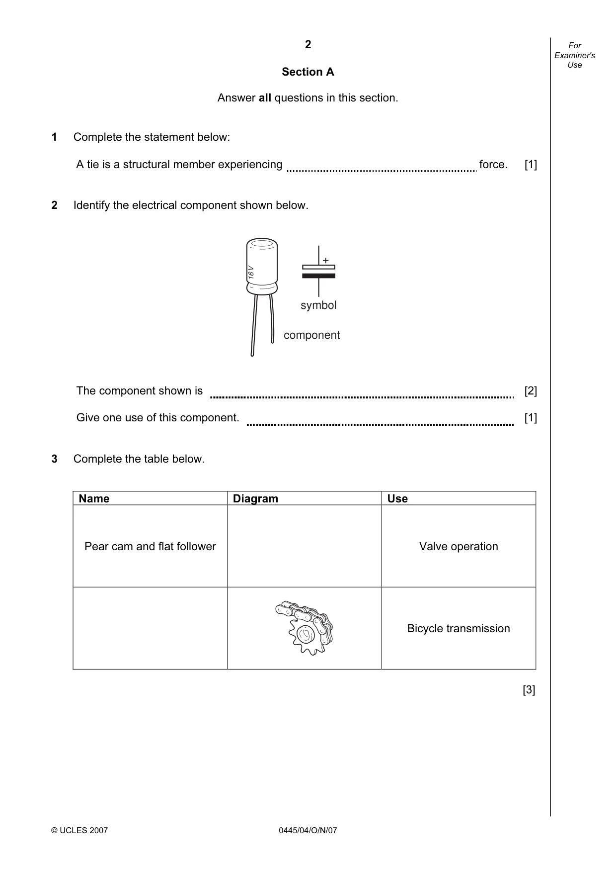
2 © UCLES 2007 0445/04/O/N/07 For Examiner's Use Section A Answer all questions in this section. 1 Complete the statement below: A tie is a structural member experiencing force. [1] 2 Identify the electrical component shown below. 16 V + symbol component The component shown is [2] Give one use of this component. [1] 3 Complete the table below. Name Diagram Use Pear cam and flat follower Valve operation Bicycle transmission [3]
Question paper, page 3
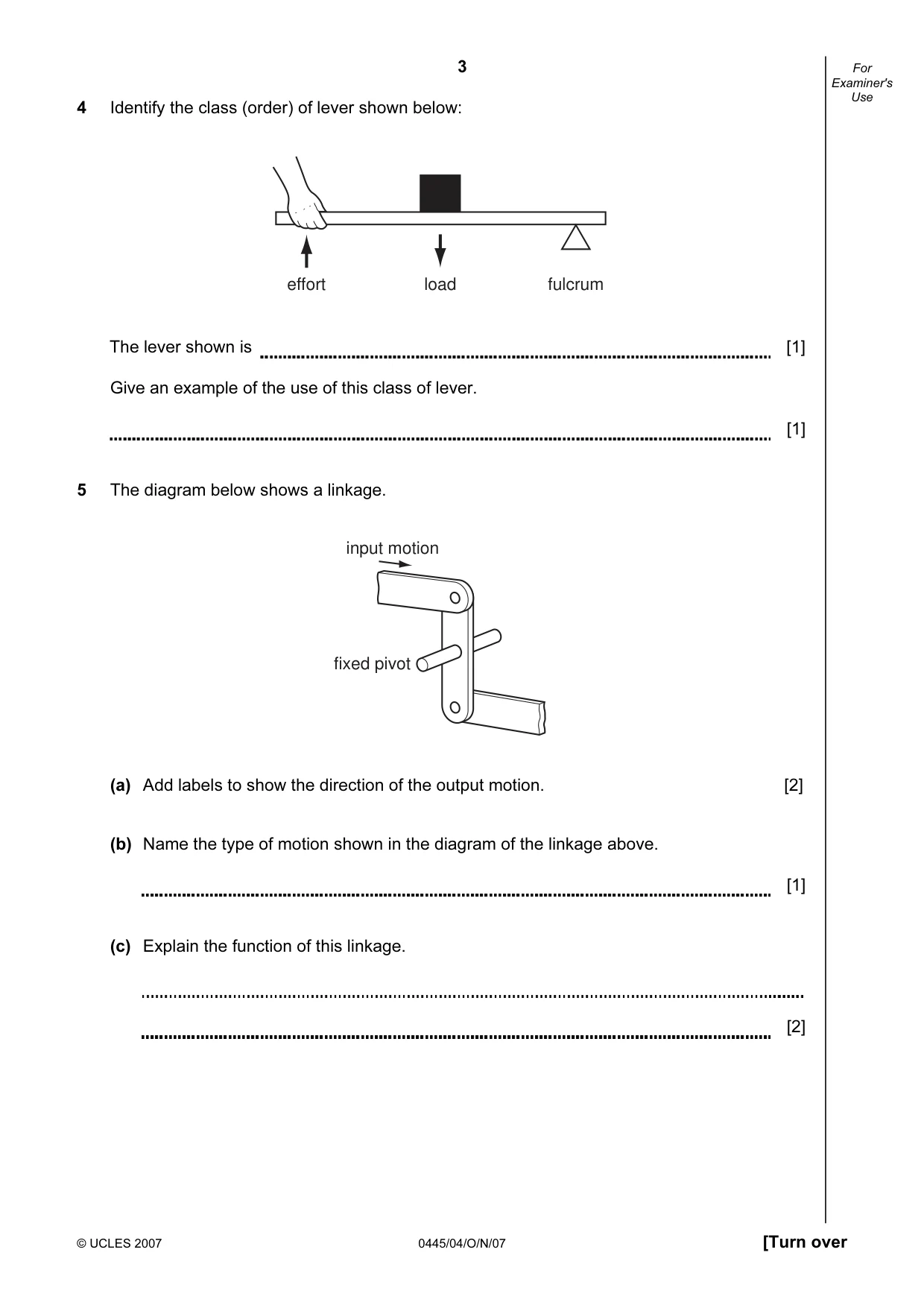
3 © UCLES 2007 0445/04/O/N/07 [Turn over For Examiner's Use 4 Identify the class (order) of lever shown below: load effort fulcrum The lever shown is [1] Give an example of the use of this class of lever. [1] 5 The diagram below shows a linkage. input motion fixed pivot (a) Add labels to show the direction of the output motion. [2] (b) Name the type of motion shown in the diagram of the linkage above. [1] (c) Explain the function of this linkage. [2]
Question paper, page 4
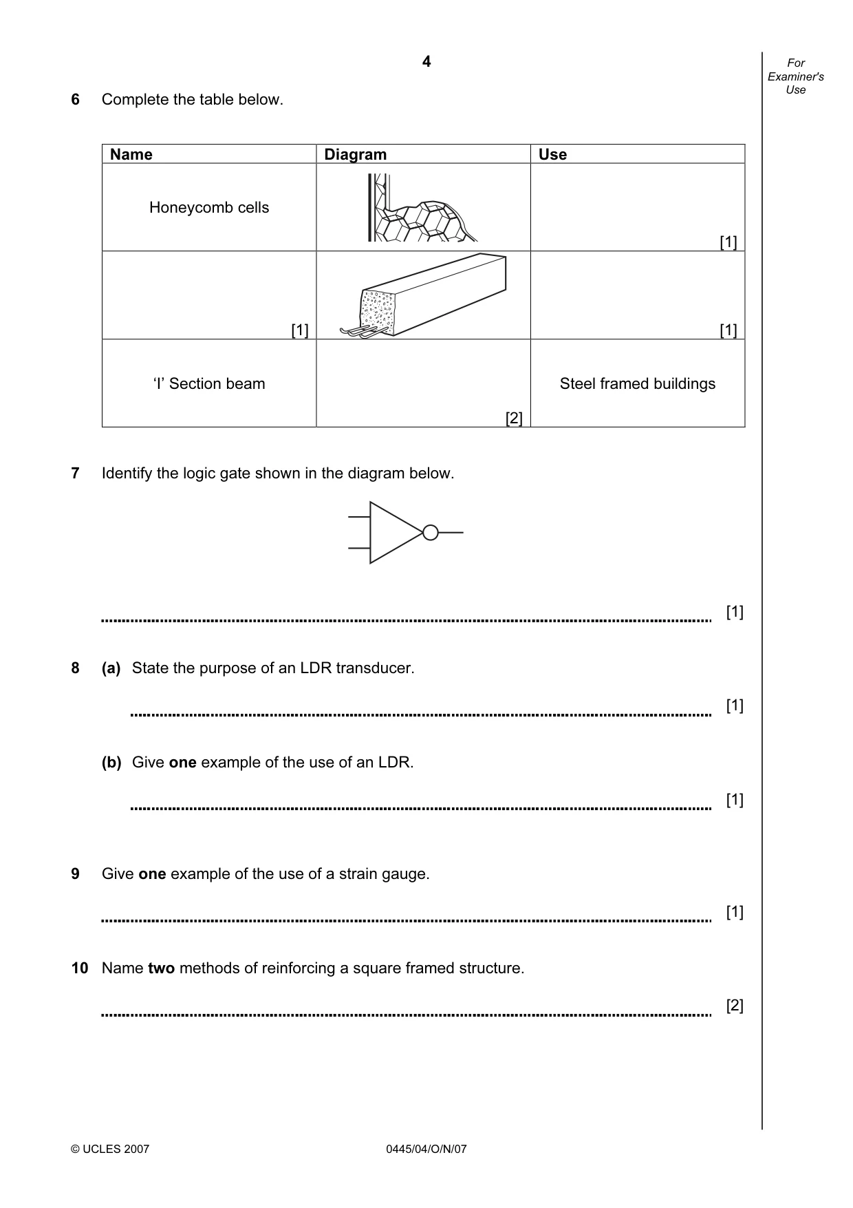
4 © UCLES 2007 0445/04/O/N/07 For Examiner's Use 6 Complete the table below. Name Diagram Use Honeycomb cells [1] [1] [1] ‘I’ Section beam [2] Steel framed buildings 7 Identify the logic gate shown in the diagram below. [1] 8 (a) State the purpose of an LDR transducer. [1] (b) Give one example of the use of an LDR. [1] 9 Give one example of the use of a strain gauge. [1] 10 Name two methods of reinforcing a square framed structure. [2]
Question paper, page 5
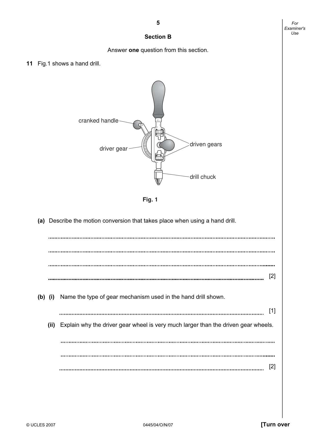
5 © UCLES 2007 0445/04/O/N/07 [Turn over For Examiner's Use Section B Answer one question from this section. 11 Fig.1 shows a hand drill. cranked handle driver gear driven gears drill chuck Fig. 1 (a) Describe the motion conversion that takes place when using a hand drill. [2] (b) (i) Name the type of gear mechanism used in the hand drill shown. [1] (ii) Explain why the driver gear wheel is very much larger than the driven gear wheels. [2]
Question paper, page 6
6 © UCLES 2007 0445/04/O/N/07 For Examiner's Use (iii) Give one reason for the top driven gear wheel nearest the handle. [2] (c) Explain why the handle is cranked. [3] (d) The driver wheel has 60 teeth and the driven wheels have 12 teeth each. (i) Calculate the gear ratio for this mechanism. [3] (ii) If the driver wheel is turned at 60 rpm, calculate the speed of the drill chuck. [3]
Question paper, page 7
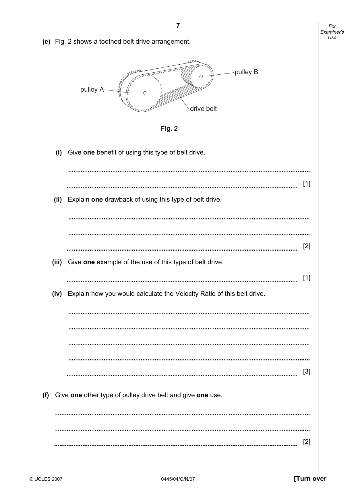
7 © UCLES 2007 0445/04/O/N/07 [Turn over For Examiner's Use (e) Fig. 2 shows a toothed belt drive arrangement. pulley A pulley B drive belt Fig. 2 (i) Give one benefit of using this type of belt drive. [1] (ii) Explain one drawback of using this type of belt drive. [2] (iii) Give one example of the use of this type of belt drive. [1] (iv) Explain how you would calculate the Velocity Ratio of this belt drive. [3] (f) Give one other type of pulley drive belt and give one use. [2]
Question paper, page 8
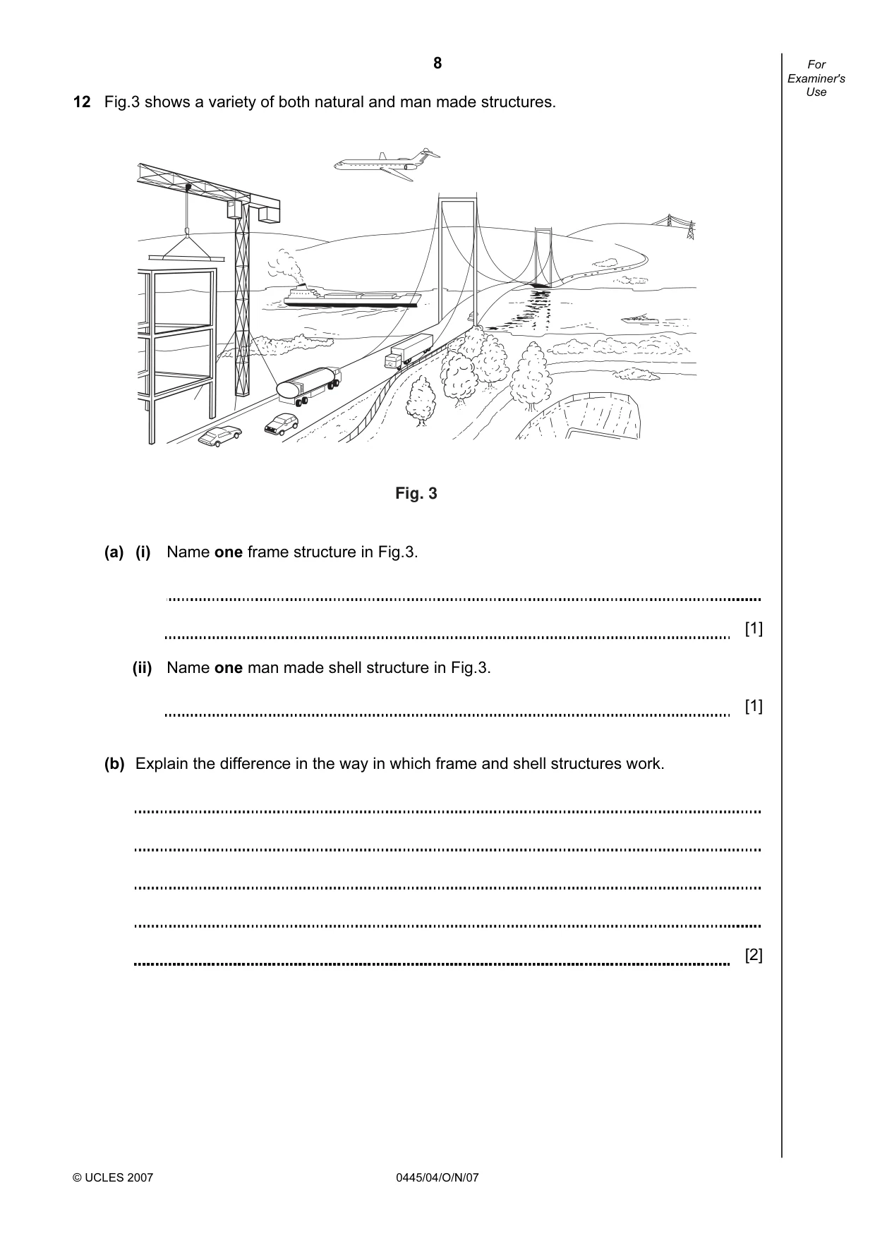
8 © UCLES 2007 0445/04/O/N/07 For Examiner's Use 12 Fig.3 shows a variety of both natural and man made structures. Fig. 3 (a) (i) Name one frame structure in Fig.3. [1] (ii) Name one man made shell structure in Fig.3. [1] (b) Explain the difference in the way in which frame and shell structures work. [2]
Question paper, page 9
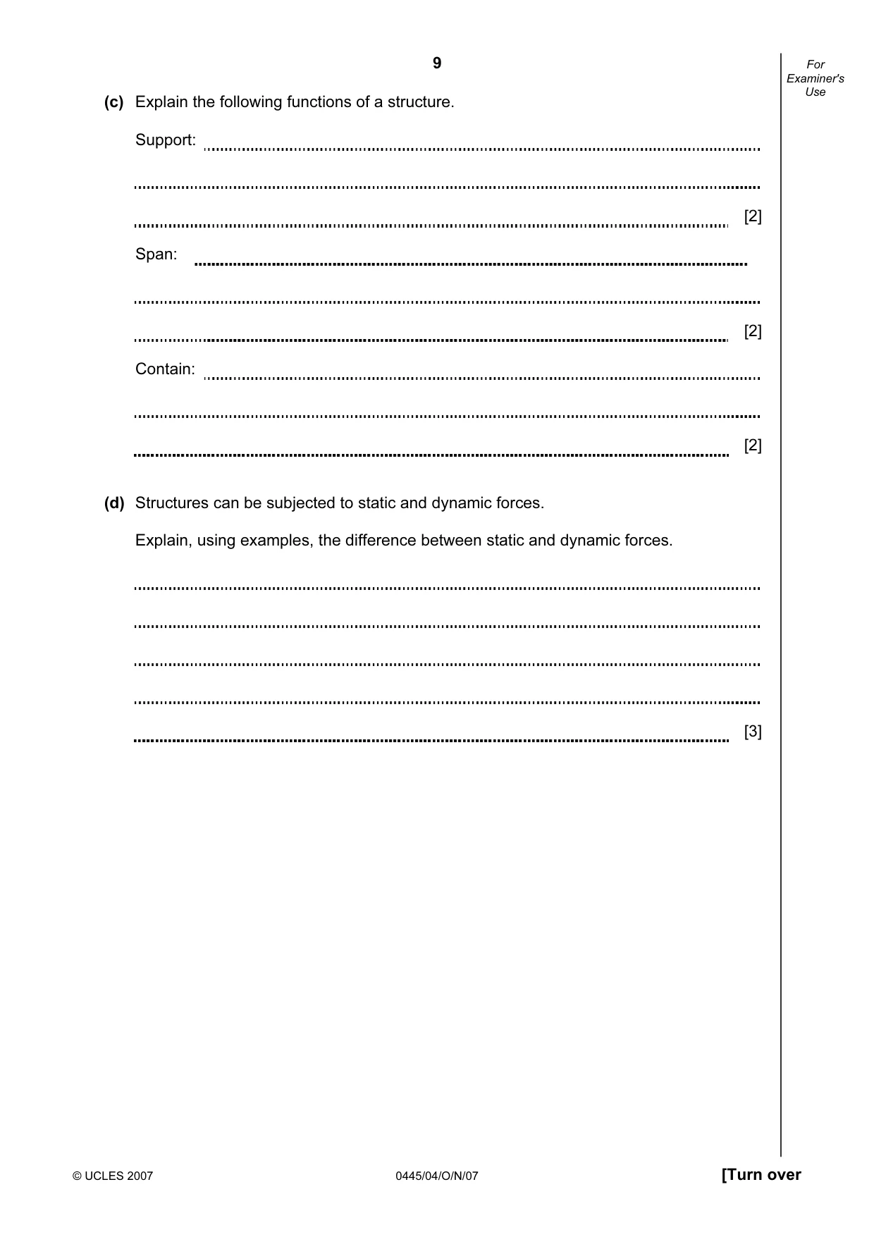
9 © UCLES 2007 0445/04/O/N/07 [Turn over For Examiner's Use (c) Explain the following functions of a structure. Support: [2] Span: [2] Contain: [2] (d) Structures can be subjected to static and dynamic forces. Explain, using examples, the difference between static and dynamic forces. [3]
Question paper, page 10
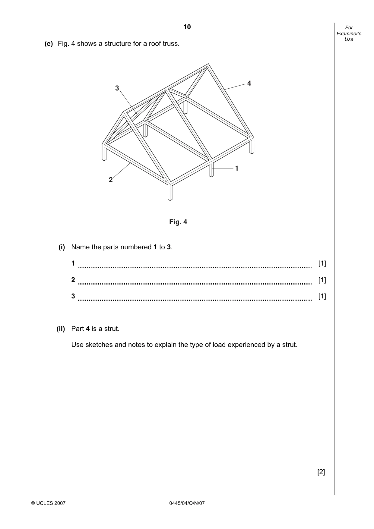
10 © UCLES 2007 0445/04/O/N/07 For Examiner's Use (e) Fig. 4 shows a structure for a roof truss. Fig. 4 3 2 1 4 (i) Name the parts numbered 1 to 3. 1 [1] 2 [1] 3 [1] (ii) Part 4 is a strut. Use sketches and notes to explain the type of load experienced by a strut. [2]
Question paper, page 11
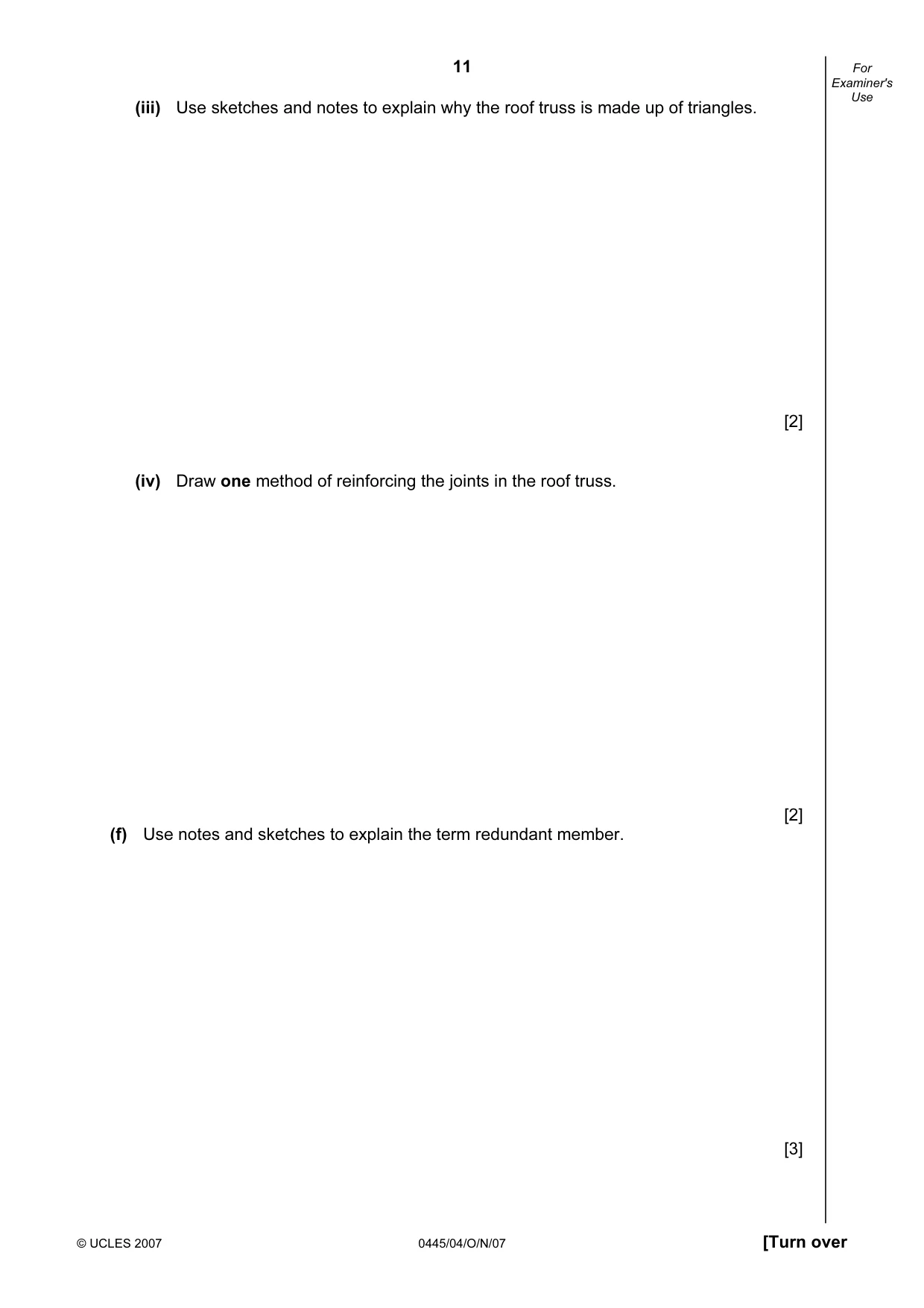
11 © UCLES 2007 0445/04/O/N/07 [Turn over For Examiner's Use (iii) Use sketches and notes to explain why the roof truss is made up of triangles. [2] (iv) Draw one method of reinforcing the joints in the roof truss. [2] (f) Use notes and sketches to explain the term redundant member. [3]
Question paper, page 12
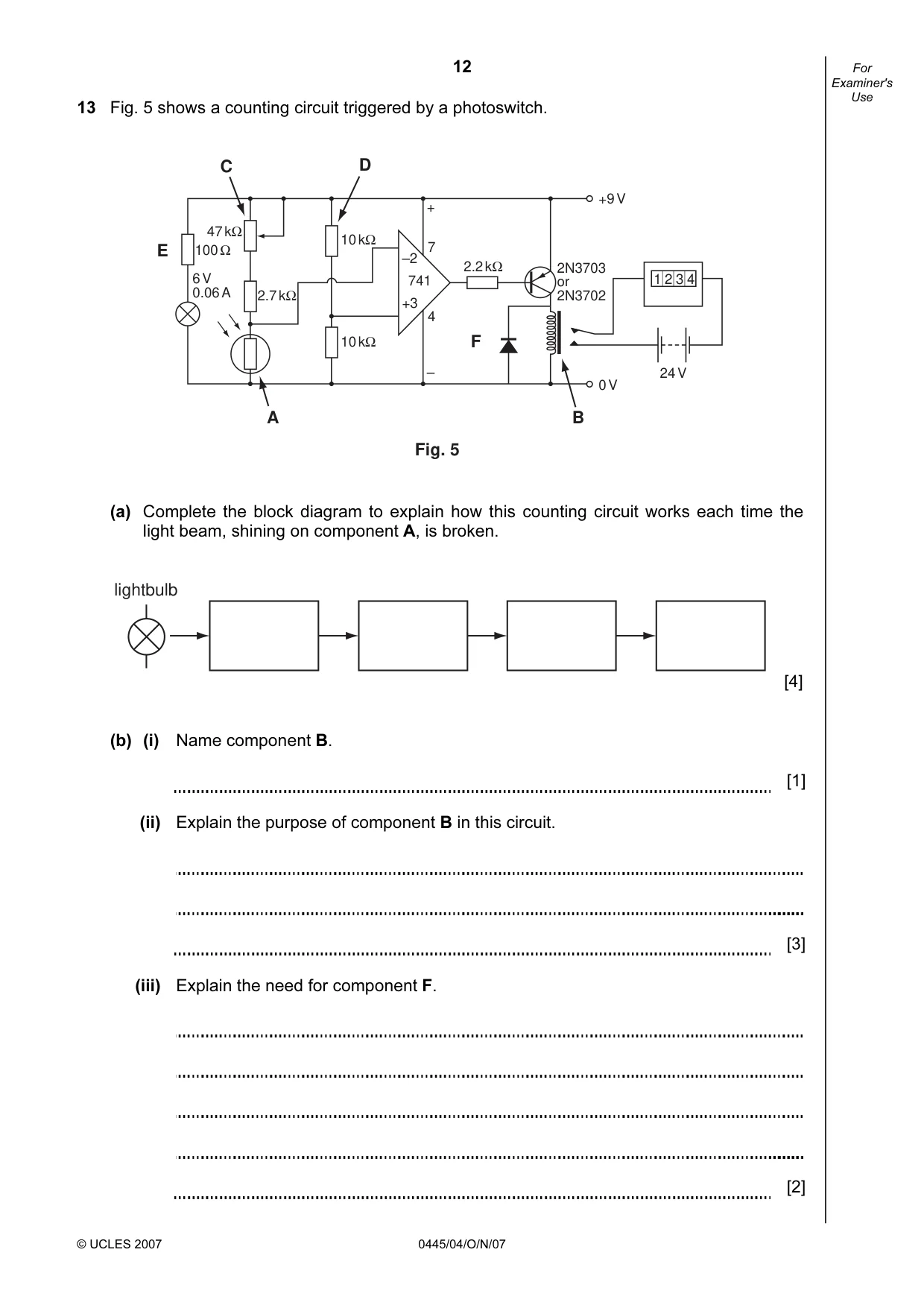
12 © UCLES 2007 0445/04/O/N/07 For Examiner's Use 13 Fig. 5 shows a counting circuit triggered by a photoswitch. 100 Ω 47 kΩ 10 kΩ 10 kΩ 2.7 kΩ 2.2 kΩ 6 V 0.06 A –2 +3 741 7 4 + – 24 V +9 V 0 V 2N3703 or 2N3702 1 2 3 4 B F A E C D Fig. 5 (a) Complete the block diagram to explain how this counting circuit works each time the light beam, shining on component A, is broken. lightbulb [4] (b) (i) Name component B. [1] (ii) Explain the purpose of component B in this circuit. [3] (iii) Explain the need for component F. [2]
Question paper, page 13
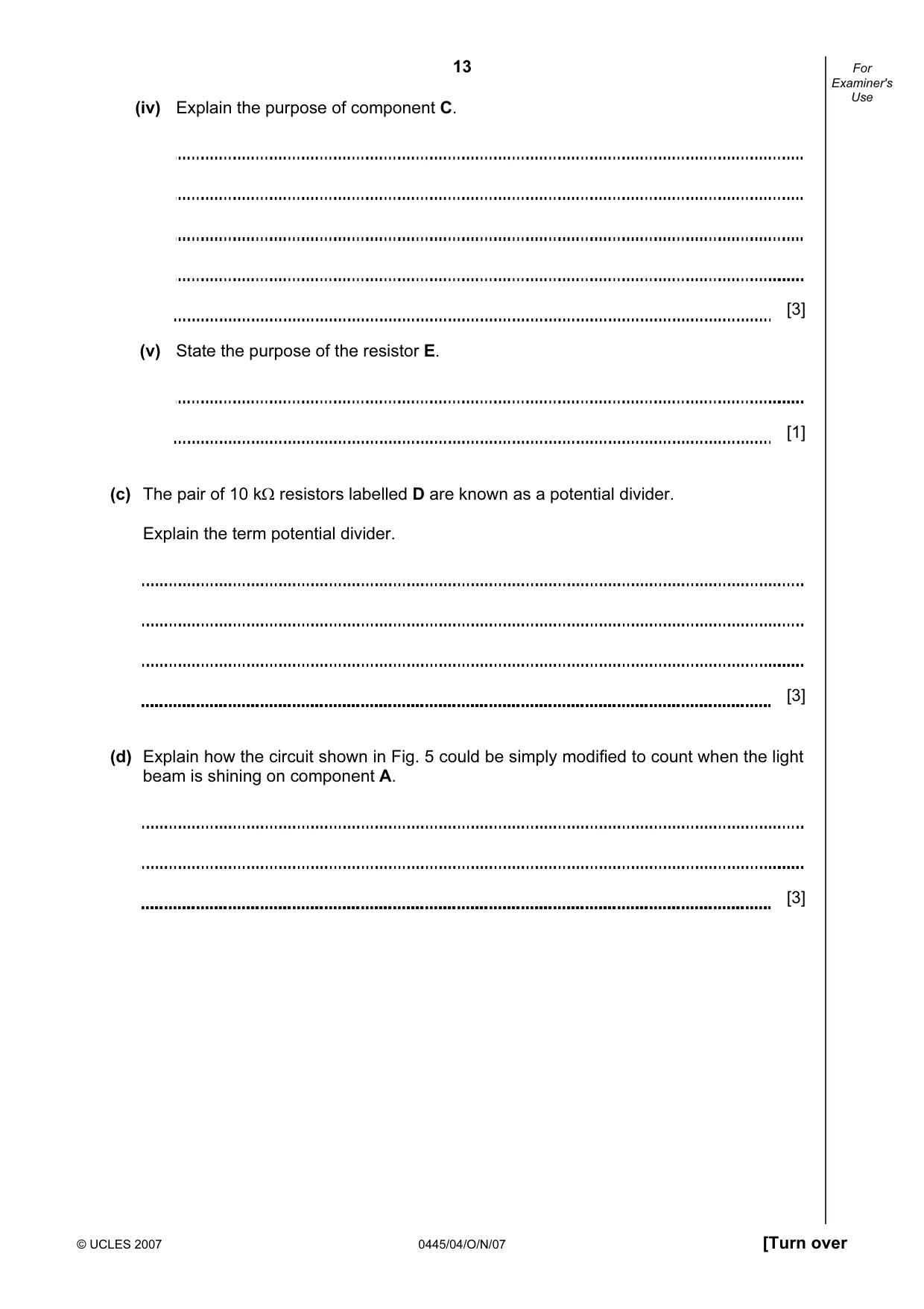
13 © UCLES 2007 0445/04/O/N/07 [Turn over For Examiner's Use (iv) Explain the purpose of component C. [3] (v) State the purpose of the resistor E. [1] (c) The pair of 10 kΩ resistors labelled D are known as a potential divider. Explain the term potential divider. [3] (d) Explain how the circuit shown in Fig. 5 could be simply modified to count when the light beam is shining on component A. [3]
Question paper, page 14
14 © UCLES 2007 0445/04/O/N/07 For Examiner's Use (e) Logic gates could be used to control a counter. Fig. 6 shows a pressure pad circuit that is used to trigger a counter when a person steps on pad P and, at the same time, presses the push button Q. counter P Q Fig. 6 (i) Complete the truth table below for this logic circuit. Pad P On/Off Pad Q On/Off Counter state On/Off Off Off Off Off On On Off On [4] (ii) Identify the type of logic circuit shown. [1]
Question paper, page 16
16 Permission to reproduce items where third-party owned material protected by copyright is included has been sought and cleared where possible. Every reasonable effort has been made by the publisher (UCLES) to trace copyright holders, but if any items requiring clearance have unwittingly been included, the publisher will be pleased to make amends at the earliest possible opportunity. University of Cambridge International Examinations is part of the Cambridge Assessment Group. Cambridge Assessment is the brand name of University of Cambridge Local Examinations Syndicate (UCLES), which is itself a department of the University of Cambridge. 0445/04/O/N/07 BLANK PAGE
Mark scheme, page 1
UNIVERSITY OF CAMBRIDGE INTERNATIONAL EXAMINATIONS International General Certificate of Secondary Education MARK SCHEME for the October/November 2007 question paper 0445 DESIGN AND TECHNOLOGY 0445/04 Paper 4 (Technology), maximum raw mark 50 This mark scheme is published as an aid to teachers and candidates, to indicate the requirements of the examination. It shows the basis on which Examiners were instructed to award marks. It does not indicate the details of the discussions that took place at an Examiners’ meeting before marking began. All Examiners are instructed that alternative correct answers and unexpected approaches in candidates’ scripts must be given marks that fairly reflect the relevant knowledge and skills demonstrated. Mark schemes must be read in conjunction with the question papers and the report on the examination. • CIE will not enter into discussions or correspondence in connection with these mark schemes. CIE is publishing the mark schemes for the October/November 2007 question papers for most IGCSE, GCE Advanced Level and Advanced Subsidiary Level syllabuses and some Ordinary Level syllabuses. www.XtremePapers.com
Mark scheme, page 2
Page 2 Mark Scheme Syllabus Paper IGCSE – October/November 2007 0445 04 © UCLES 2007 Section A 1 Tensile [1] 2 Electrolytic (1) capacitor (1) Time delay circuit (1) [3] 3 Name Diagram Use Pear cam and flat follower Valve operation Sprocket and Chain (Chain drive) (1) Bicycle transmission [3] 4 Second [1] An example: Wheelbarrow/Nutcrackers/Brake pedal [1] 5 (a) [2] (b) Linear [1] (c) Change direction (1) without change of value (1) [2] (1) (1) (1) (1) (1)
Mark scheme, page 3
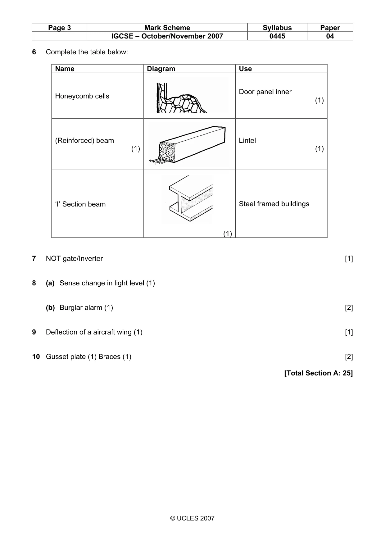
Page 3 Mark Scheme Syllabus Paper IGCSE – October/November 2007 0445 04 © UCLES 2007 6 Complete the table below: Name Diagram Use Honeycomb cells Door panel inner (1) (Reinforced) beam (1) Lintel (1) ‘I’ Section beam (1) Steel framed buildings 7 NOT gate/Inverter [1] 8 (a) Sense change in light level (1) (b) Burglar alarm (1) [2] 9 Deflection of a aircraft wing (1) [1] 10 Gusset plate (1) Braces (1) [2] [Total Section A: 25]
Mark scheme, page 4
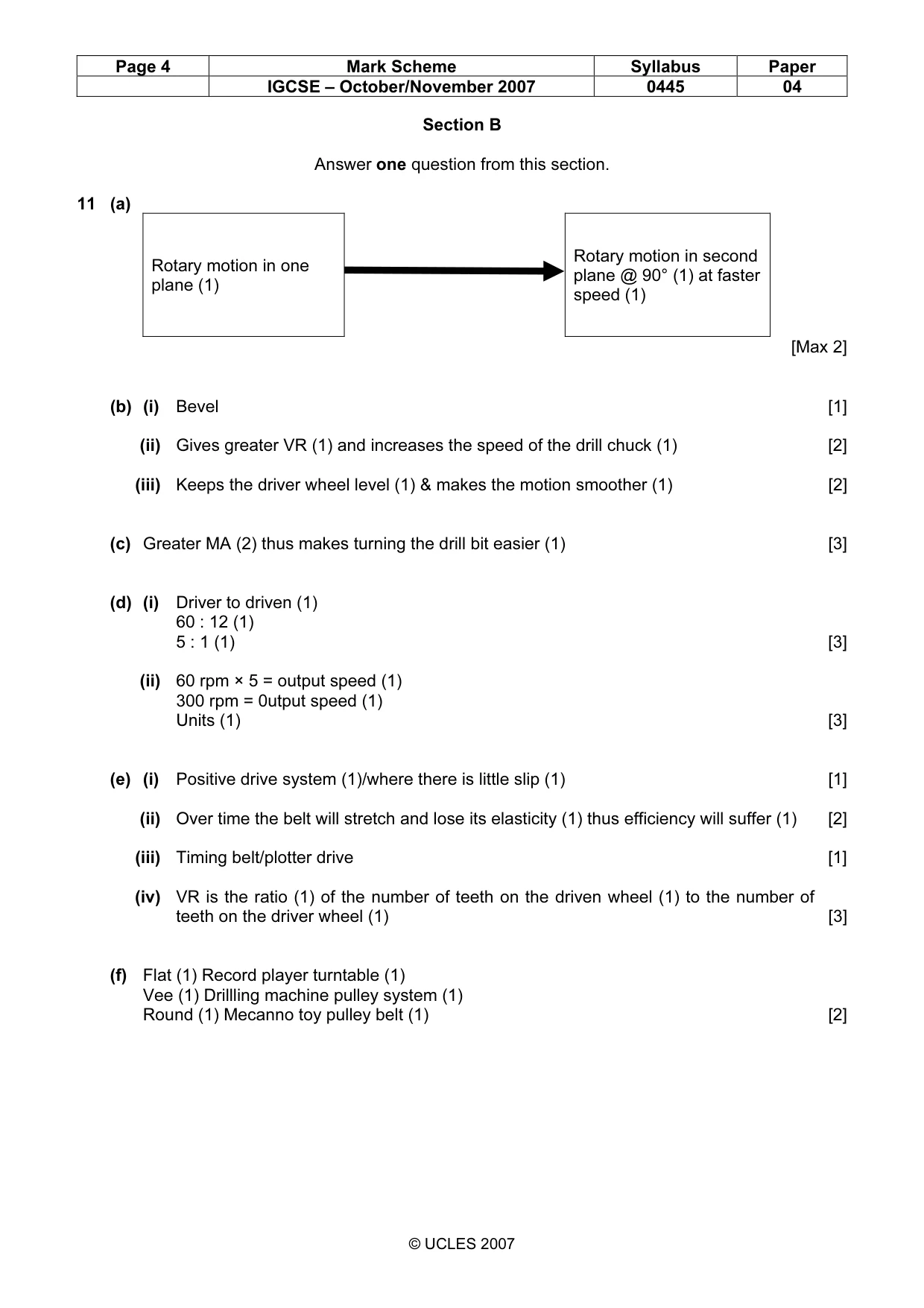
Page 4 Mark Scheme Syllabus Paper IGCSE – October/November 2007 0445 04 © UCLES 2007 Section B Answer one question from this section. 11 (a) Rotary motion in one plane (1) Rotary motion in second plane @ 90° (1) at faster speed (1) [Max 2] (b) (i) Bevel [1] (ii) Gives greater VR (1) and increases the speed of the drill chuck (1) [2] (iii) Keeps the driver wheel level (1) & makes the motion smoother (1) [2] (c) Greater MA (2) thus makes turning the drill bit easier (1) [3] (d) (i) Driver to driven (1) 60 : 12 (1) 5 : 1 (1) [3] (ii) 60 rpm × 5 = output speed (1) 300 rpm = 0utput speed (1) Units (1) [3] (e) (i) Positive drive system (1)/where there is little slip (1) [1] (ii) Over time the belt will stretch and lose its elasticity (1) thus efficiency will suffer (1) [2] (iii) Timing belt/plotter drive [1] (iv) VR is the ratio (1) of the number of teeth on the driven wheel (1) to the number of teeth on the driver wheel (1) [3] (f) Flat (1) Record player turntable (1) Vee (1) Drillling machine pulley system (1) Round (1) Mecanno toy pulley belt (1) [2]
Mark scheme, page 5
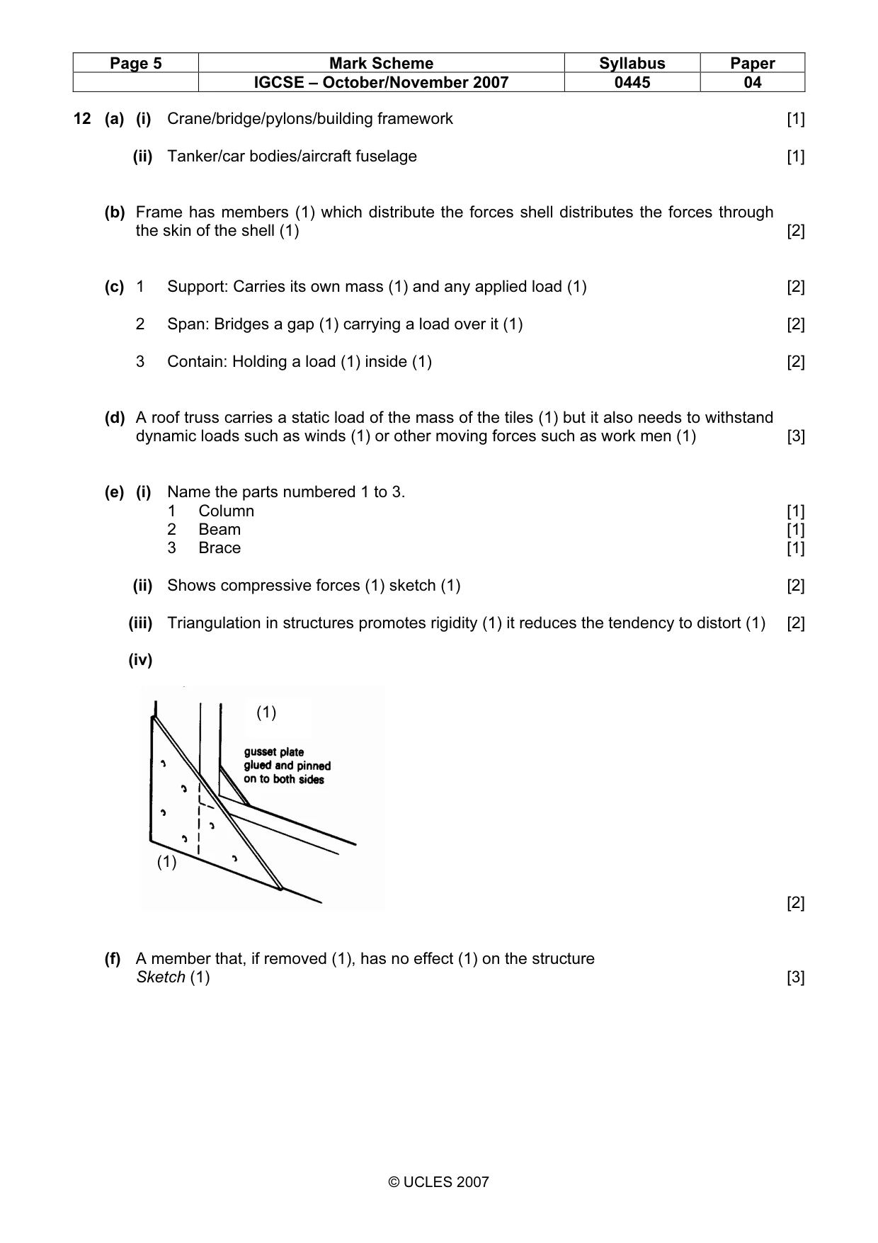
Page 5 Mark Scheme Syllabus Paper IGCSE – October/November 2007 0445 04 © UCLES 2007 12 (a) (i) Crane/bridge/pylons/building framework [1] (ii) Tanker/car bodies/aircraft fuselage [1] (b) Frame has members (1) which distribute the forces shell distributes the forces through the skin of the shell (1) [2] (c) 1 Support: Carries its own mass (1) and any applied load (1) [2] 2 Span: Bridges a gap (1) carrying a load over it (1) [2] 3 Contain: Holding a load (1) inside (1) [2] (d) A roof truss carries a static load of the mass of the tiles (1) but it also needs to withstand dynamic loads such as winds (1) or other moving forces such as work men (1) [3] (e) (i) Name the parts numbered 1 to 3. 1 Column [1] 2 Beam [1] 3 Brace [1] (ii) Shows compressive forces (1) sketch (1) [2] (iii) Triangulation in structures promotes rigidity (1) it reduces the tendency to distort (1) [2] (iv) [2] (f) A member that, if removed (1), has no effect (1) on the structure Sketch (1) [3] (1) (1)
Mark scheme, page 6
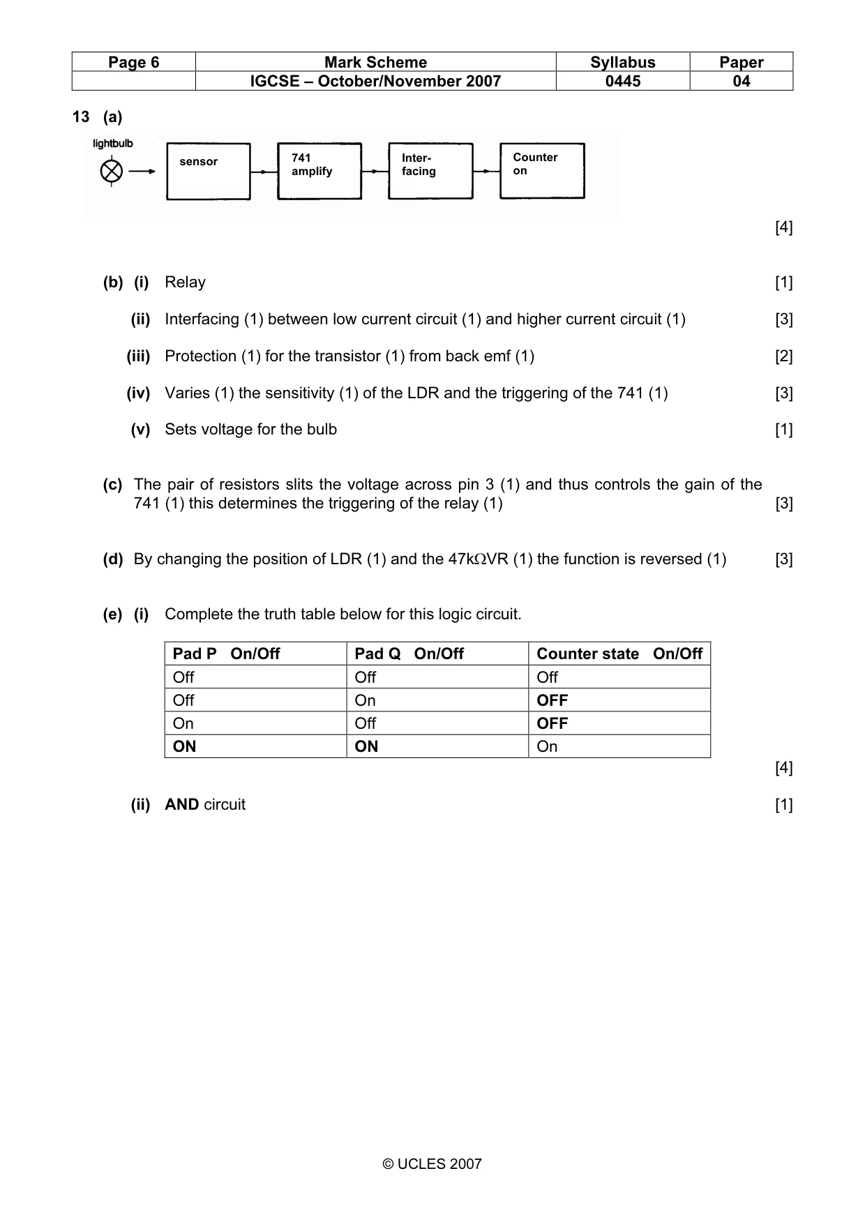
Page 6 Mark Scheme Syllabus Paper IGCSE – October/November 2007 0445 04 © UCLES 2007 13 (a) [4] (b) (i) Relay [1] (ii) Interfacing (1) between low current circuit (1) and higher current circuit (1) [3] (iii) Protection (1) for the transistor (1) from back emf (1) [2] (iv) Varies (1) the sensitivity (1) of the LDR and the triggering of the 741 (1) [3] (v) Sets voltage for the bulb [1] (c) The pair of resistors slits the voltage across pin 3 (1) and thus controls the gain of the 741 (1) this determines the triggering of the relay (1) [3] (d) By changing the position of LDR (1) and the 47kΩVR (1) the function is reversed (1) [3] (e) (i) Complete the truth table below for this logic circuit. Pad P On/Off Pad Q On/Off Counter state On/Off Off Off Off Off On OFF On Off OFF ON ON On [4] (ii) AND circuit [1] sensor 741 amplify Inter- facing Counter on
What you needed in this session
Cambridge’s own grade thresholds for 2007 Oct/Nov, Paper 4 · Variant 1. A higher threshold means an easier paper — the bar moves with how the cohort did.