Cambridge IGCSE Design and Technology 0445 — 2007 May/June Paper 4 · Variant 1
0445/41/M/J/07 · 50 marks · ≈56 min
The question paper and its mark scheme, free to read here and free to download. This is Cambridge’s own paper, exactly as it was sat.
Question paper20 pages


Mark scheme7 pages
Answers below. Sit the paper first if you are practising.
Paper as text
Question paper, page 1
This document consists of 18 printed pages and 2 blank pages. IB07 06_0445_04/4RP © UCLES 2007 [Turn over *1931934497* For Examiner's Use Section A Section B Total UNIVERSITY OF CAMBRIDGE INTERNATIONAL EXAMINATIONS International General Certificate of Secondary Education DESIGN AND TECHNOLOGY 0445/04 Paper 4 Systems and Control May/June 2007 1 hour Candidates answer on the Question Paper. No Additional Materials are required. To be taken together with Paper 1 in one session of 2 hours 15 minutes. READ THESE INSTRUCTIONS FIRST Write your Centre number, candidate number and name on all the work you hand in. Write in dark blue or black pen. You may use a soft pencil for any diagrams or graphs. Do not use staples, paper clips, highlighters, glue or correction fluid. DO NOT WRITE IN ANY BARCODES. You may use a calculator. Section A Answer all questions. Section B Answer one question. At the end of the examination, fasten all your work securely together. The number of marks is given in brackets [ ] at the end of each question or part question. www.XtremePapers.com
Question paper, page 2
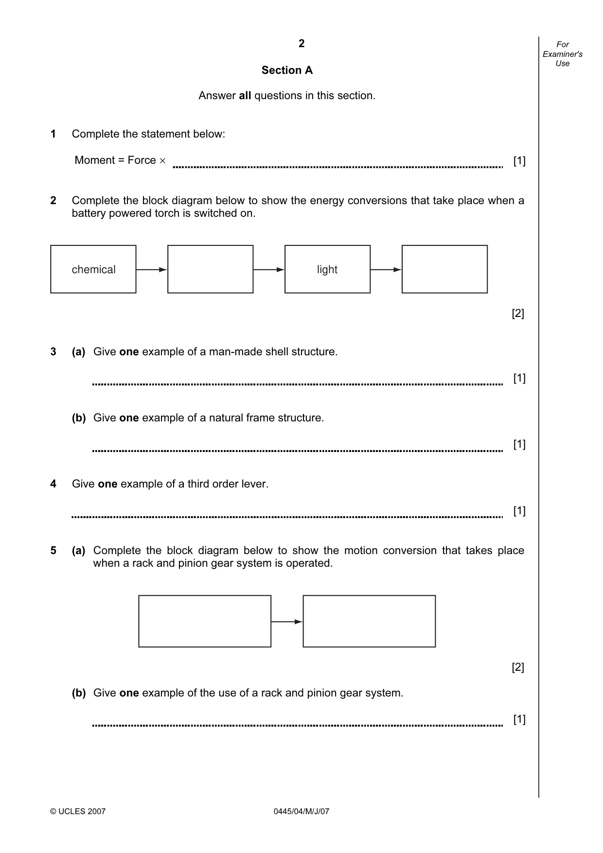
2 © UCLES 2007 0445/04/M/J/07 For Examiner's Use Section A Answer all questions in this section. 1 Complete the statement below: Moment = Force × [1] 2 Complete the block diagram below to show the energy conversions that take place when a battery powered torch is switched on. chemical light [2] 3 (a) Give one example of a man-made shell structure. [1] (b) Give one example of a natural frame structure. [1] 4 Give one example of a third order lever. [1] 5 (a) Complete the block diagram below to show the motion conversion that takes place when a rack and pinion gear system is operated. [2] (b) Give one example of the use of a rack and pinion gear system. [1]
Question paper, page 3
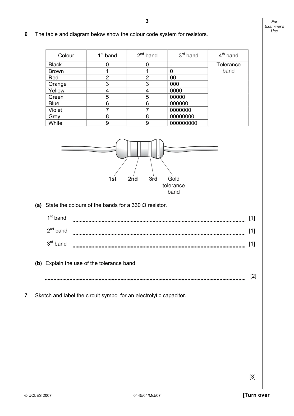
3 © UCLES 2007 0445/04/M/J/07 [Turn over For Examiner's Use 6 The table and diagram below show the colour code system for resistors. Colour 1st band 2nd band 3rd band 4th band Black 0 0 - Brown 1 1 0 Red 2 2 00 Orange 3 3 000 Yellow 4 4 0000 Green 5 5 00000 Blue 6 6 000000 Violet 7 7 0000000 Grey 8 8 00000000 White 9 9 000000000 Tolerance band 1st 2nd 3rd Gold tolerance band (a) State the colours of the bands for a 330 Ω resistor. 1st band [1] 2nd band [1] 3rd band [1] (b) Explain the use of the tolerance band. [2] 7 Sketch and label the circuit symbol for an electrolytic capacitor. [3]
Question paper, page 4
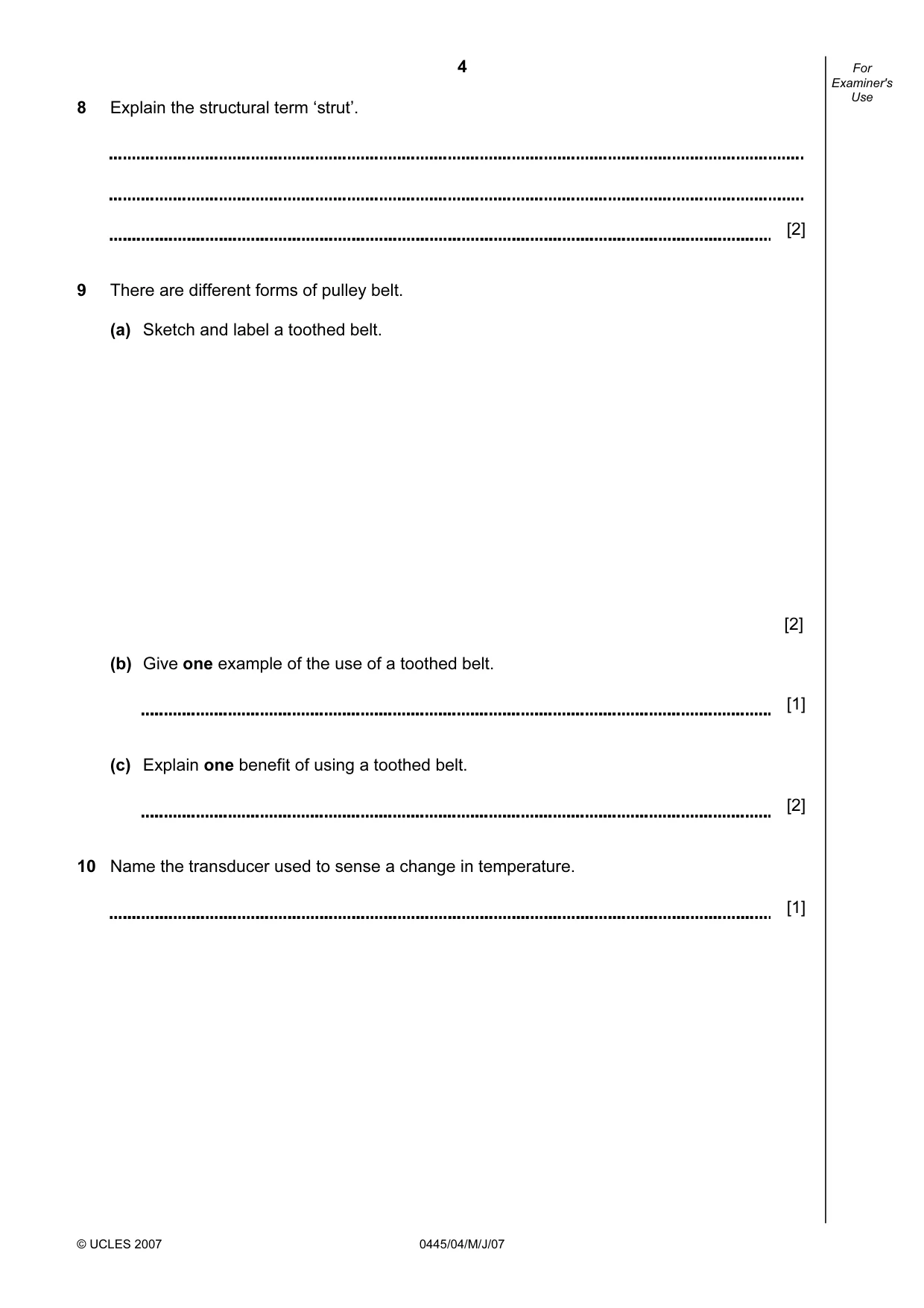
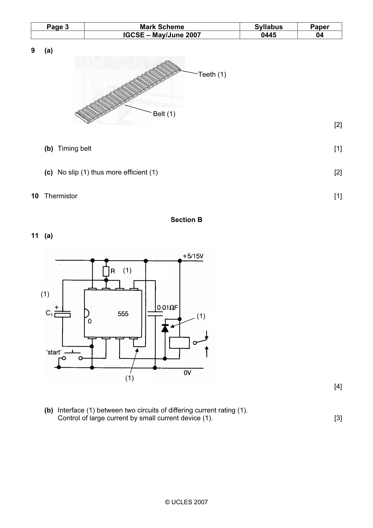
4 © UCLES 2007 0445/04/M/J/07 For Examiner's Use 8 Explain the structural term ‘strut’. [2] 9 There are different forms of pulley belt. (a) Sketch and label a toothed belt. [2] (b) Give one example of the use of a toothed belt. [1] (c) Explain one benefit of using a toothed belt. [2] 10 Name the transducer used to sense a change in temperature. [1]
Question paper, page 5
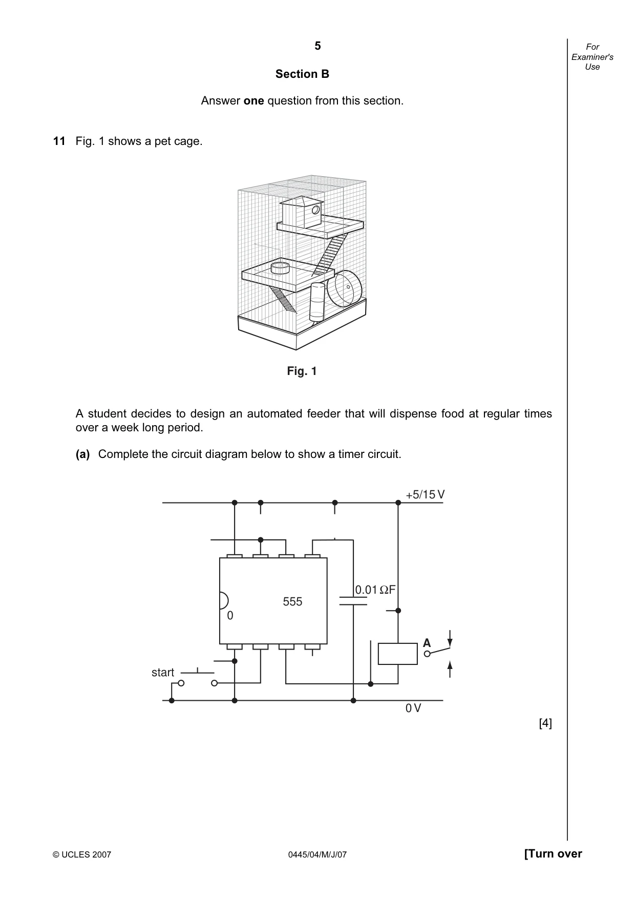
5 © UCLES 2007 0445/04/M/J/07 [Turn over For Examiner's Use Section B Answer one question from this section. 11 Fig. 1 shows a pet cage. Fig. 1 A student decides to design an automated feeder that will dispense food at regular times over a week long period. (a) Complete the circuit diagram below to show a timer circuit. 0.01 ΩF A start 0 V +5/15 V 0 555 [4]
Question paper, page 6
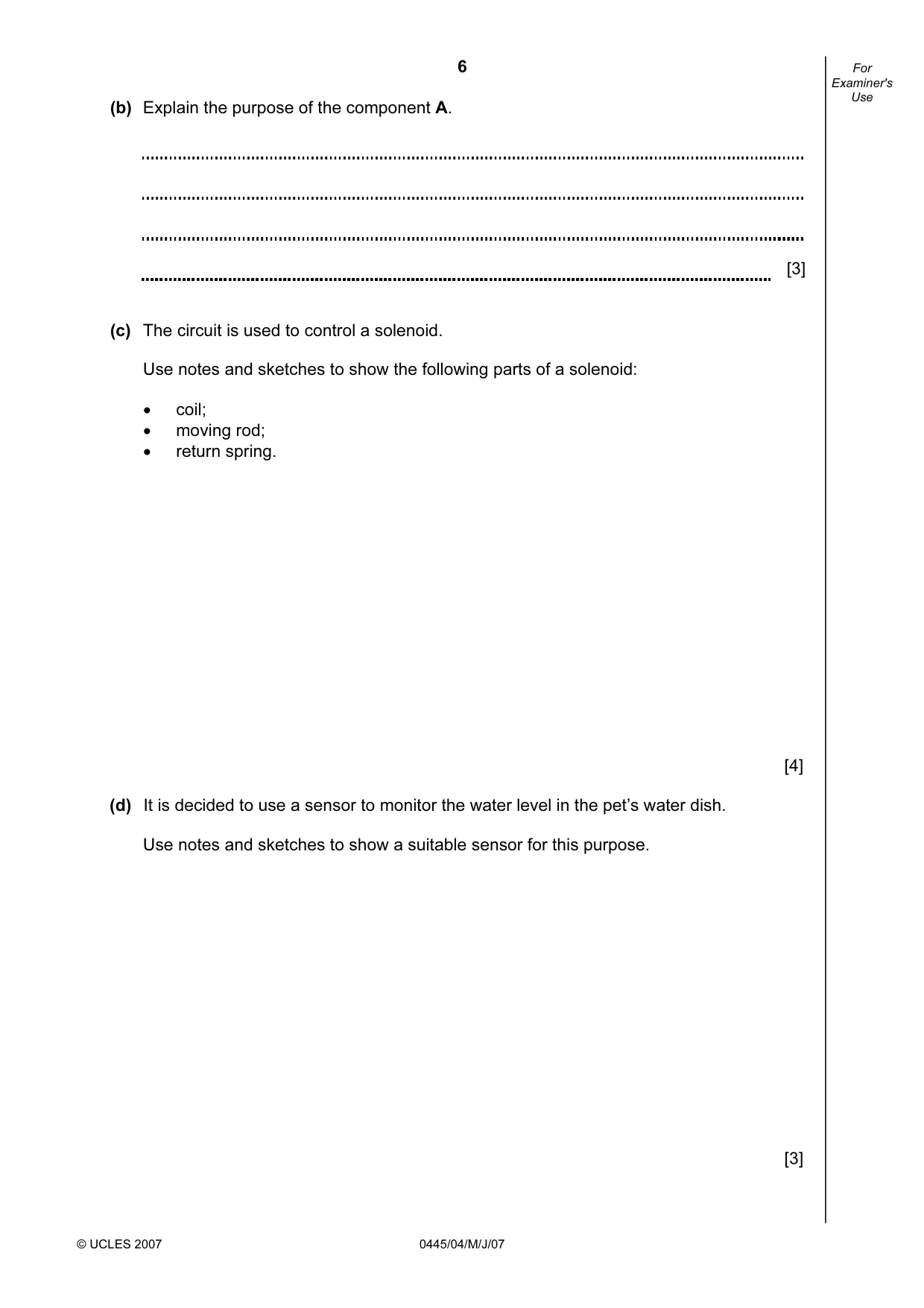
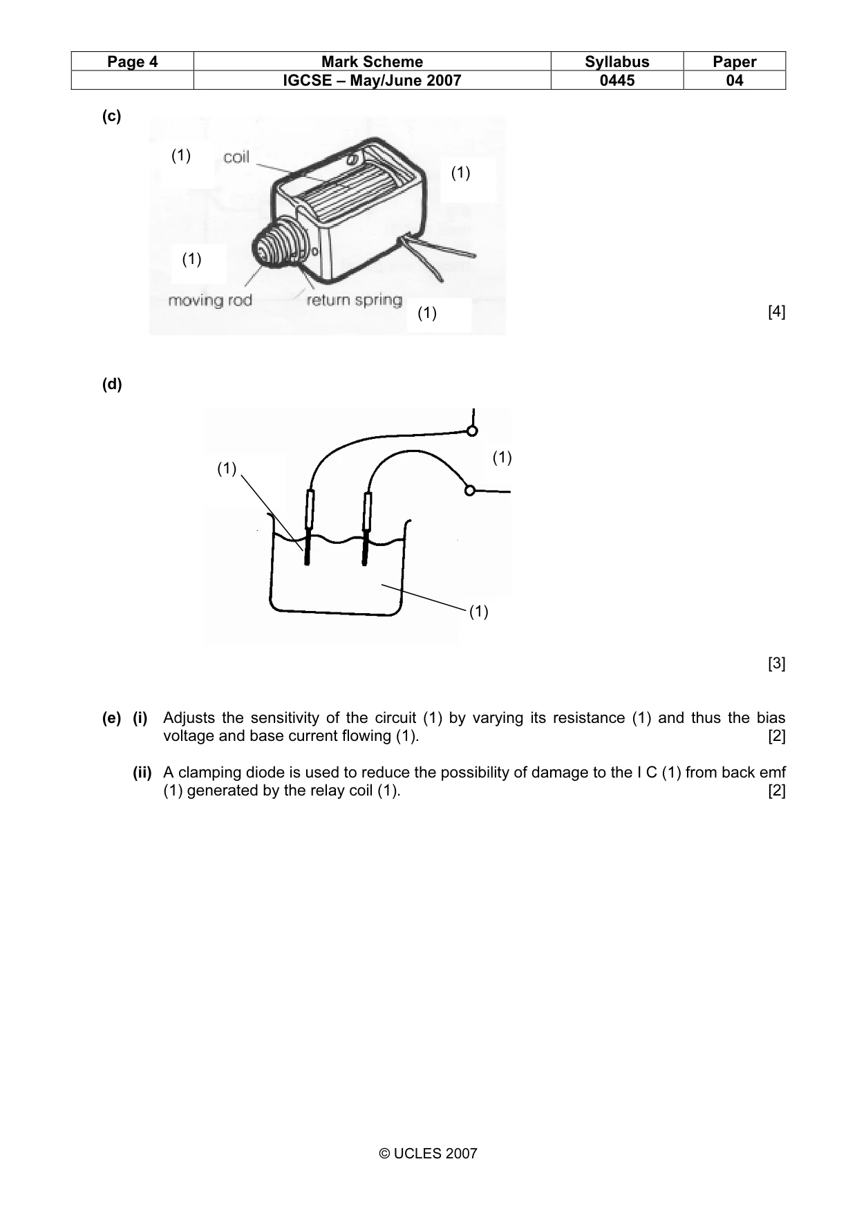
6 © UCLES 2007 0445/04/M/J/07 For Examiner's Use (b) Explain the purpose of the component A. [3] (c) The circuit is used to control a solenoid. Use notes and sketches to show the following parts of a solenoid: • coil; • moving rod; • return spring. [4] (d) It is decided to use a sensor to monitor the water level in the pet’s water dish. Use notes and sketches to show a suitable sensor for this purpose. [3]
Question paper, page 7
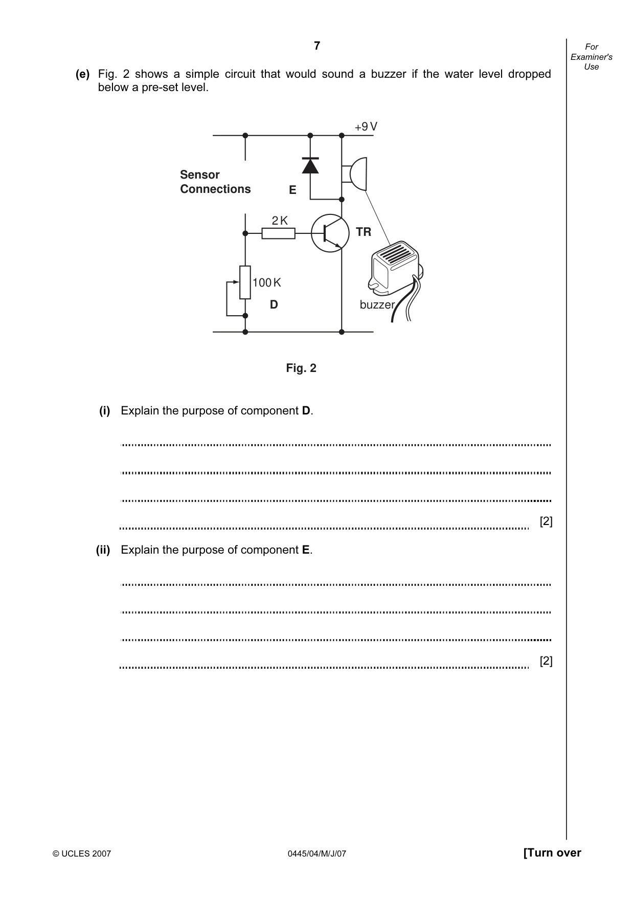
7 © UCLES 2007 0445/04/M/J/07 [Turn over For Examiner's Use (e) Fig. 2 shows a simple circuit that would sound a buzzer if the water level dropped below a pre-set level. 2 K 100 K D E Sensor Connections TR buzzer +9 V Fig. 2 (i) Explain the purpose of component D. [2] (ii) Explain the purpose of component E. [2]
Question paper, page 8
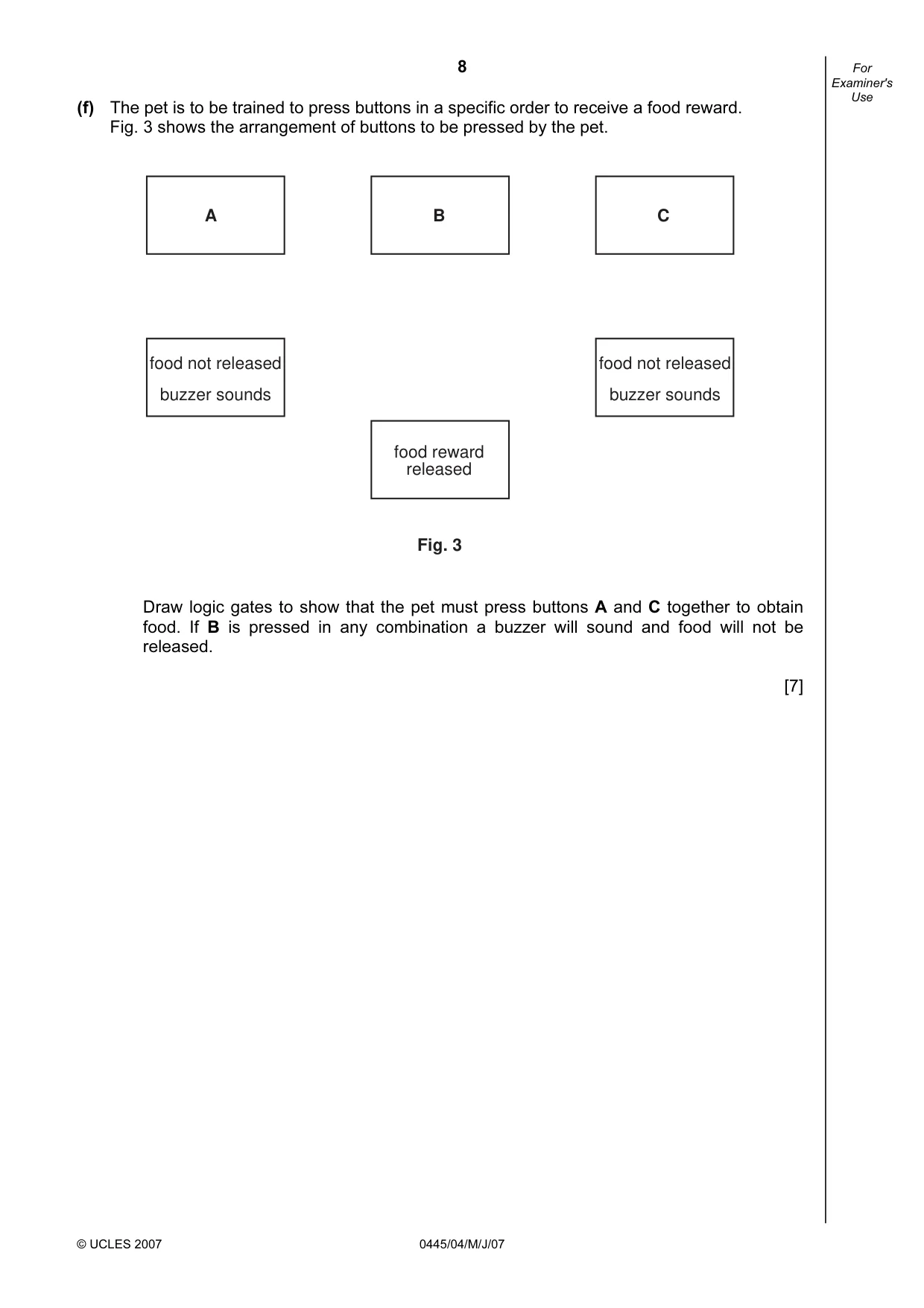
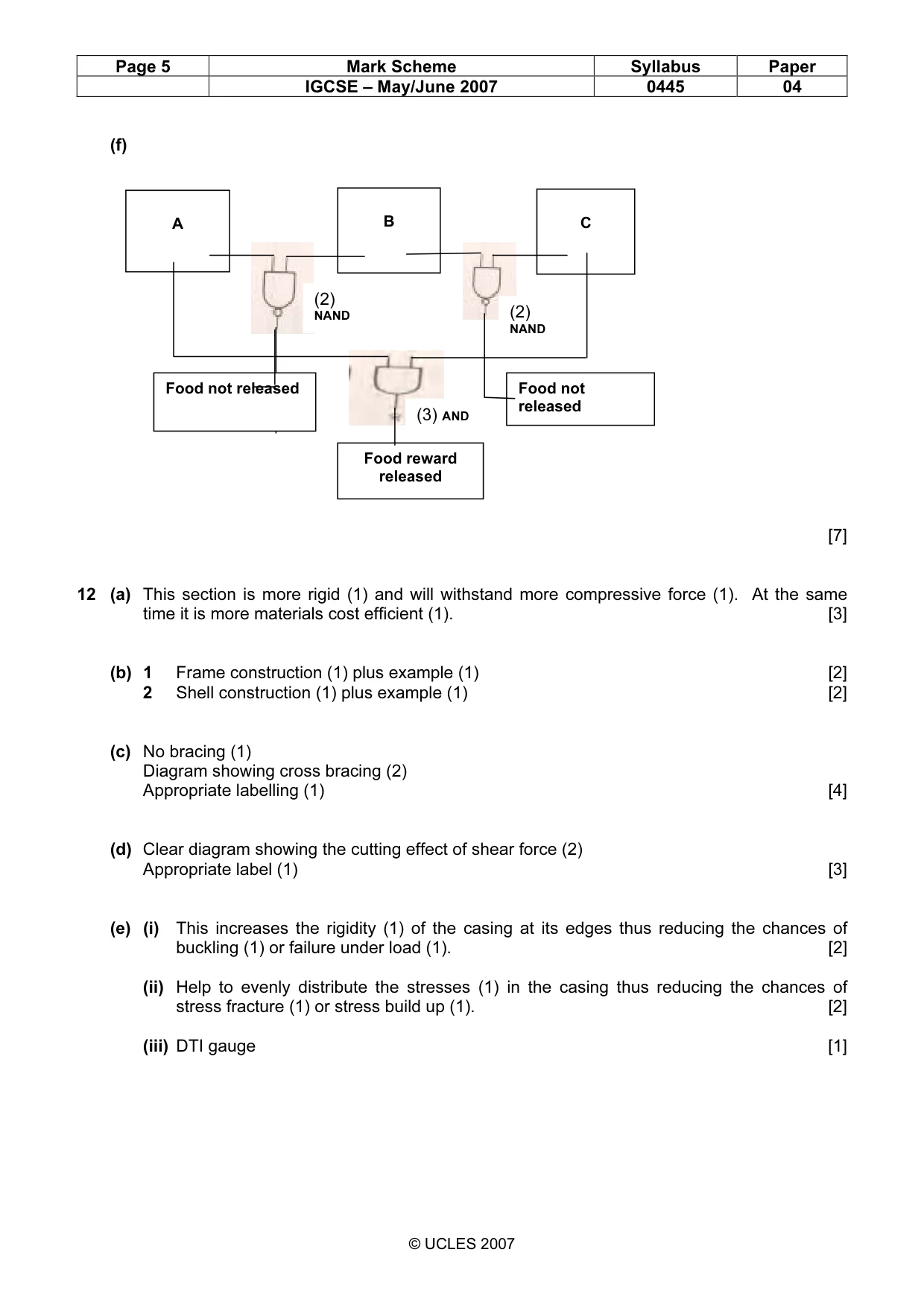
8 © UCLES 2007 0445/04/M/J/07 For Examiner's Use (f) The pet is to be trained to press buttons in a specific order to receive a food reward. Fig. 3 shows the arrangement of buttons to be pressed by the pet. A B C food not released buzzer sounds food not released buzzer sounds food reward released Fig. 3 Draw logic gates to show that the pet must press buttons A and C together to obtain food. If B is pressed in any combination a buzzer will sound and food will not be released. [7]
Question paper, page 9
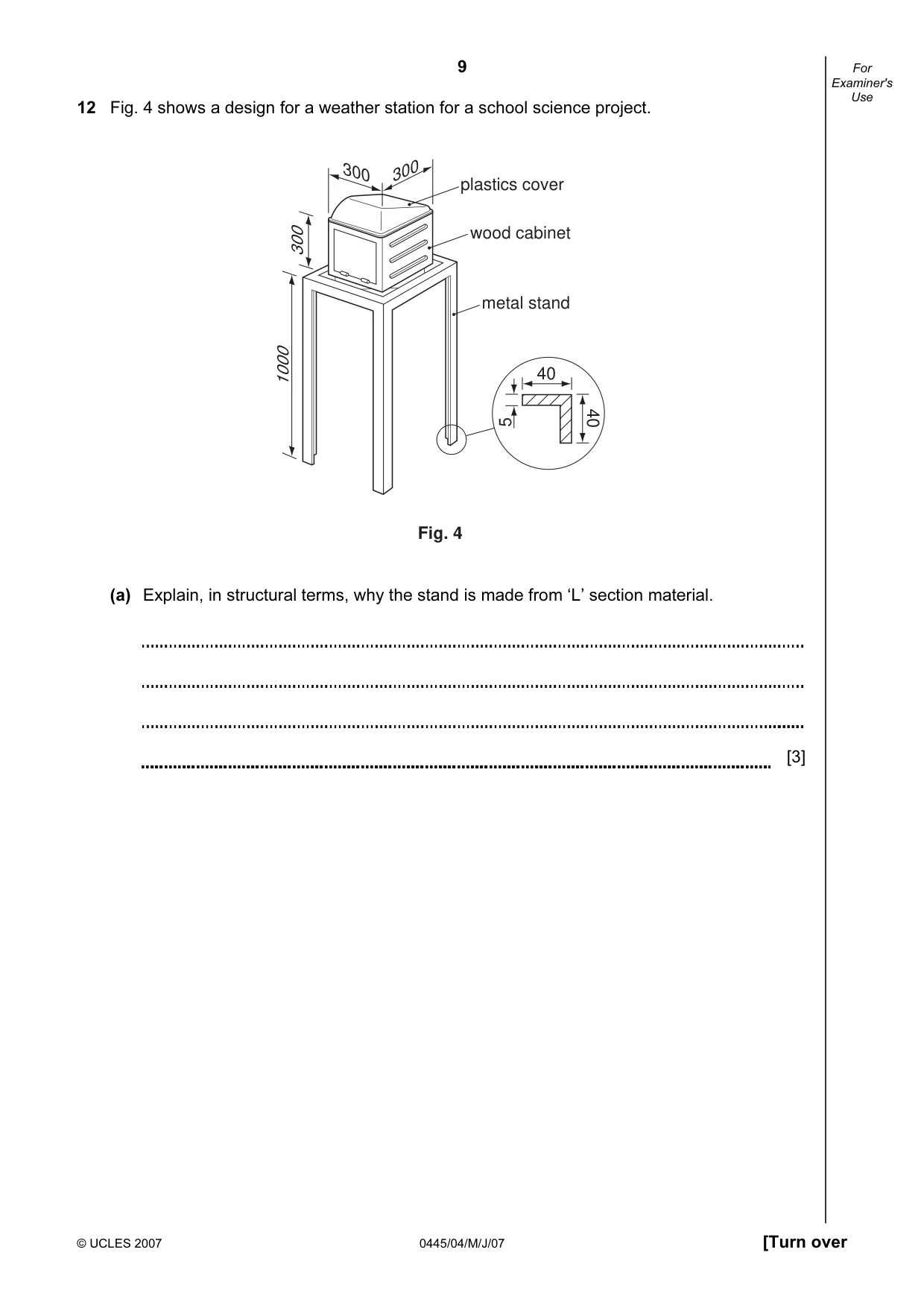
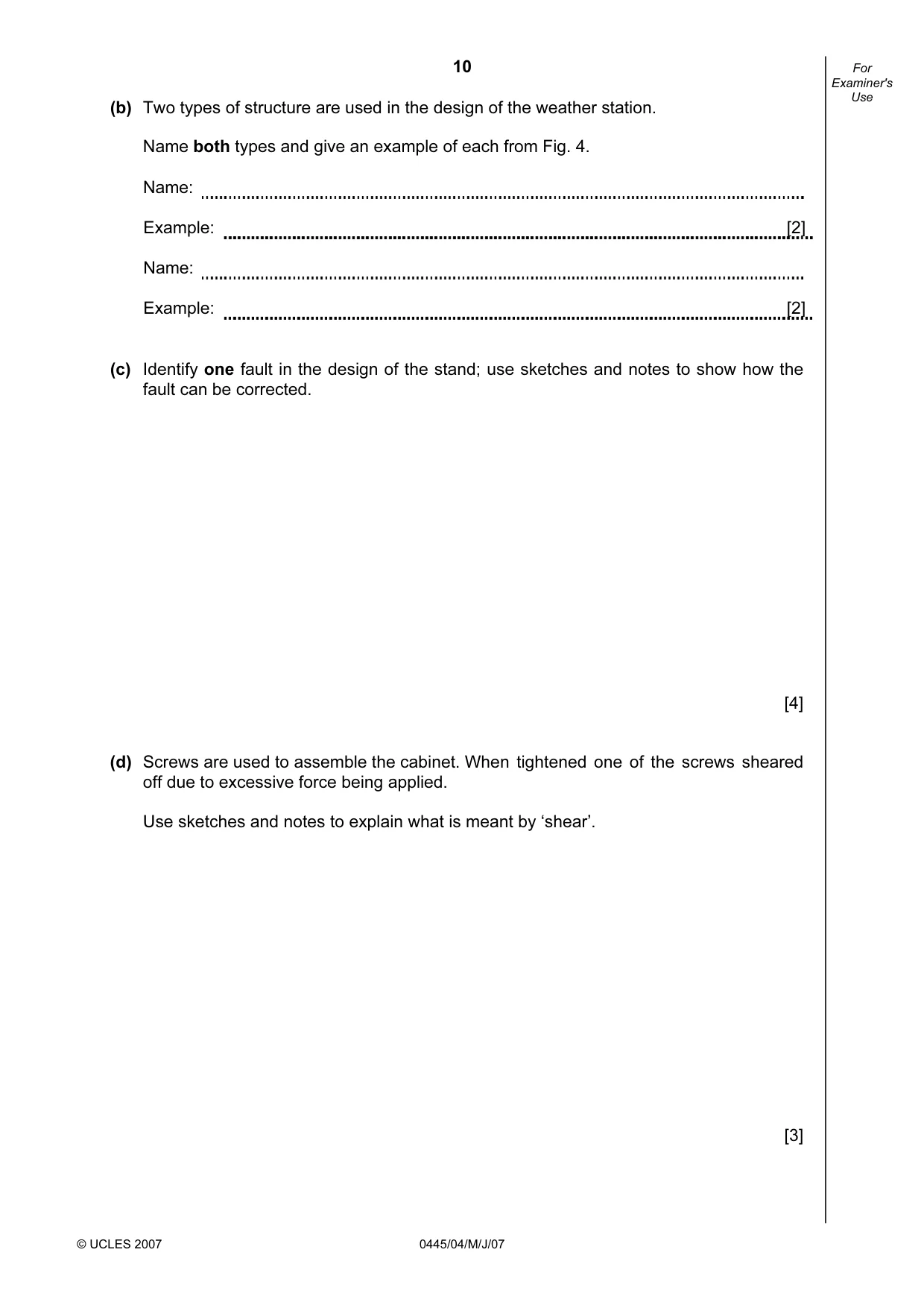
9 © UCLES 2007 0445/04/M/J/07 [Turn over For Examiner's Use 12 Fig. 4 shows a design for a weather station for a school science project. plastics cover wood cabinet metal stand 1000 300 300 300 40 40 5 Fig. 4 (a) Explain, in structural terms, why the stand is made from ‘L’ section material. [3]
Question paper, page 10
10 © UCLES 2007 0445/04/M/J/07 For Examiner's Use (b) Two types of structure are used in the design of the weather station. Name both types and give an example of each from Fig. 4. Name: Example: [2] Name: Example: [2] (c) Identify one fault in the design of the stand; use sketches and notes to show how the fault can be corrected. [4] (d) Screws are used to assemble the cabinet. When tightened one of the screws sheared off due to excessive force being applied. Use sketches and notes to explain what is meant by ‘shear’. [3]
Question paper, page 11
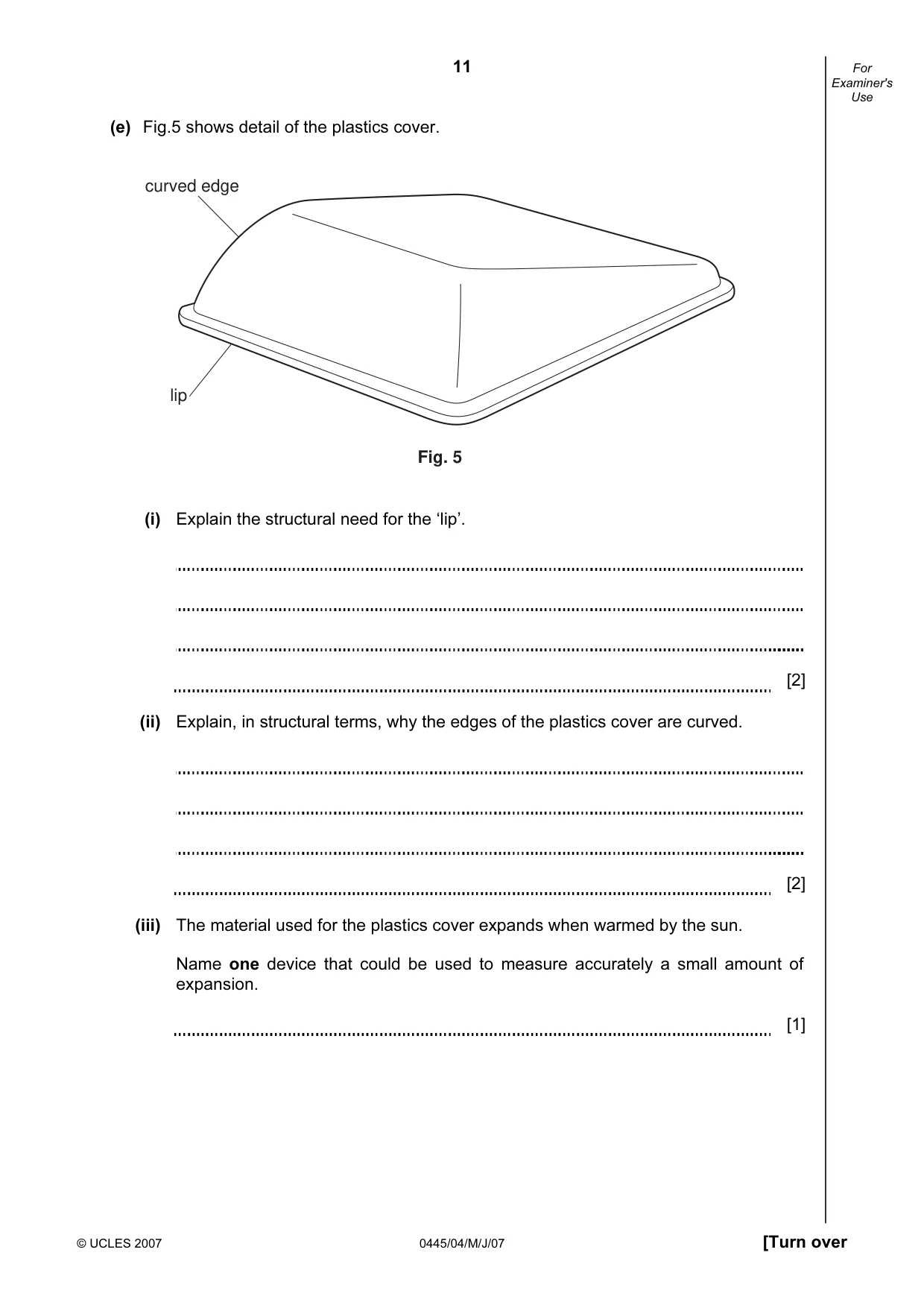
11 © UCLES 2007 0445/04/M/J/07 [Turn over For Examiner's Use (e) Fig.5 shows detail of the plastics cover. lip Fig. 5 curved edge (i) Explain the structural need for the ‘lip’. [2] (ii) Explain, in structural terms, why the edges of the plastics cover are curved. [2] (iii) The material used for the plastics cover expands when warmed by the sun. Name one device that could be used to measure accurately a small amount of expansion. [1]
Question paper, page 12
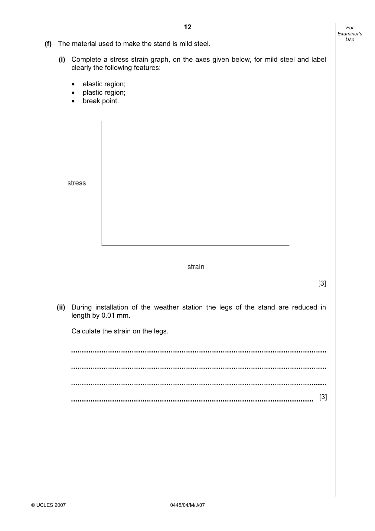
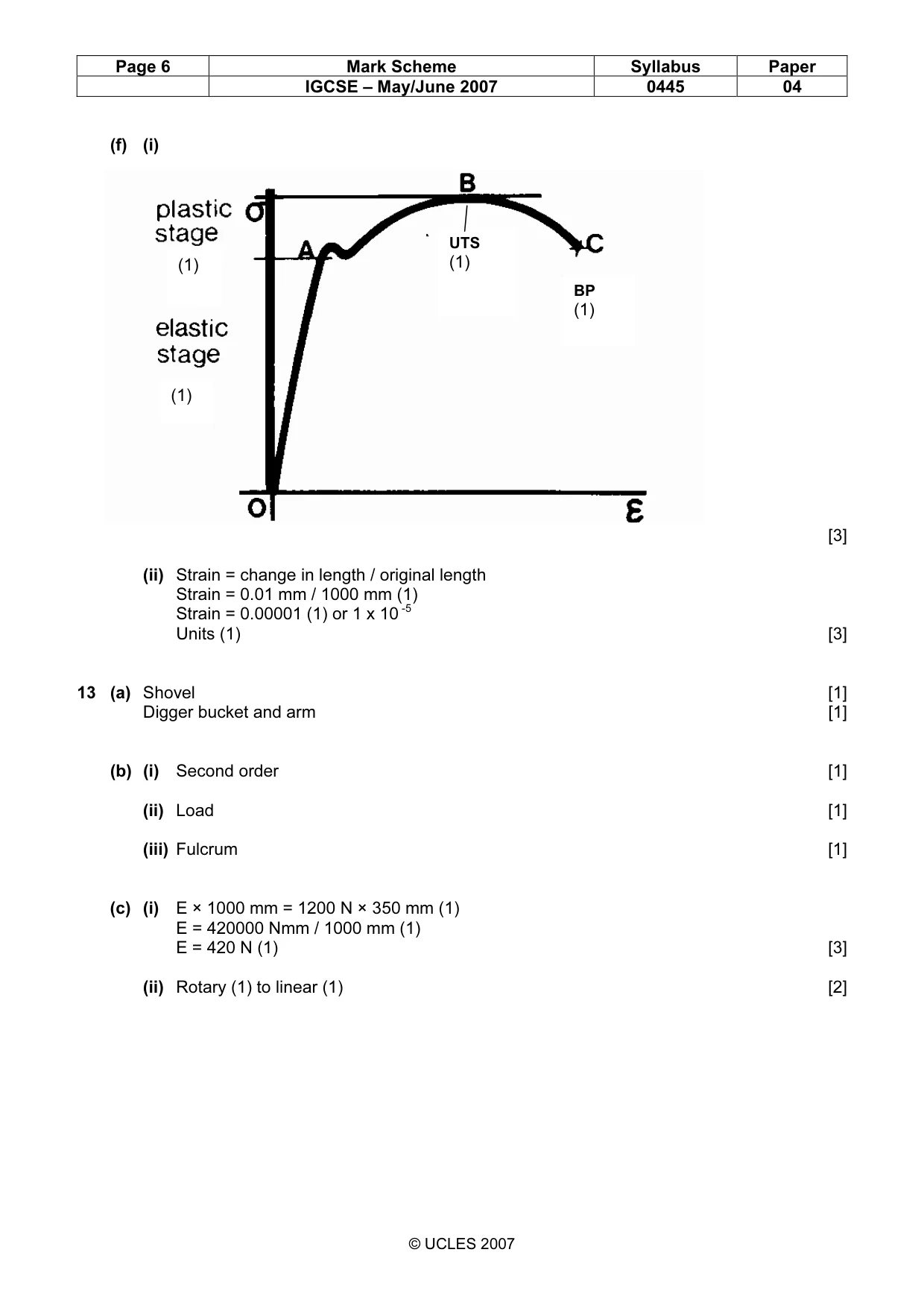
12 © UCLES 2007 0445/04/M/J/07 For Examiner's Use (f) The material used to make the stand is mild steel. (i) Complete a stress strain graph, on the axes given below, for mild steel and label clearly the following features: • elastic region; • plastic region; • break point. stress strain [3] (ii) During installation of the weather station the legs of the stand are reduced in length by 0.01 mm. Calculate the strain on the legs. [3]
Question paper, page 13
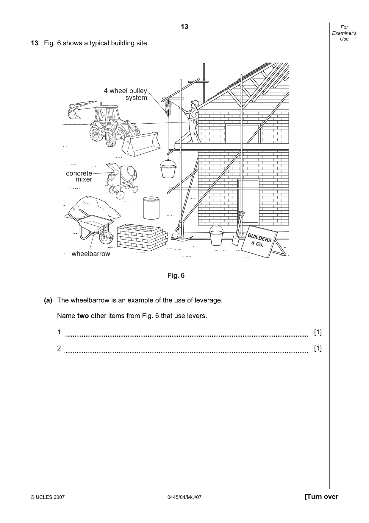
13 © UCLES 2007 0445/04/M/J/07 [Turn over For Examiner's Use 13 Fig. 6 shows a typical building site. concrete mixer 4 wheel pulley system wheelbarrow BUILDERS & Co. Fig. 6 (a) The wheelbarrow is an example of the use of leverage. Name two other items from Fig. 6 that use levers. 1 [1] 2 [1]
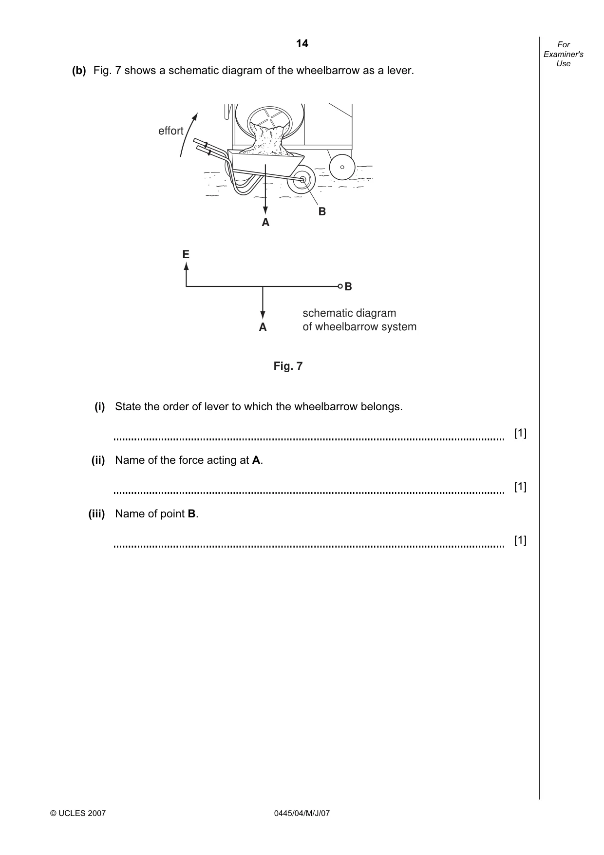
Question paper, page 14
14 © UCLES 2007 0445/04/M/J/07 For Examiner's Use (b) Fig. 7 shows a schematic diagram of the wheelbarrow as a lever. A B effort E A Fig. 7 schematic diagram of wheelbarrow system B (i) State the order of lever to which the wheelbarrow belongs. [1] (ii) Name of the force acting at A. [1] (iii) Name of point B. [1]
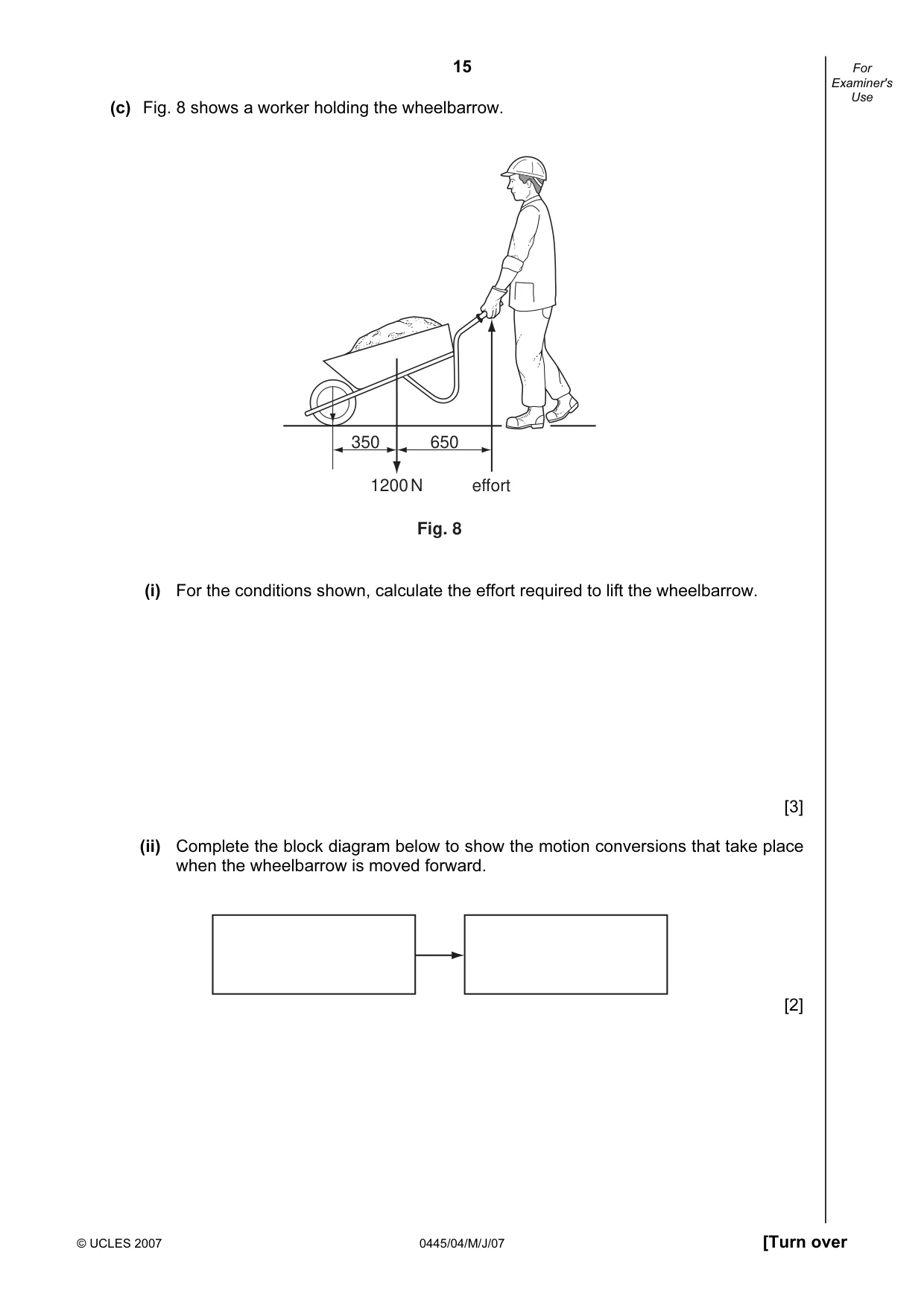
Question paper, page 15
15 © UCLES 2007 0445/04/M/J/07 [Turn over For Examiner's Use (c) Fig. 8 shows a worker holding the wheelbarrow. 350 650 1200 N effort Fig. 8 (i) For the conditions shown, calculate the effort required to lift the wheelbarrow. [3] (ii) Complete the block diagram below to show the motion conversions that take place when the wheelbarrow is moved forward. [2]
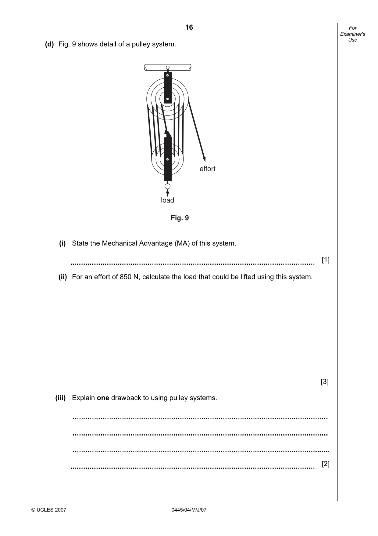
Question paper, page 16
16 © UCLES 2007 0445/04/M/J/07 For Examiner's Use (d) Fig. 9 shows detail of a pulley system. load effort Fig. 9 (i) State the Mechanical Advantage (MA) of this system. [1] (ii) For an effort of 850 N, calculate the load that could be lifted using this system. [3] (iii) Explain one drawback to using pulley systems. [2]
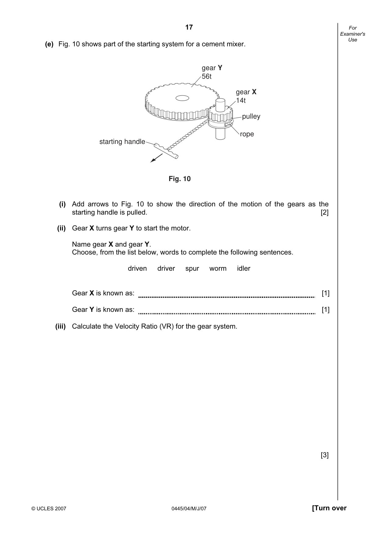
Question paper, page 17
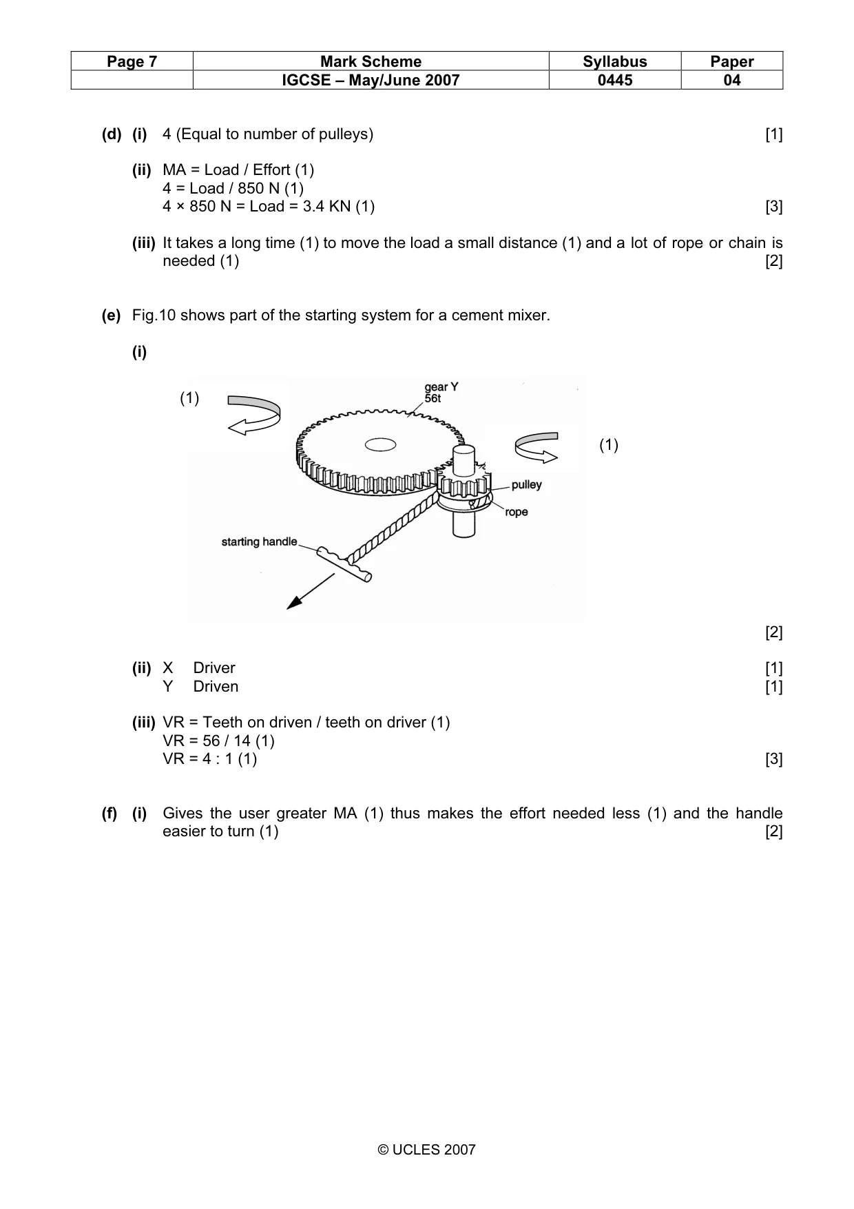
17 © UCLES 2007 0445/04/M/J/07 [Turn over For Examiner's Use (e) Fig. 10 shows part of the starting system for a cement mixer. gear Y 56t gear X 14t pulley rope starting handle Fig. 10 (i) Add arrows to Fig. 10 to show the direction of the motion of the gears as the starting handle is pulled. [2] (ii) Gear X turns gear Y to start the motor. Name gear X and gear Y. Choose, from the list below, words to complete the following sentences. driven driver spur worm idler Gear X is known as: [1] Gear Y is known as: [1] (iii) Calculate the Velocity Ratio (VR) for the gear system. [3]
Question paper, page 18
18 © UCLES 2007 0445/04/M/J/07 For Examiner's Use (f) Fig. 11 shows a cranked handle from a machine. machine wall cranked handle shaft hole Fig. 11 Explain why the handle is cranked. [2]
Question paper, page 20
20 Permission to reproduce items where third-party owned material protected by copyright is included has been sought and cleared where possible. Every reasonable effort has been made by the publisher (UCLES) to trace copyright holders, but if any items requiring clearance have unwittingly been included, the publisher will be pleased to make amends at the earliest possible opportunity. University of Cambridge International Examinations is part of the Cambridge Assessment Group. Cambridge Assessment is the brand name of University of Cambridge Local Examinations Syndicate (UCLES), which is itself a department of the University of Cambridge. 0445/04/M/J/07 BLANK PAGE
Mark scheme, page 1
UNIVERSITY OF CAMBRIDGE INTERNATIONAL EXAMINATIONS International General Certificate of Secondary Education MARK SCHEME for the May/June 2007 question paper 0445 DESIGN AND TECHNOLOGY 0445/04 Paper 4 (Systems and Control), maximum raw mark 50 This mark scheme is published as an aid to teachers and candidates, to indicate the requirements of the examination. It shows the basis on which Examiners were instructed to award marks. It does not indicate the details of the discussions that took place at an Examiners’ meeting before marking began. All Examiners are instructed that alternative correct answers and unexpected approaches in candidates’ scripts must be given marks that fairly reflect the relevant knowledge and skills demonstrated. Mark schemes must be read in conjunction with the question papers and the report on the examination. • CIE will not enter into discussions or correspondence in connection with these mark schemes. CIE is publishing the mark schemes for the May/June 2007 question papers for most IGCSE, GCE Advanced Level and Advanced Subsidiary Level syllabuses and some Ordinary Level syllabuses. www.XtremePapers.com
Mark scheme, page 2
Page 2 Mark Scheme Syllabus Paper IGCSE – May/June 2007 0445 04 © UCLES 2007 Section A Answer all questions in this section. 1 Distance [1] 2 Electrical (1) Heat (1) [2] 3 (a) Car body [1] (b) Animal skeleton [1] 4 Shovel / Fishing rod [1] 5 (a) Rotary (1) to Linear (1) [2] (b) Any suitable example [1] 6 (a) Orange (1) Orange (1) Brown (1) [3] (b) Accuracy (1) or tolerance (1) e.g. ± 5 % (1) [2] 7 [3] 8 A member (1) that experiences compressive load (1) [2] (1) (1) (1)
Mark scheme, page 3
Page 3 Mark Scheme Syllabus Paper IGCSE – May/June 2007 0445 04 © UCLES 2007 9 (a) [2] (b) Timing belt [1] (c) No slip (1) thus more efficient (1) [2] 10 Thermistor [1] Section B 11 (a) [4] (b) Interface (1) between two circuits of differing current rating (1). Control of large current by small current device (1). [3] (1) (1) (1) (1) Teeth (1) Belt (1)
Mark scheme, page 4
Page 4 Mark Scheme Syllabus Paper IGCSE – May/June 2007 0445 04 © UCLES 2007 (c) [4] (d) [3] (e) (i) Adjusts the sensitivity of the circuit (1) by varying its resistance (1) and thus the bias voltage and base current flowing (1). [2] (ii) A clamping diode is used to reduce the possibility of damage to the I C (1) from back emf (1) generated by the relay coil (1). [2] (1) (1) (1) (1) (1) (1) (1)
Mark scheme, page 5
Page 5 Mark Scheme Syllabus Paper IGCSE – May/June 2007 0445 04 © UCLES 2007 (f) [7] 12 (a) This section is more rigid (1) and will withstand more compressive force (1). At the same time it is more materials cost efficient (1). [3] (b) 1 Frame construction (1) plus example (1) [2] 2 Shell construction (1) plus example (1) [2] (c) No bracing (1) Diagram showing cross bracing (2) Appropriate labelling (1) [4] (d) Clear diagram showing the cutting effect of shear force (2) Appropriate label (1) [3] (e) (i) This increases the rigidity (1) of the casing at its edges thus reducing the chances of buckling (1) or failure under load (1). [2] (ii) Help to evenly distribute the stresses (1) in the casing thus reducing the chances of stress fracture (1) or stress build up (1). [2] (iii) DTI gauge [1] A B C Food reward released Food not released Food not released (3) AND (2) NAND (2) NAND
Mark scheme, page 6
Page 6 Mark Scheme Syllabus Paper IGCSE – May/June 2007 0445 04 © UCLES 2007 (f) (i) [3] (ii) Strain = change in length / original length Strain = 0.01 mm / 1000 mm (1) Strain = 0.00001 (1) or 1 x 10 -5 Units (1) [3] 13 (a) Shovel [1] Digger bucket and arm [1] (b) (i) Second order [1] (ii) Load [1] (iii) Fulcrum [1] (c) (i) E × 1000 mm = 1200 N × 350 mm (1) E = 420000 Nmm / 1000 mm (1) E = 420 N (1) [3] (ii) Rotary (1) to linear (1) [2] UTS (1) BP (1) (1) (1)
Mark scheme, page 7
Page 7 Mark Scheme Syllabus Paper IGCSE – May/June 2007 0445 04 © UCLES 2007 (d) (i) 4 (Equal to number of pulleys) [1] (ii) MA = Load / Effort (1) 4 = Load / 850 N (1) 4 × 850 N = Load = 3.4 KN (1) [3] (iii) It takes a long time (1) to move the load a small distance (1) and a lot of rope or chain is needed (1) [2] (e) Fig.10 shows part of the starting system for a cement mixer. (i) [2] (ii) X Driver [1] Y Driven [1] (iii) VR = Teeth on driven / teeth on driver (1) VR = 56 / 14 (1) VR = 4 : 1 (1) [3] (f) (i) Gives the user greater MA (1) thus makes the effort needed less (1) and the handle easier to turn (1) [2] (1) (1)
What you needed in this session
Cambridge’s own grade thresholds for 2007 May/June, Paper 4 · Variant 1. A higher threshold means an easier paper — the bar moves with how the cohort did.