Cambridge IGCSE Design and Technology 0445 — 2006 Oct/Nov Paper 4 · Variant 1
0445/41/O/N/06
The question paper and its mark scheme, free to read here and free to download. This is Cambridge’s own paper, exactly as it was sat.
Question paper20 pages



Mark scheme6 pages
Answers below. Sit the paper first if you are practising.
Paper as text
Question paper, page 1
Centre Number Candidate Number Name UNIVERSITY OF CAMBRIDGE INTERNATIONAL EXAMINATIONS International General Certificate of Secondary Education DESIGN AND TECHNOLOGY 0445/04 Paper 4 Technology October/November 2006 1 hour Candidates answer on the Question Paper. No Additional Materials are required. To be taken together with Paper 1 in one session of 2 hours 45 minutes. READ THESE INSTRUCTIONS FIRST Write your Centre number, candidate number and name on all the work you hand in. Write in dark blue or black pen. You may use a soft pencil for any diagrams, graphs or rough working. Do not use staples, paper clips, highlighters, glue or correction fluid. Answer any two questions. You may use a calculator. At the end of the examination, fasten all your work securely together. The number of marks is given in brackets [ ] at the end of each question or part question. FOR EXAMINER’S USE 1 2 3 4 TOTAL This document consists of 19 printed pages and 1 blank page. IB06 11_0445_04/2RP UCLES 2006 [Turn over www.XtremePapers.com
Question paper, page 2
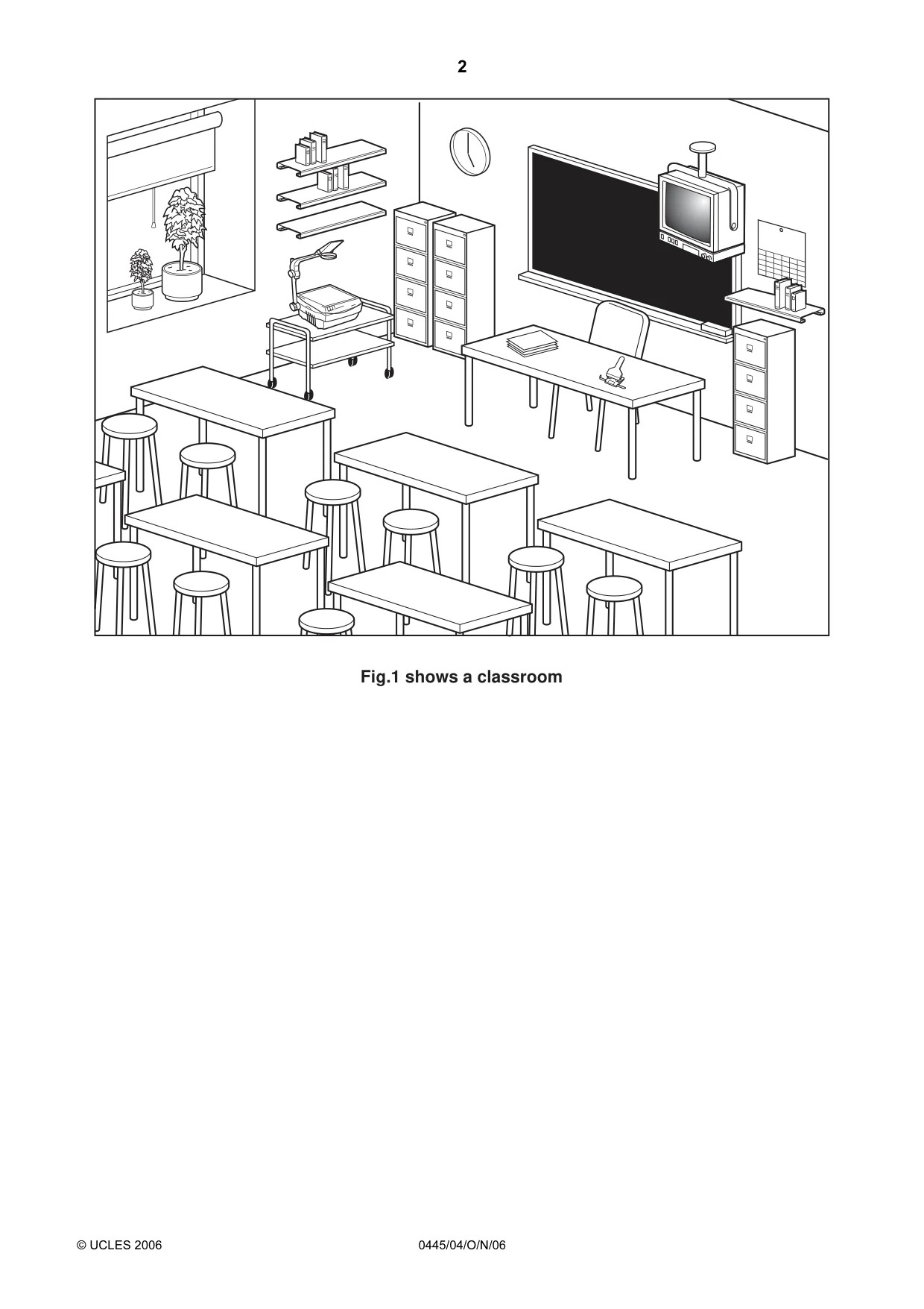
2 © UCLES 2006 0445/04/O/N/06 Fig.1 shows a classroom
Question paper, page 3
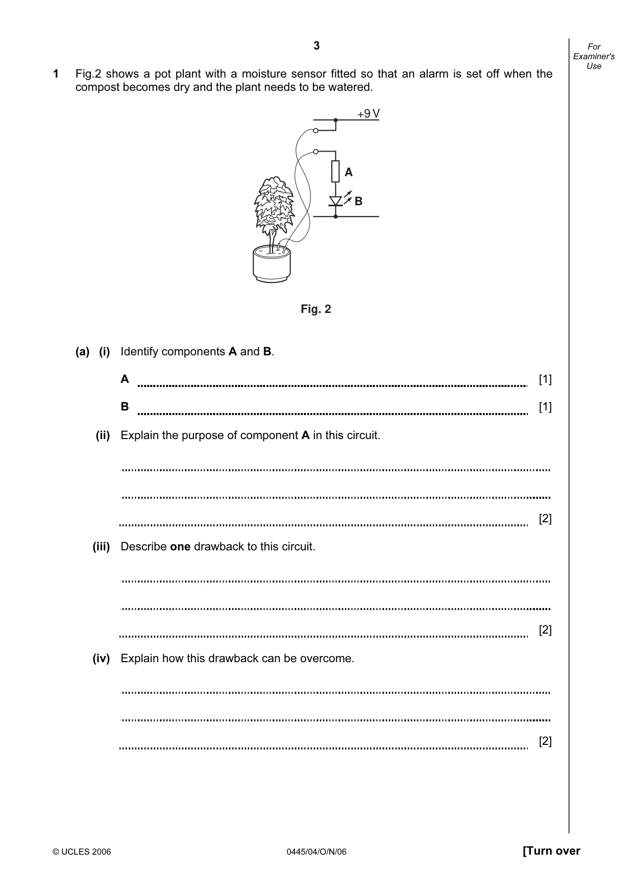
3 © UCLES 2006 0445/04/O/N/06 [Turn over For Examiner's Use 1 Fig.2 shows a pot plant with a moisture sensor fitted so that an alarm is set off when the compost becomes dry and the plant needs to be watered. Fig. 2 +9 V A B (a) (i) Identify components A and B. A [1] B [1] (ii) Explain the purpose of component A in this circuit. [2] (iii) Describe one drawback to this circuit. [2] (iv) Explain how this drawback can be overcome. [2]
Question paper, page 4
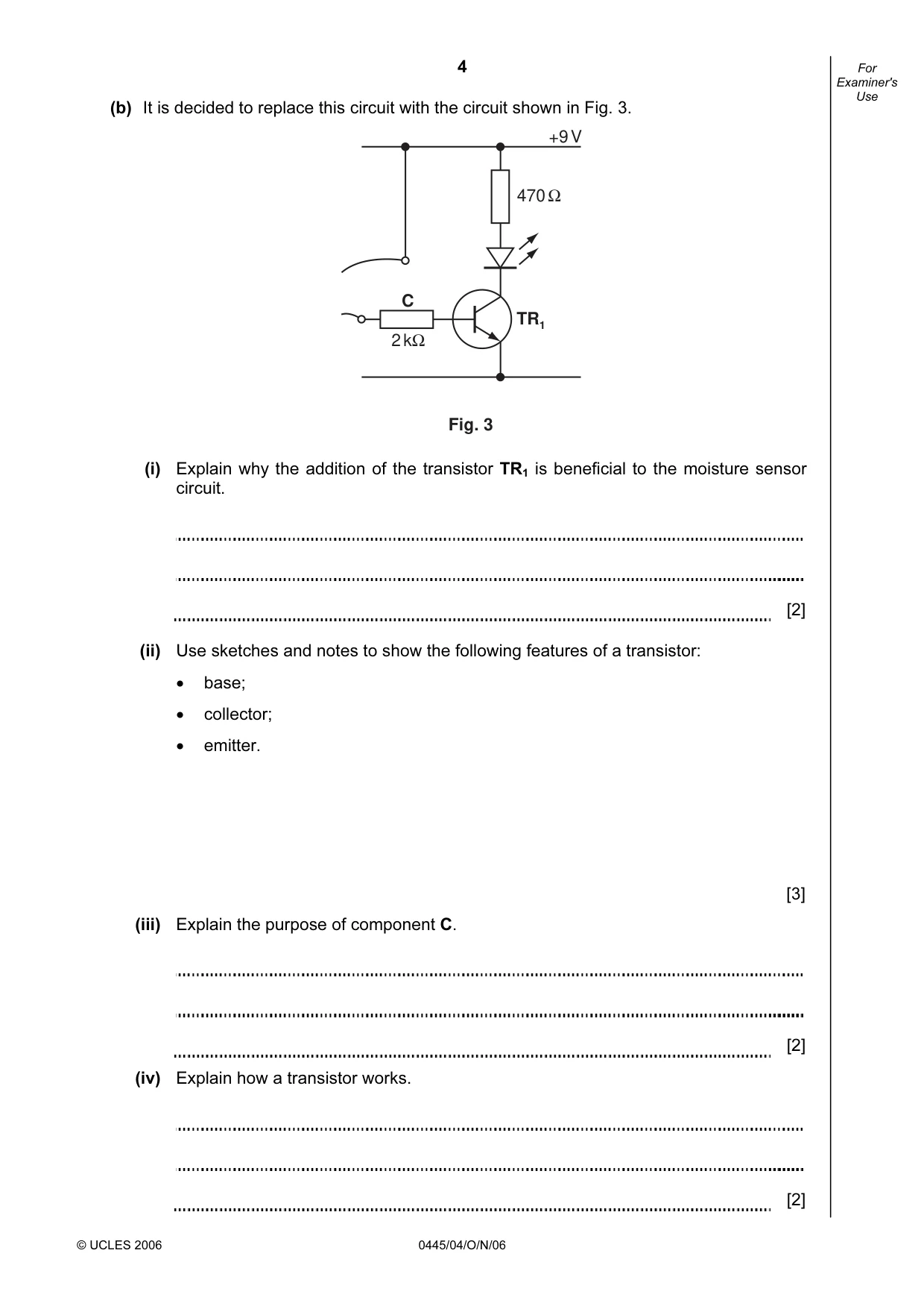
4 © UCLES 2006 0445/04/O/N/06 For Examiner's Use (b) It is decided to replace this circuit with the circuit shown in Fig. 3. TR1 C 470 Ω +9 V 2 kΩ Fig. 3 (i) Explain why the addition of the transistor TR1 is beneficial to the moisture sensor circuit. [2] (ii) Use sketches and notes to show the following features of a transistor: • base; • collector; • emitter. [3] (iii) Explain the purpose of component C. [2] (iv) Explain how a transistor works. [2]
Question paper, page 5
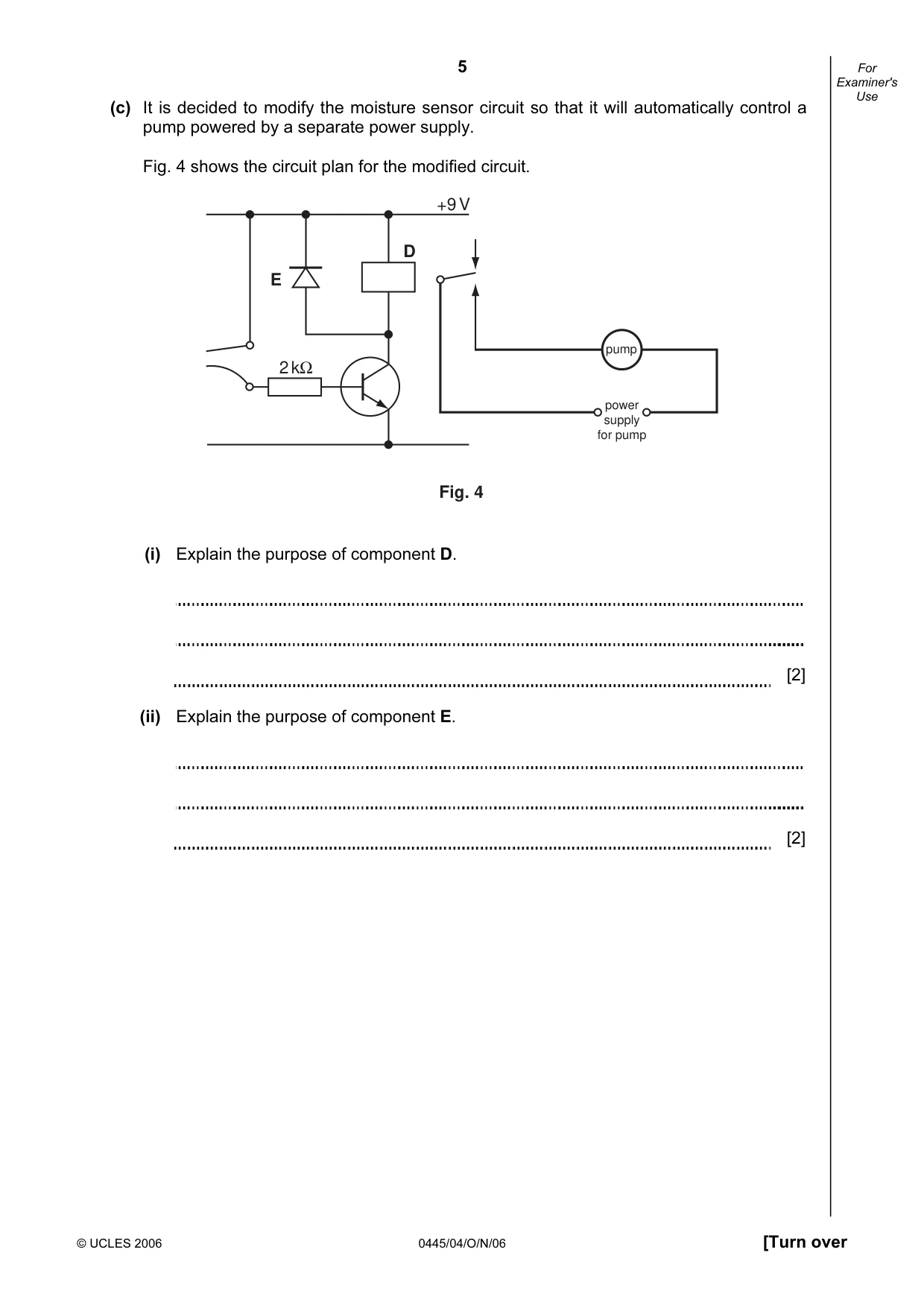
5 © UCLES 2006 0445/04/O/N/06 [Turn over For Examiner's Use (c) It is decided to modify the moisture sensor circuit so that it will automatically control a pump powered by a separate power supply. Fig. 4 shows the circuit plan for the modified circuit. +9 V 2 kΩ Fig. 4 D pump power supply for pump E (i) Explain the purpose of component D. [2] (ii) Explain the purpose of component E. [2]
Question paper, page 6
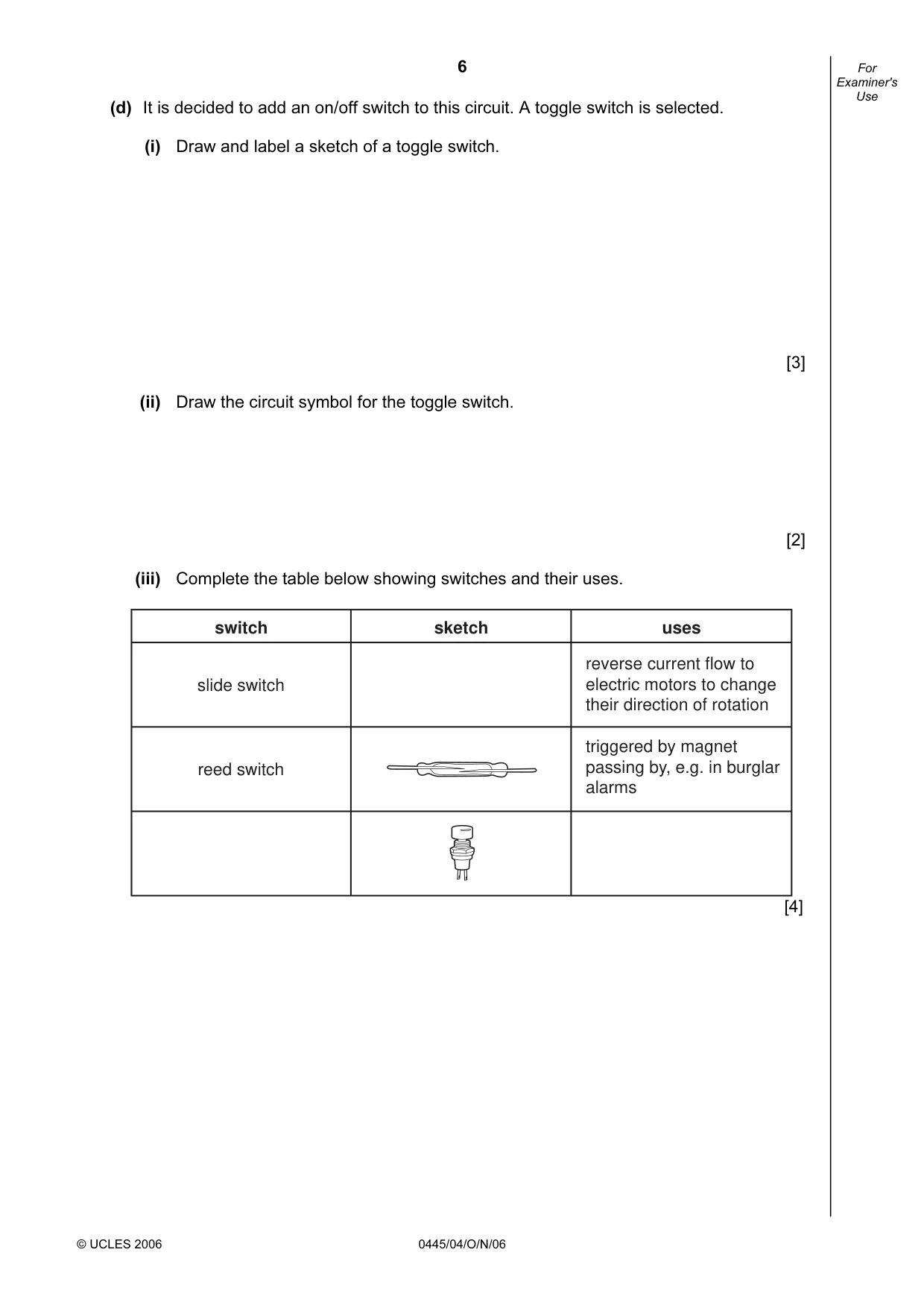
6 © UCLES 2006 0445/04/O/N/06 For Examiner's Use (d) It is decided to add an on/off switch to this circuit. A toggle switch is selected. (i) Draw and label a sketch of a toggle switch. [3] (ii) Draw the circuit symbol for the toggle switch. [2] (iii) Complete the table below showing switches and their uses. switch slide switch reed switch sketch uses reverse current flow to electric motors to change their direction of rotation triggered by magnet passing by, e.g. in burglar alarms [4]
Question paper, page 7
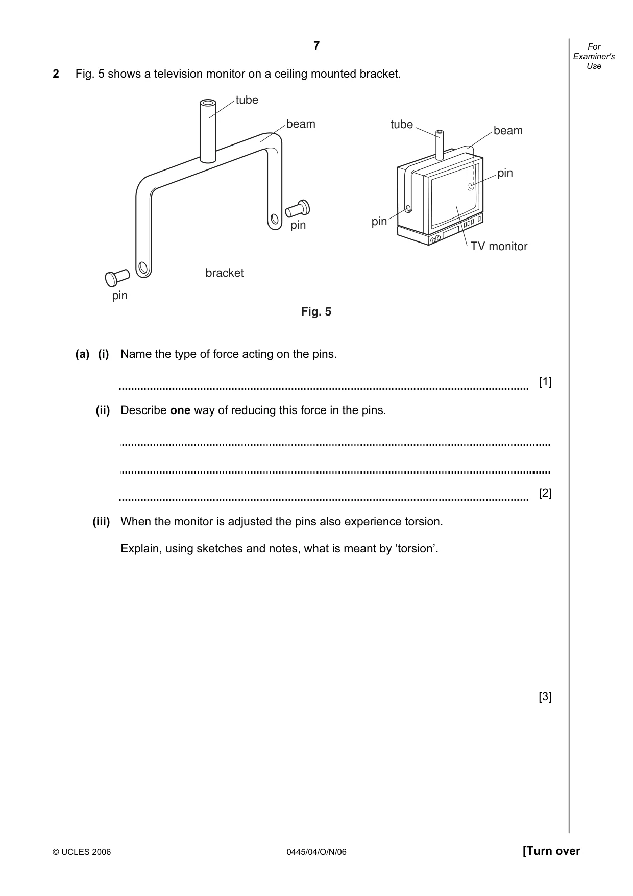
7 © UCLES 2006 0445/04/O/N/06 [Turn over For Examiner's Use 2 Fig. 5 shows a television monitor on a ceiling mounted bracket. Fig. 5 tube beam bracket pin pin pin pin tube beam TV monitor (a) (i) Name the type of force acting on the pins. [1] (ii) Describe one way of reducing this force in the pins. [2] (iii) When the monitor is adjusted the pins also experience torsion. Explain, using sketches and notes, what is meant by ‘torsion’. [3]
Question paper, page 8
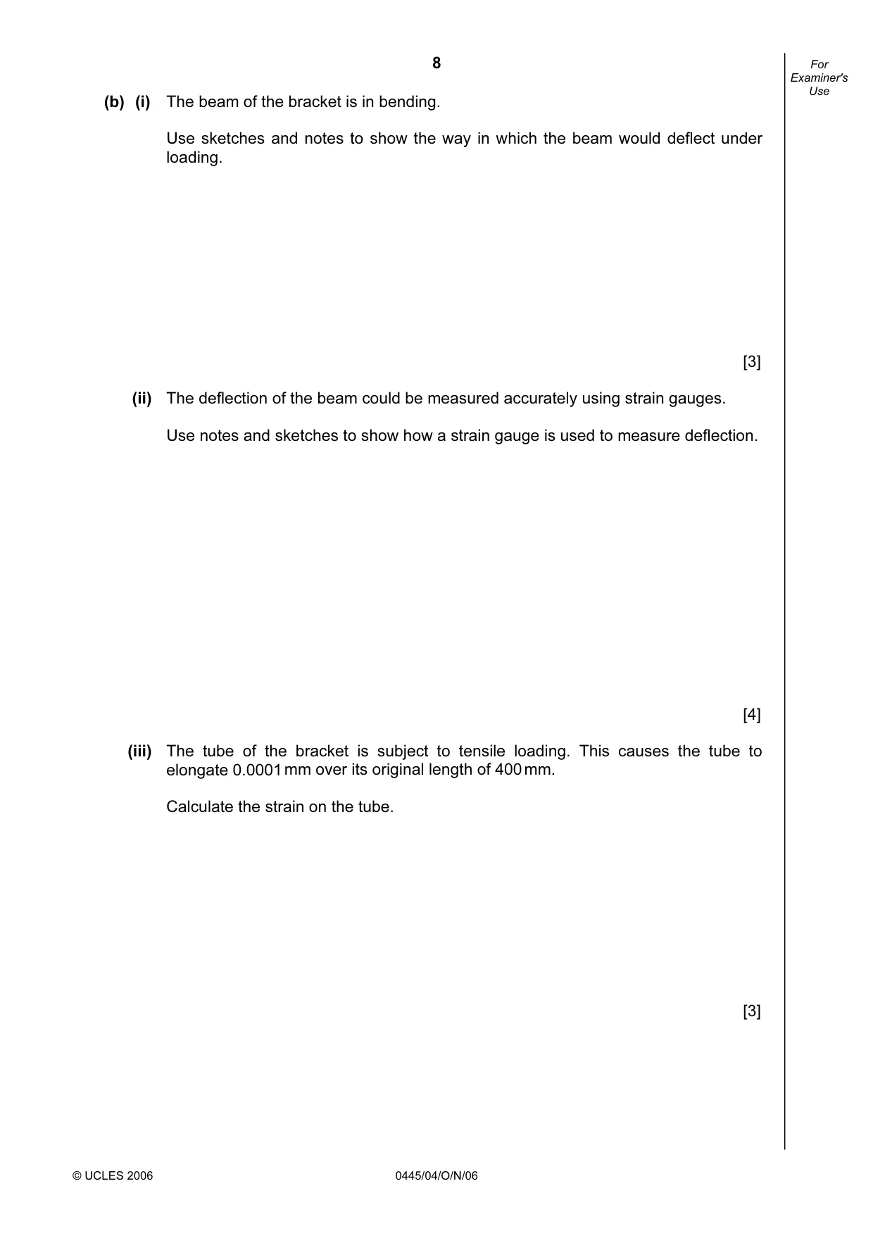
8 © UCLES 2006 0445/04/O/N/06 For Examiner's Use (b) (i) The beam of the bracket is in bending. Use sketches and notes to show the way in which the beam would deflect under loading. [3] (ii) The deflection of the beam could be measured accurately using strain gauges. Use notes and sketches to show how a strain gauge is used to measure deflection. [4] (iii) The tube of the bracket is subject to tensile loading. This causes the tube to elongate 0.0001 mm over its original length of 400 mm. Calculate the strain on the tube. [3]
Question paper, page 9
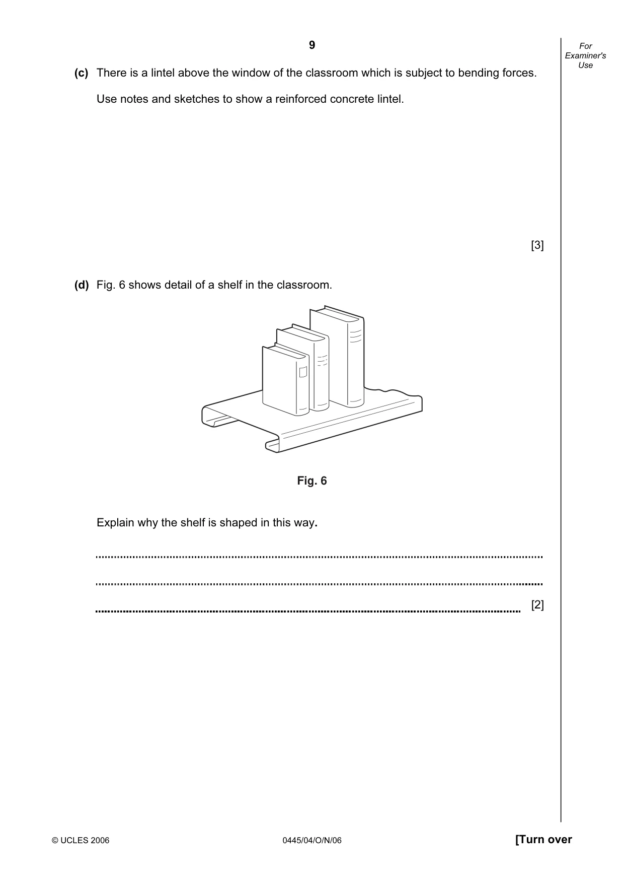
9 © UCLES 2006 0445/04/O/N/06 [Turn over For Examiner's Use (c) There is a lintel above the window of the classroom which is subject to bending forces. Use notes and sketches to show a reinforced concrete lintel. [3] (d) Fig. 6 shows detail of a shelf in the classroom. Fig. 6 Explain why the shelf is shaped in this way. [2]
Question paper, page 10
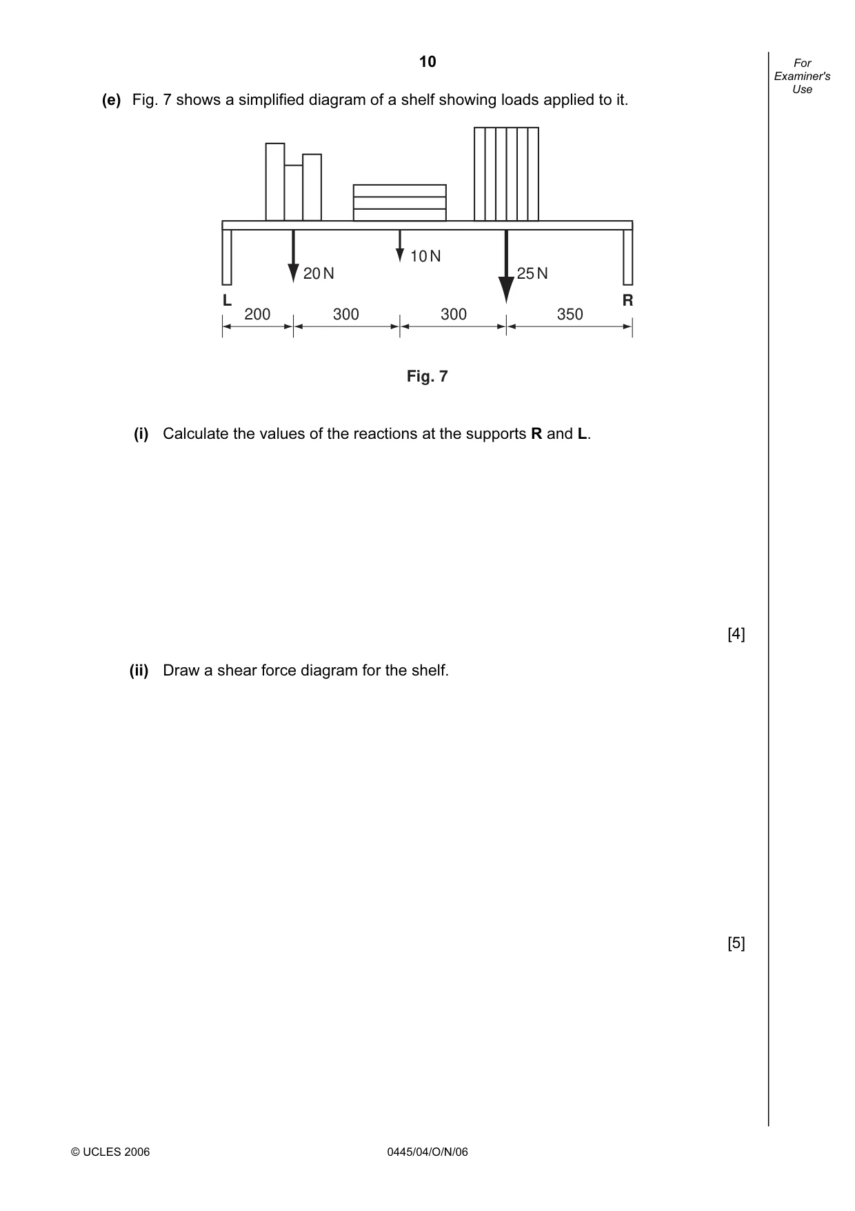
10 © UCLES 2006 0445/04/O/N/06 For Examiner's Use (e) Fig. 7 shows a simplified diagram of a shelf showing loads applied to it. L R 200 300 300 350 20 N 10 N 25 N Fig. 7 (i) Calculate the values of the reactions at the supports R and L. [4] (ii) Draw a shear force diagram for the shelf. [5]
Question paper, page 11
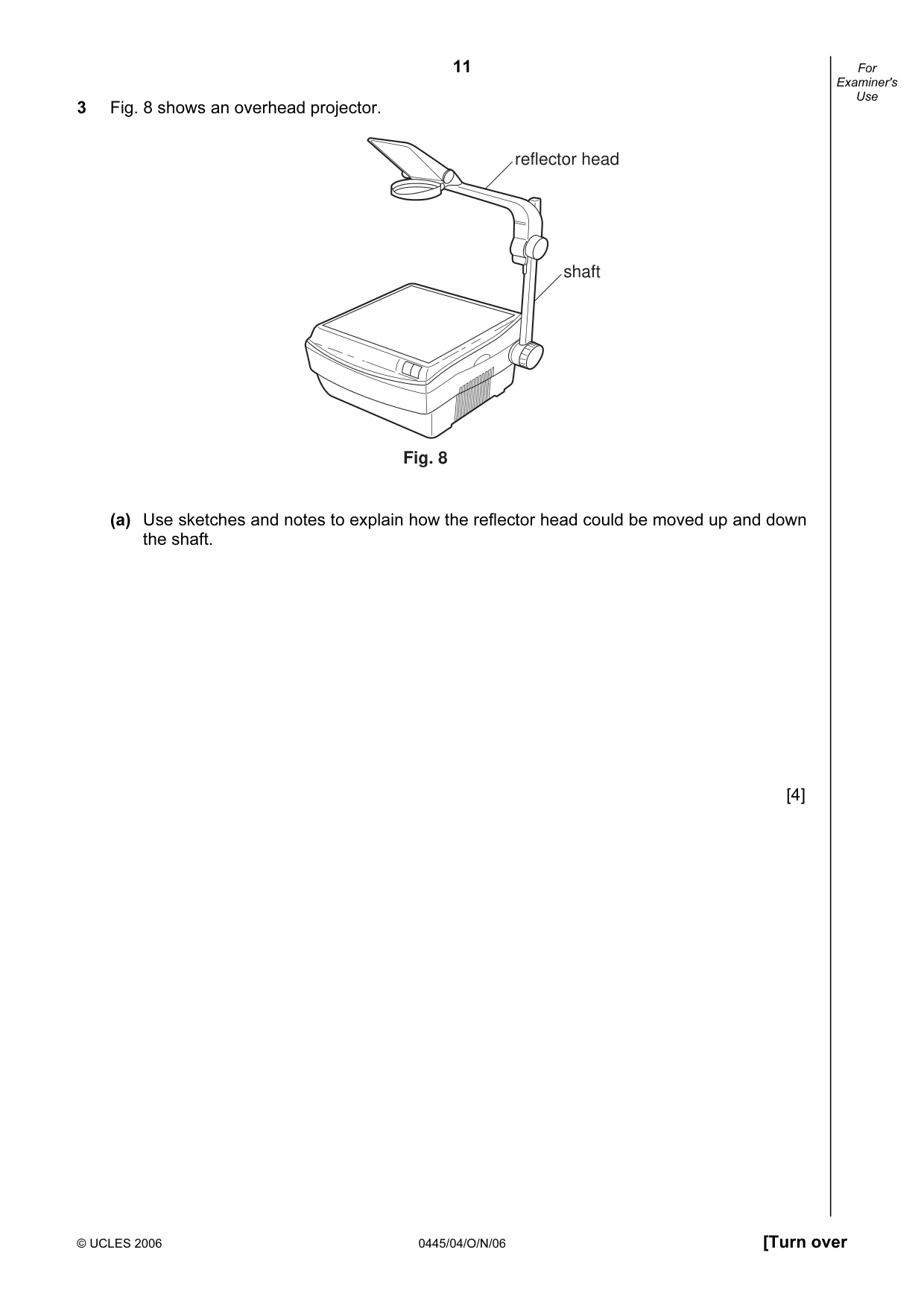
11 © UCLES 2006 0445/04/O/N/06 [Turn over For Examiner's Use 3 Fig. 8 shows an overhead projector. Fig. 8 reflector head shaft (a) Use sketches and notes to explain how the reflector head could be moved up and down the shaft. [4]
Question paper, page 12
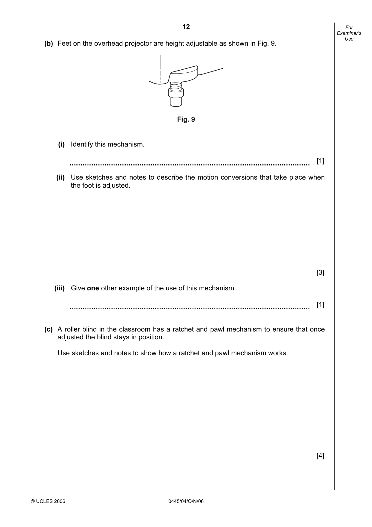
12 © UCLES 2006 0445/04/O/N/06 For Examiner's Use (b) Feet on the overhead projector are height adjustable as shown in Fig. 9. Fig. 9 (i) Identify this mechanism. [1] (ii) Use sketches and notes to describe the motion conversions that take place when the foot is adjusted. [3] (iii) Give one other example of the use of this mechanism. [1] (c) A roller blind in the classroom has a ratchet and pawl mechanism to ensure that once adjusted the blind stays in position. Use sketches and notes to show how a ratchet and pawl mechanism works. [4]
Question paper, page 13
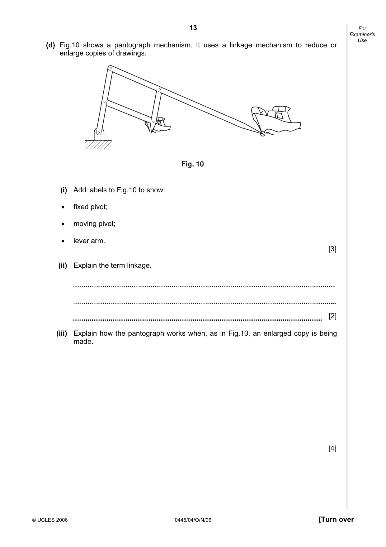
13 © UCLES 2006 0445/04/O/N/06 [Turn over For Examiner's Use (d) Fig.10 shows a pantograph mechanism. It uses a linkage mechanism to reduce or enlarge copies of drawings. Fig. 10 (i) Add labels to Fig.10 to show: • fixed pivot; • moving pivot; • lever arm. [3] (ii) Explain the term linkage. [2] (iii) Explain how the pantograph works when, as in Fig.10, an enlarged copy is being made. [4]
Question paper, page 14
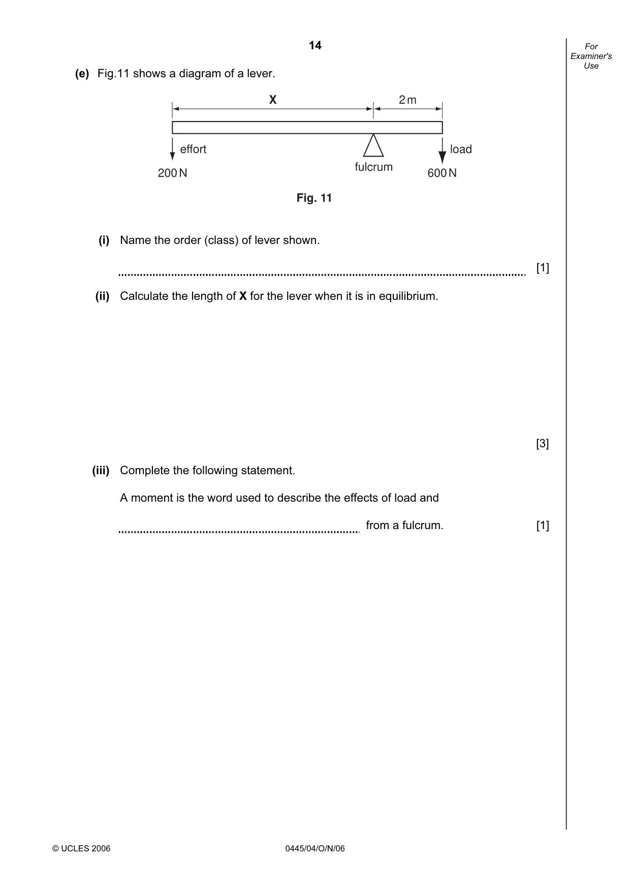
14 © UCLES 2006 0445/04/O/N/06 For Examiner's Use (e) Fig.11 shows a diagram of a lever. fulcrum X 2 m 600 N 200 N effort load Fig. 11 (i) Name the order (class) of lever shown. [1] (ii) Calculate the length of X for the lever when it is in equilibrium. [3] (iii) Complete the following statement. A moment is the word used to describe the effects of load and from a fulcrum. [1]
Question paper, page 15
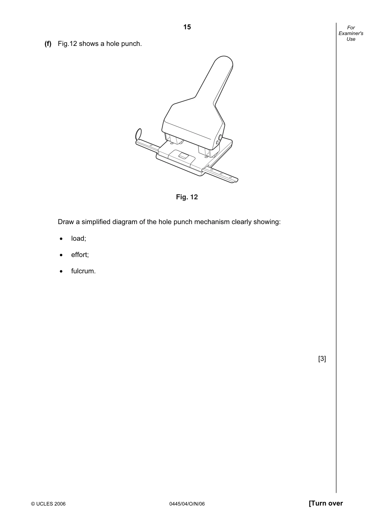
15 © UCLES 2006 0445/04/O/N/06 [Turn over For Examiner's Use (f) Fig.12 shows a hole punch. Fig. 12 Draw a simplified diagram of the hole punch mechanism clearly showing: • load; • effort; • fulcrum. [3]
Question paper, page 16
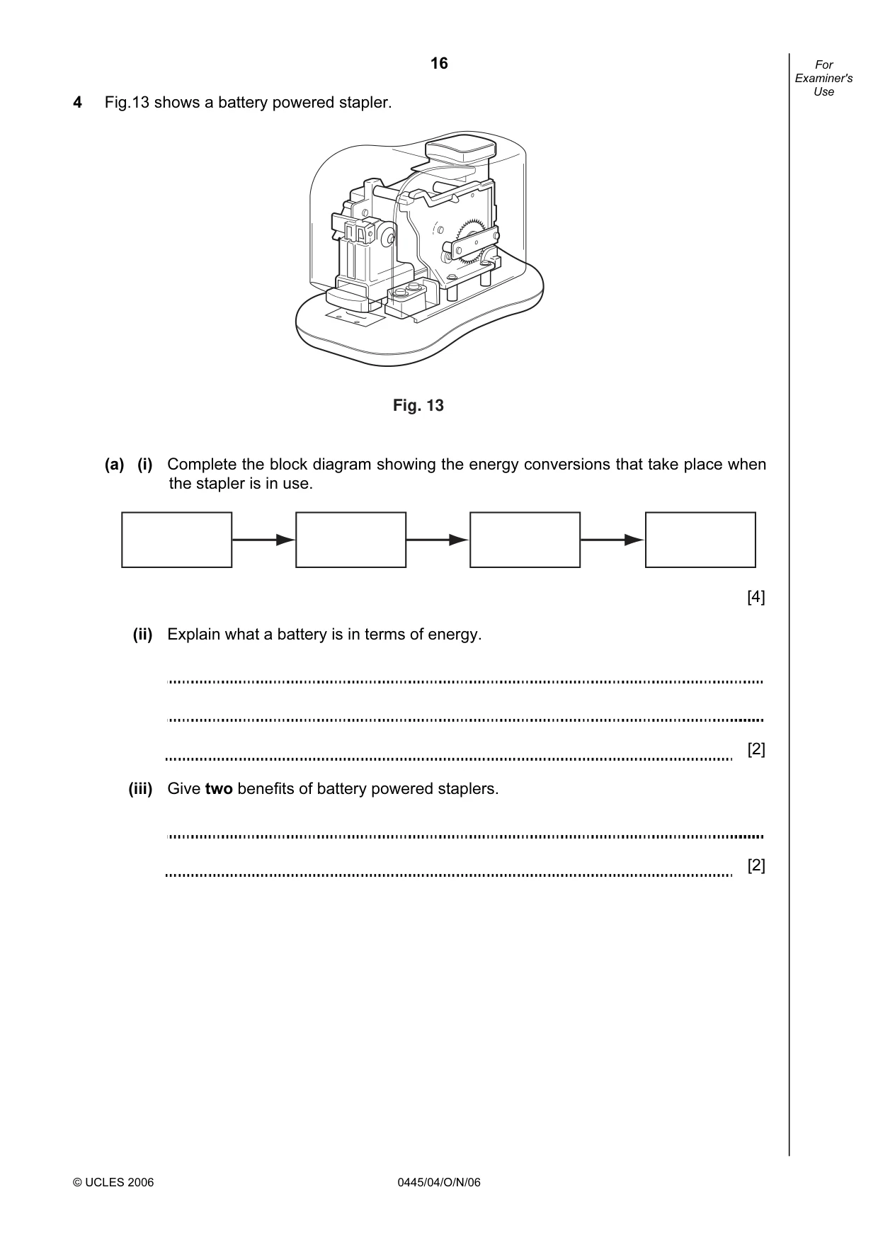
16 © UCLES 2006 0445/04/O/N/06 For Examiner's Use 4 Fig.13 shows a battery powered stapler. Fig. 13 (a) (i) Complete the block diagram showing the energy conversions that take place when the stapler is in use. [4] (ii) Explain what a battery is in terms of energy. [2] (iii) Give two benefits of battery powered staplers. [2]
Question paper, page 17
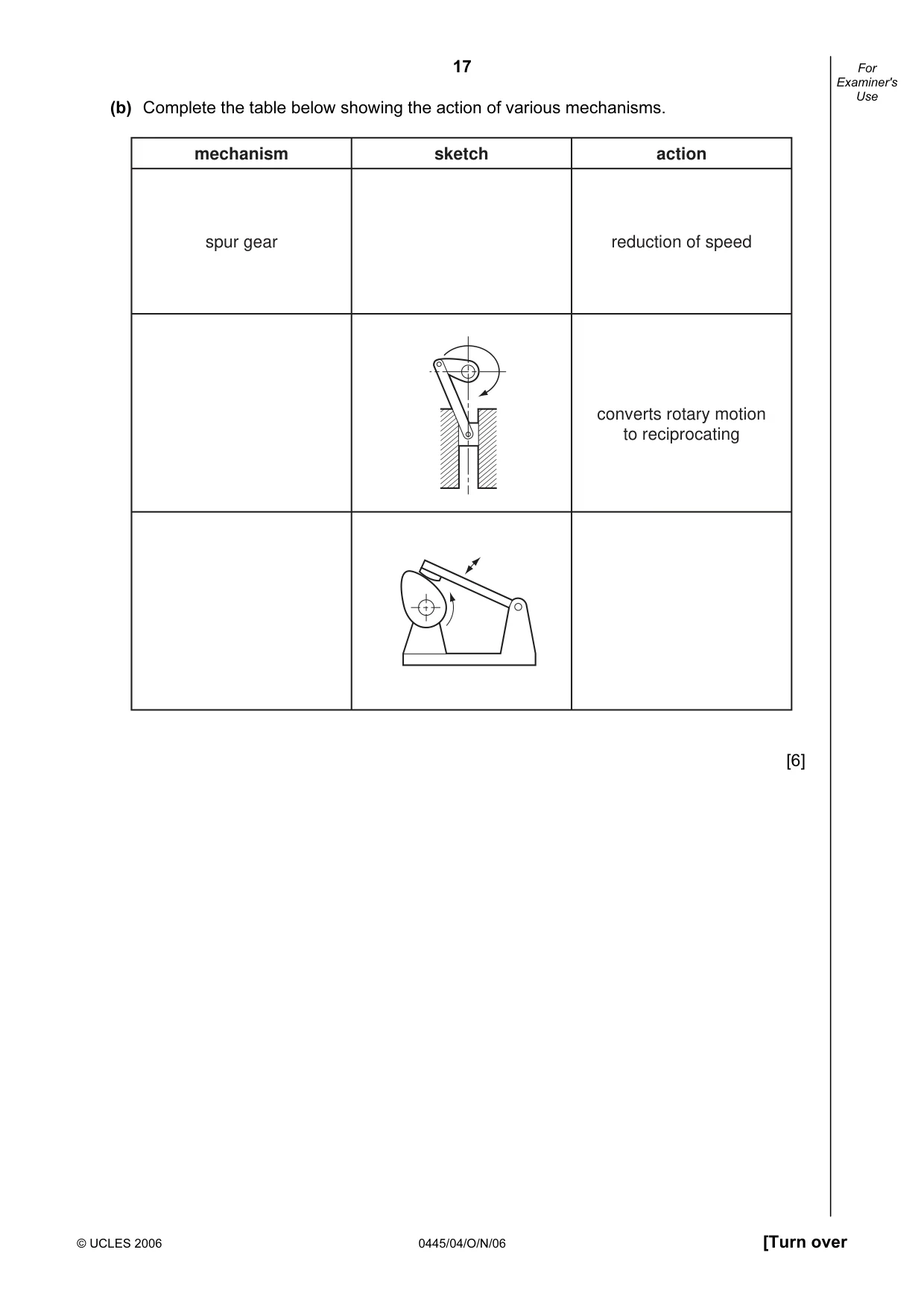
17 © UCLES 2006 0445/04/O/N/06 [Turn over For Examiner's Use (b) Complete the table below showing the action of various mechanisms. mechanism spur gear reduction of speed converts rotary motion to reciprocating sketch action [6]
Question paper, page 18
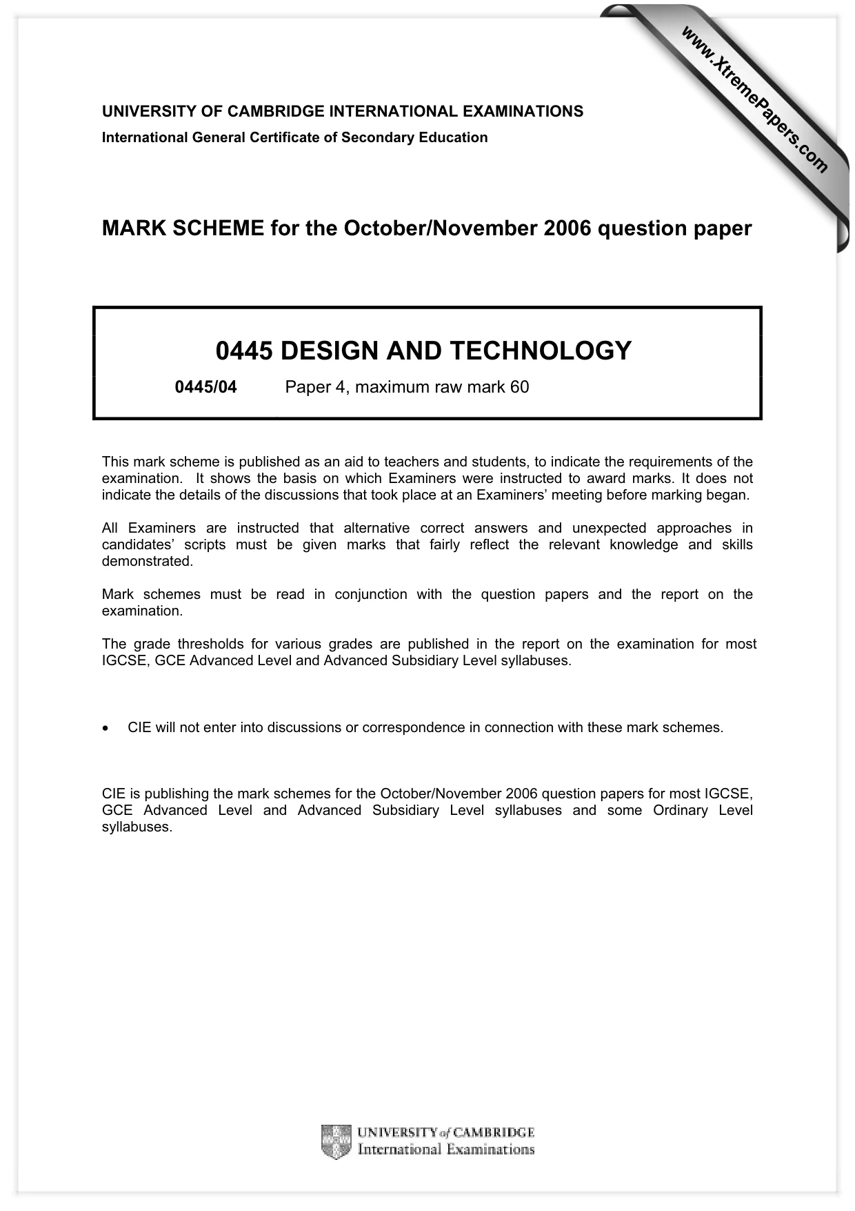
18 © UCLES 2006 0445/04/O/N/06 For Examiner's Use (c) Fig. 14 shows a hand powered stapler. A sectional view spring Fig. 14 (i) Explain in terms of energy how the spring provides the power for the stapler. [3] (ii) Add labels to view A to show how the handle acts as a lever. Show clearly: • effort; • load; • fulcrum. [3] (iii) A student is asked to make a demonstration model of the stapler lever mechanism. Use sketches and notes to show one method of modelling the stapler lever mechanism. [4]
Question paper, page 19
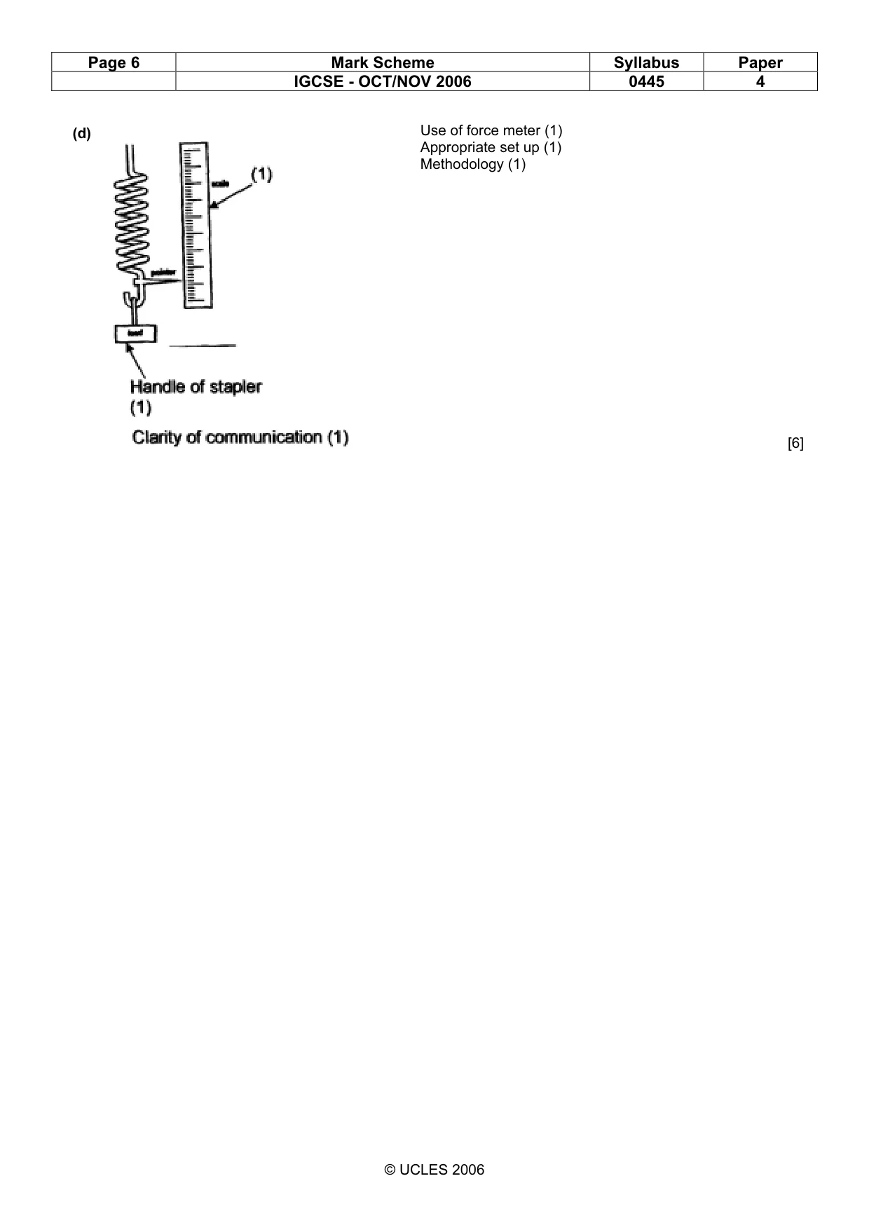
19 © UCLES 2006 0445/04/O/N/06 For Examiner's Use (d) A test rig is required to determine the force needed to staple various thicknesses of paper using the hand stapler. Use notes and sketches to show a design for such a test rig. Show clearly how the force would be measured. [6]
Question paper, page 20
20 Permission to reproduce items where third-party owned material protected by copyright is included has been sought and cleared where possible. Every reasonable effort has been made by the publisher (UCLES) to trace copyright holders, but if any items requiring clearance have unwittingly been included, the publisher will be pleased to make amends at the earliest possible opportunity. University of Cambridge International Examinations is part of the University of Cambridge Local Examinations Syndicate (UCLES), which is itself a department of the University of Cambridge. 0445/04/O/N/06 BLANK PAGE
Mark scheme, page 1
UNIVERSITY OF CAMBRIDGE INTERNATIONAL EXAMINATIONS International General Certificate of Secondary Education MARK SCHEME for the October/November 2006 question paper 0445 DESIGN AND TECHNOLOGY 0445/04 Paper 4, maximum raw mark 60 This mark scheme is published as an aid to teachers and students, to indicate the requirements of the examination. It shows the basis on which Examiners were instructed to award marks. It does not indicate the details of the discussions that took place at an Examiners’ meeting before marking began. All Examiners are instructed that alternative correct answers and unexpected approaches in candidates’ scripts must be given marks that fairly reflect the relevant knowledge and skills demonstrated. Mark schemes must be read in conjunction with the question papers and the report on the examination. The grade thresholds for various grades are published in the report on the examination for most IGCSE, GCE Advanced Level and Advanced Subsidiary Level syllabuses. • CIE will not enter into discussions or correspondence in connection with these mark schemes. CIE is publishing the mark schemes for the October/November 2006 question papers for most IGCSE, GCE Advanced Level and Advanced Subsidiary Level syllabuses and some Ordinary Level syllabuses. www.XtremePapers.com
Mark scheme, page 2
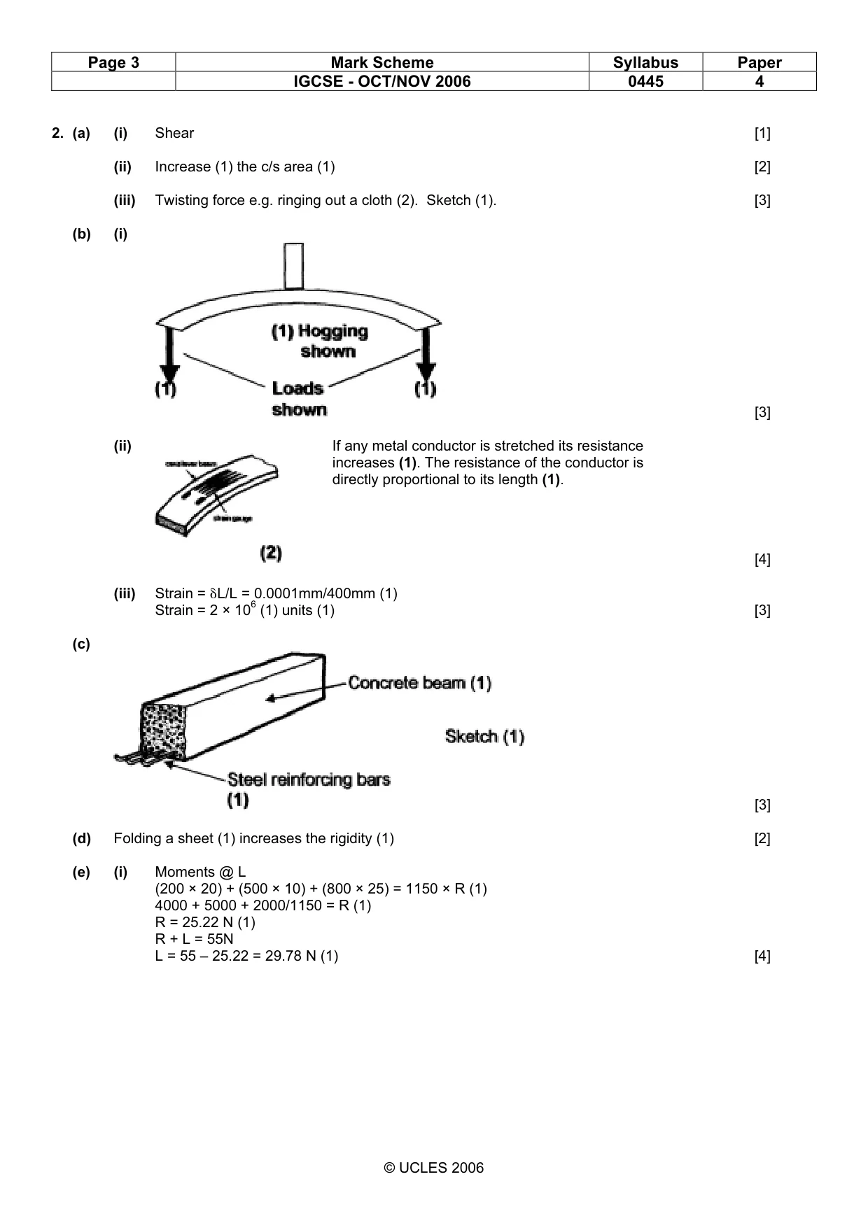
Page 2 Mark Scheme Syllabus Paper IGCSE - OCT/NOV 2006 0445 4 © UCLES 2006 1. (a) (i) A. Resistor [1] B. Light emitting diode (LED) [1] (ii) To control value of voltage across the LED (1) and so protect it from overload (1) [2] (iii) It is always ‘on’ (1). It is not sensitive enough (2) [2] (iv) Add a switch (1) between battery and probe (1) or add a variable resistor or transistor into circuit (2) [2] (b) (i) Makes the circuit quicker to react (1) to the presence of smaller amount of moisture (1) or increase sensitivity (2) [2] (ii) Base (1), Collector (1), Emitter (1) [3] (iii) Sets the trigger (bias) voltage of the transistor (1) so controls the switch on point of the transistor (1) [2] (iv) A small current through the Base circuit (1) controls the flow of a larger current through the collector/emitter circuit (1). Thus a small change can be amplified (1) [2] (c) (i) Interfaces (1) between low voltage circuit and higher voltage circuit (1). [2] (ii) Protects the transistor (1) from back EMF (1). [2] (d) (i) [3] (ii) [2] (iii) [4] Switch Sketch Uses Slide switch [2] Reverse current flow to electric motors to change their direction of rotation. Reed switch Triggered by magnet passing by, e.g. in burglar alarms. Push switch [1] Switching on momentarily. [1]
Mark scheme, page 3
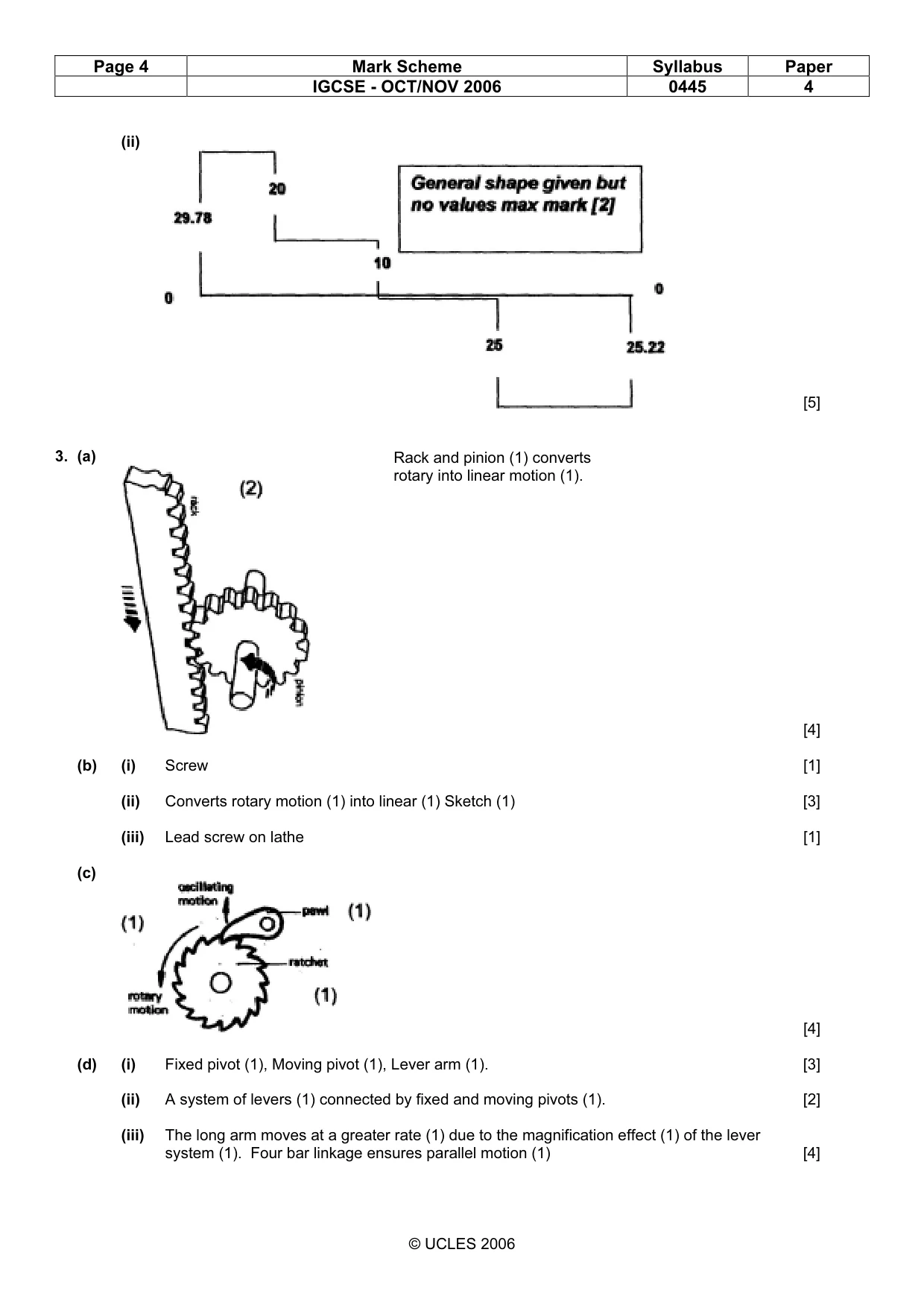
Page 3 Mark Scheme Syllabus Paper IGCSE - OCT/NOV 2006 0445 4 © UCLES 2006 2. (a) (i) Shear [1] (ii) Increase (1) the c/s area (1) [2] (iii) Twisting force e.g. ringing out a cloth (2). Sketch (1). [3] (b) (i) [3] (ii) [4] (iii) Strain = ÇL/L = 0.0001mm/400mm (1) Strain = 2 × 10⁶ (1) units (1) [3] (c) [3] (d) Folding a sheet (1) increases the rigidity (1) [2] (e) (i) Moments @ L (200 × 20) + (500 × 10) + (800 × 25) = 1150 × R (1) 4000 + 5000 + 2000/1150 = R (1) R = 25.22 N (1) R + L = 55N L = 55 – 25.22 = 29.78 N (1) [4] If any metal conductor is stretched its resistance increases (1). The resistance of the conductor is directly proportional to its length (1).
Mark scheme, page 4
Page 4 Mark Scheme Syllabus Paper IGCSE - OCT/NOV 2006 0445 4 © UCLES 2006 (ii) [5] 3. (a) [4] (b) (i) Screw [1] (ii) Converts rotary motion (1) into linear (1) Sketch (1) [3] (iii) Lead screw on lathe [1] (c) [4] (d) (i) Fixed pivot (1), Moving pivot (1), Lever arm (1). [3] (ii) A system of levers (1) connected by fixed and moving pivots (1). [2] (iii) The long arm moves at a greater rate (1) due to the magnification effect (1) of the lever system (1). Four bar linkage ensures parallel motion (1) [4] Rack and pinion (1) converts rotary into linear motion (1).
Mark scheme, page 5
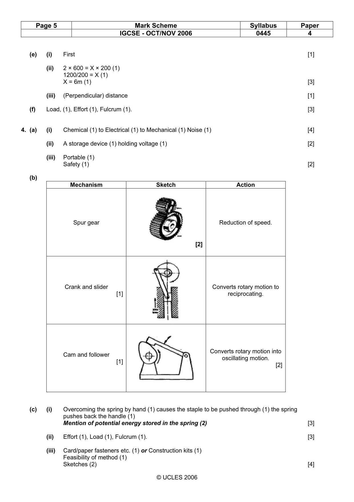
Page 5 Mark Scheme Syllabus Paper IGCSE - OCT/NOV 2006 0445 4 © UCLES 2006 (e) (i) First [1] (ii) 2 × 600 = X × 200 (1) 1200/200 = X (1) X = 6m (1) [3] (iii) (Perpendicular) distance [1] (f) Load, (1), Effort (1), Fulcrum (1). [3] 4. (a) (i) Chemical (1) to Electrical (1) to Mechanical (1) Noise (1) [4] (ii) A storage device (1) holding voltage (1) [2] (iii) Portable (1) Safety (1) [2] (b) Mechanism Sketch Action Spur gear [2] Reduction of speed. Crank and slider [1] Converts rotary motion to reciprocating. Cam and follower [1] Converts rotary motion into oscillating motion. [2] (c) (i) Overcoming the spring by hand (1) causes the staple to be pushed through (1) the spring pushes back the handle (1) Mention of potential energy stored in the spring (2) [3] (ii) Effort (1), Load (1), Fulcrum (1). [3] (iii) Card/paper fasteners etc. (1) or Construction kits (1) Feasibility of method (1) Sketches (2) [4]
Mark scheme, page 6
Page 6 Mark Scheme Syllabus Paper IGCSE - OCT/NOV 2006 0445 4 © UCLES 2006 (d) [6] Use of force meter (1) Appropriate set up (1) Methodology (1)