Cambridge IGCSE Design and Technology 0445 — 2006 May/June Paper 4 · Variant 1
0445/41/M/J/06 · 100 marks · ≈113 min
The question paper and its mark scheme, free to read here and free to download. This is Cambridge’s own paper, exactly as it was sat.
Question paper16 pages
Mark scheme7 pages
Answers below. Sit the paper first if you are practising.
Paper as text
Question paper, page 1
Centre Number Candidate Number Name UNIVERSITY OF CAMBRIDGE INTERNATIONAL EXAMINATIONS International General Certificate of Secondary Education DESIGN AND TECHNOLOGY 0445/04 Paper 4 Technology May/June 2006 1 hour Candidates answer on the Question Paper. No Additional Materials are required. To be taken together with Paper 1 in one session of 2 hours 45 minutes. READ THESE INSTRUCTIONS FIRST Write your Centre number, candidate number and name on all the work you hand in. Write in dark blue or black pen in the spaces provided on the Question Paper. You may use a soft pencil for any diagrams, graphs or rough working. Do not use staples, paper clips, highlighters, glue or correction fluid. Answer any two questions. You may use a calculator. At the end of the examination, fasten all your work securely together. The number of marks is given in brackets [ ] at the end of each question or part question. FOR EXAMINER’S USE 1 2 3 4 TOTAL This document consists of 16 printed pages. IB06 06_0445_04/2RP UCLES 2006 [Turn over www.XtremePapers.com
Question paper, page 2
2 © UCLES 2006 0445/04/M/J/06 For Examiner's Use 1 Fig. 1 shows a student’s design for an electronic game. hoop wire loop Fig. 1 (a) Draw a simple circuit using a battery and buzzer that would make a sound when the hoop touches the wire loop. [4] (b) After testing the simple circuit it is decided to use a 555 timer circuit as shown in Fig. 2. + + 9 V 10 kΩ 10 kΩ A 555 0.1 µF 1 µF 0.1 µF C speaker 80 Ω Fig. 2
Question paper, page 3
3 © UCLES 2006 0445/04/M/J/06 [Turn over For Examiner's Use (i) Explain two benefits of using the 555 circuit. [4] (ii) Explain the purpose of component A. [3] (iii) Label the 555 IC in Fig. 2 to show the pin numbers. [3] (iv) Name the type of capacitor shown as C. [1] (c) For the circuit shown in Fig. 2 complete the block diagram below. INPUT TIMER CONTROL OUTPUT Name Symbol Sketch Slide switch 555 IC 555 555 [5]
Question paper, page 4
4 © UCLES 2006 0445/04/M/J/06 For Examiner's Use (d) Fig. 3 shows a chart for selecting values of resistance and capacitance for a time delay circuit. resistor (ohms) time required (seconds) capacitor (microfarads) 1kΩ 10kΩ 100kΩ 1MΩ 10MΩ 0.1µF 1µF 10µF 100µF 1000µF 10µs 100µs 1ms 100ms 10s 1000s 100ms 1s 100s example Fig. 3 (i) State the values of resistance (R) and capacitance (C) for the example time delay of 10 seconds. R C [2] (ii) Use the chart to find the time delay created by combining a resistance of 10 MΩ with a capacitance of 100 µF. [1] (iii) You could calculate the value of a time delay using a standard formula. State the formula used for calculating a time delay. [2]
Question paper, page 5
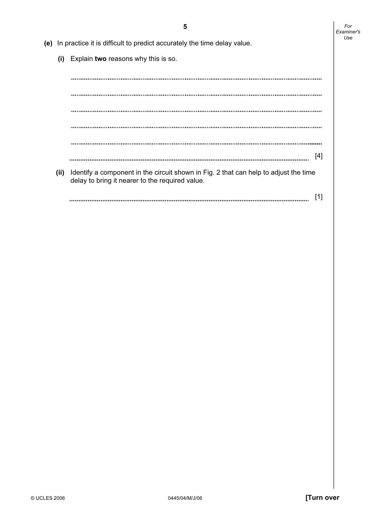
5 © UCLES 2006 0445/04/M/J/06 [Turn over For Examiner's Use (e) In practice it is difficult to predict accurately the time delay value. (i) Explain two reasons why this is so. [4] (ii) Identify a component in the circuit shown in Fig. 2 that can help to adjust the time delay to bring it nearer to the required value. [1]
Question paper, page 6
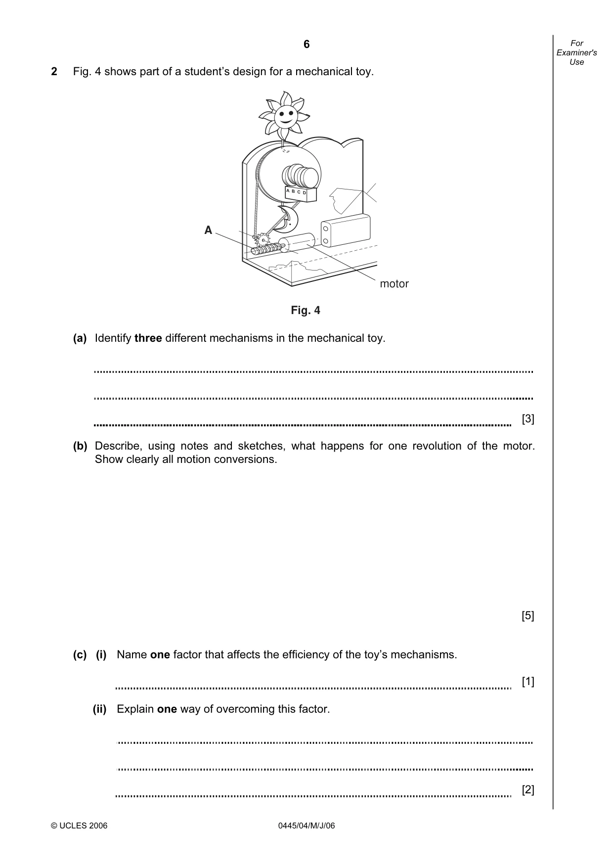
6 © UCLES 2006 0445/04/M/J/06 For Examiner's Use 2 Fig. 4 shows part of a student’s design for a mechanical toy. Fig. 4 A motor (a) Identify three different mechanisms in the mechanical toy. [3] (b) Describe, using notes and sketches, what happens for one revolution of the motor. Show clearly all motion conversions. [5] (c) (i) Name one factor that affects the efficiency of the toy’s mechanisms. [1] (ii) Explain one way of overcoming this factor. [2]
Question paper, page 7
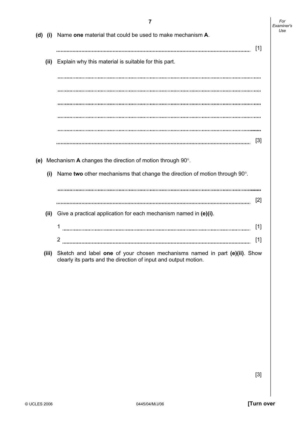
7 © UCLES 2006 0445/04/M/J/06 [Turn over For Examiner's Use (d) (i) Name one material that could be used to make mechanism A. [1] (ii) Explain why this material is suitable for this part. [3] (e) Mechanism A changes the direction of motion through 90°. (i) Name two other mechanisms that change the direction of motion through 90°. [2] (ii) Give a practical application for each mechanism named in (e)(i). 1 [1] 2 [1] (iii) Sketch and label one of your chosen mechanisms named in part (e)(ii). Show clearly its parts and the direction of input and output motion. [3]
Question paper, page 8
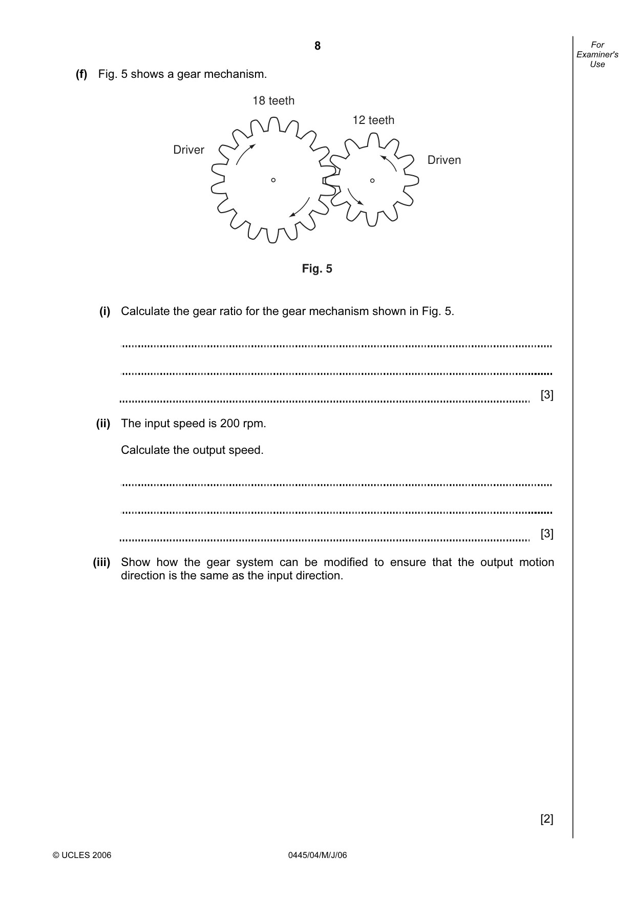
8 © UCLES 2006 0445/04/M/J/06 For Examiner's Use (f) Fig. 5 shows a gear mechanism. Driver 18 teeth 12 teeth Driven Fig. 5 (i) Calculate the gear ratio for the gear mechanism shown in Fig. 5. [3] (ii) The input speed is 200 rpm. Calculate the output speed. [3] (iii) Show how the gear system can be modified to ensure that the output motion direction is the same as the input direction. [2]
Question paper, page 9
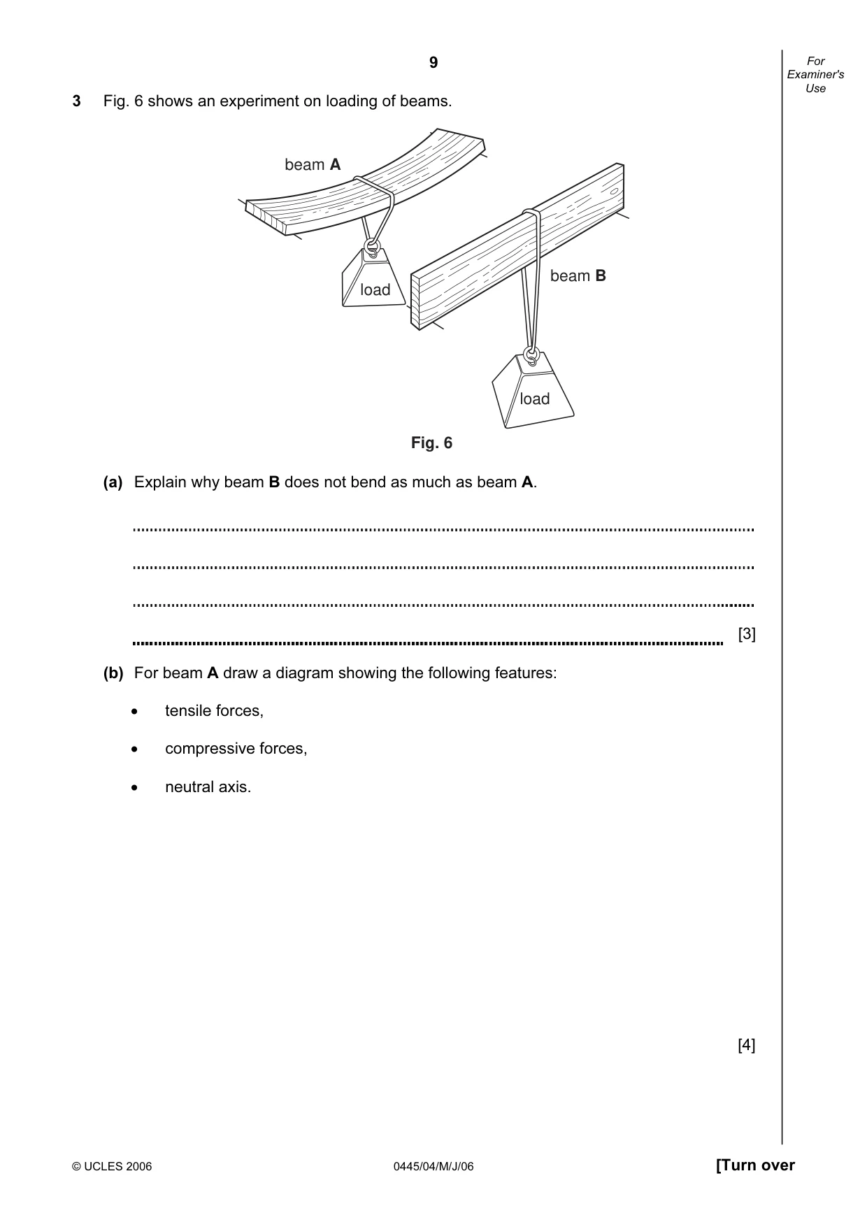
9 © UCLES 2006 0445/04/M/J/06 [Turn over For Examiner's Use 3 Fig. 6 shows an experiment on loading of beams. beam A beam B load load Fig. 6 (a) Explain why beam B does not bend as much as beam A. [3] (b) For beam A draw a diagram showing the following features: • tensile forces, • compressive forces, • neutral axis. [4]
Question paper, page 10
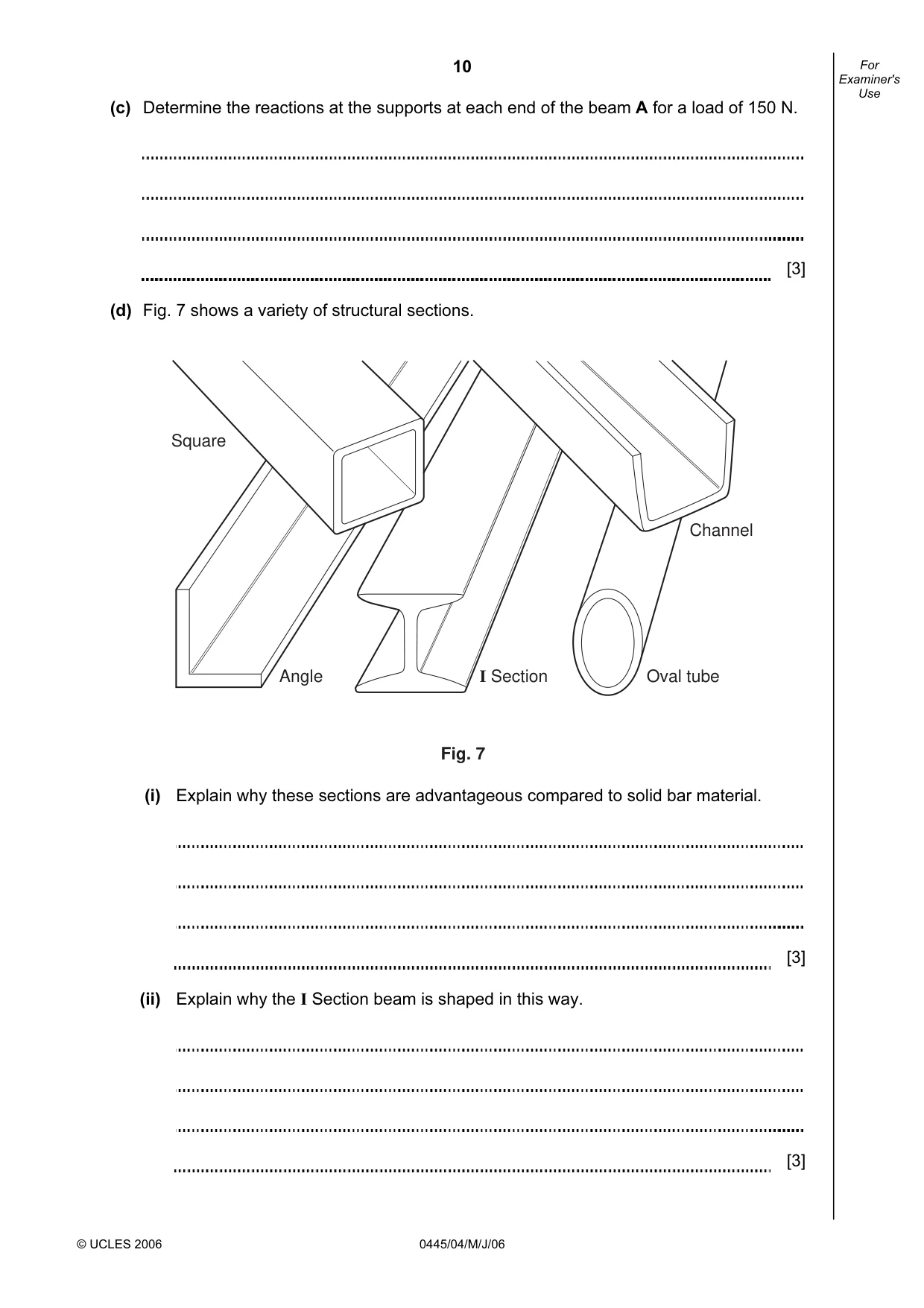
10 © UCLES 2006 0445/04/M/J/06 For Examiner's Use (c) Determine the reactions at the supports at each end of the beam A for a load of 150 N. [3] (d) Fig. 7 shows a variety of structural sections. Square Angle I Section Oval tube Channel Fig. 7 (i) Explain why these sections are advantageous compared to solid bar material. [3] (ii) Explain why the I Section beam is shaped in this way. [3]
Question paper, page 11
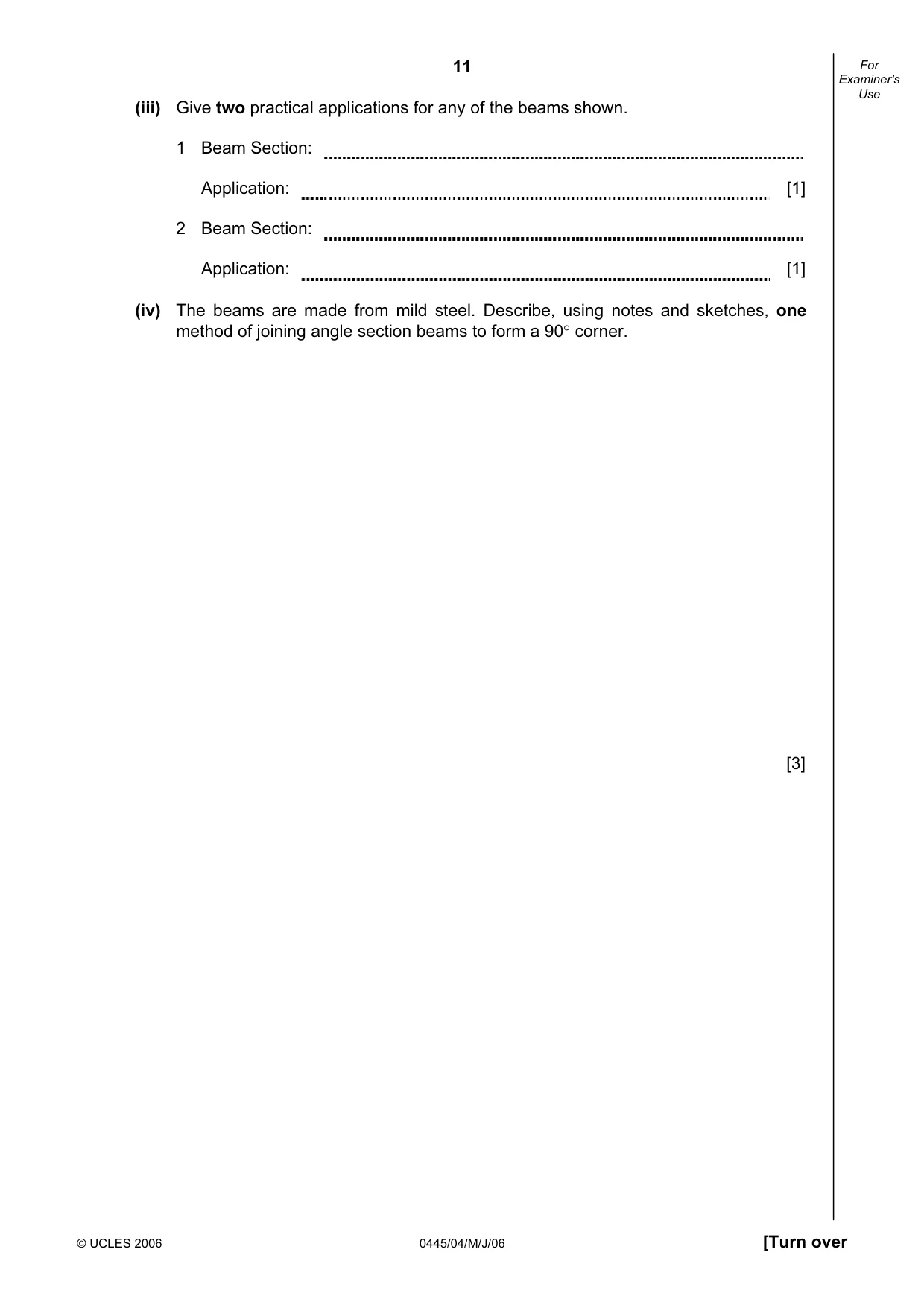
11 © UCLES 2006 0445/04/M/J/06 [Turn over For Examiner's Use (iii) Give two practical applications for any of the beams shown. 1 Beam Section: Application: [1] 2 Beam Section: Application: [1] (iv) The beams are made from mild steel. Describe, using notes and sketches, one method of joining angle section beams to form a 90° corner. [3]
Question paper, page 12
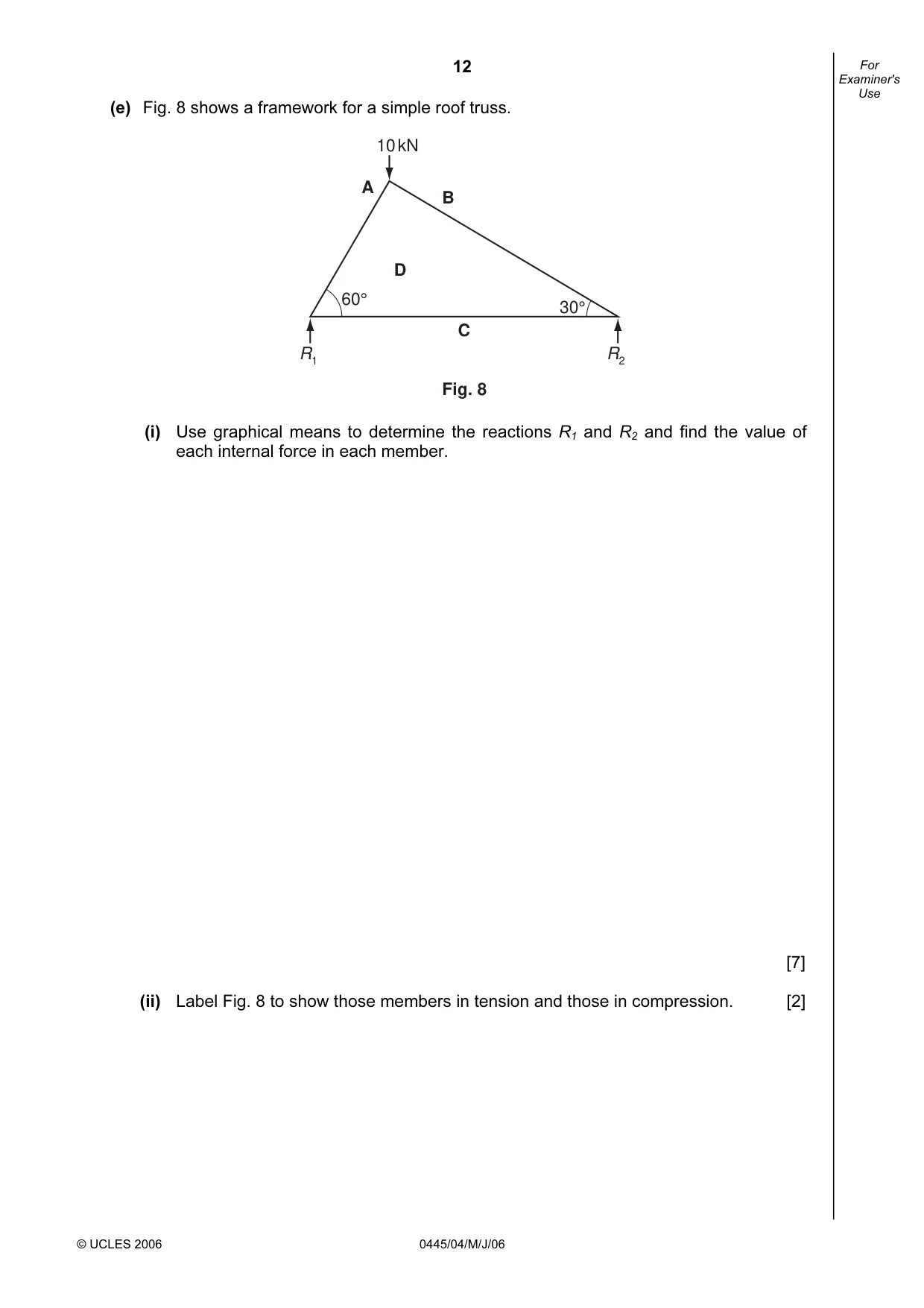
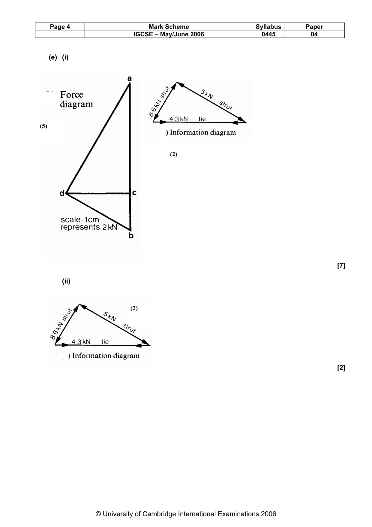
12 © UCLES 2006 0445/04/M/J/06 For Examiner's Use (e) Fig. 8 shows a framework for a simple roof truss. R1 R2 10 kN A B C 60° 30° D Fig. 8 (i) Use graphical means to determine the reactions R1 and R2 and find the value of each internal force in each member. [7] (ii) Label Fig. 8 to show those members in tension and those in compression. [2]
Question paper, page 13
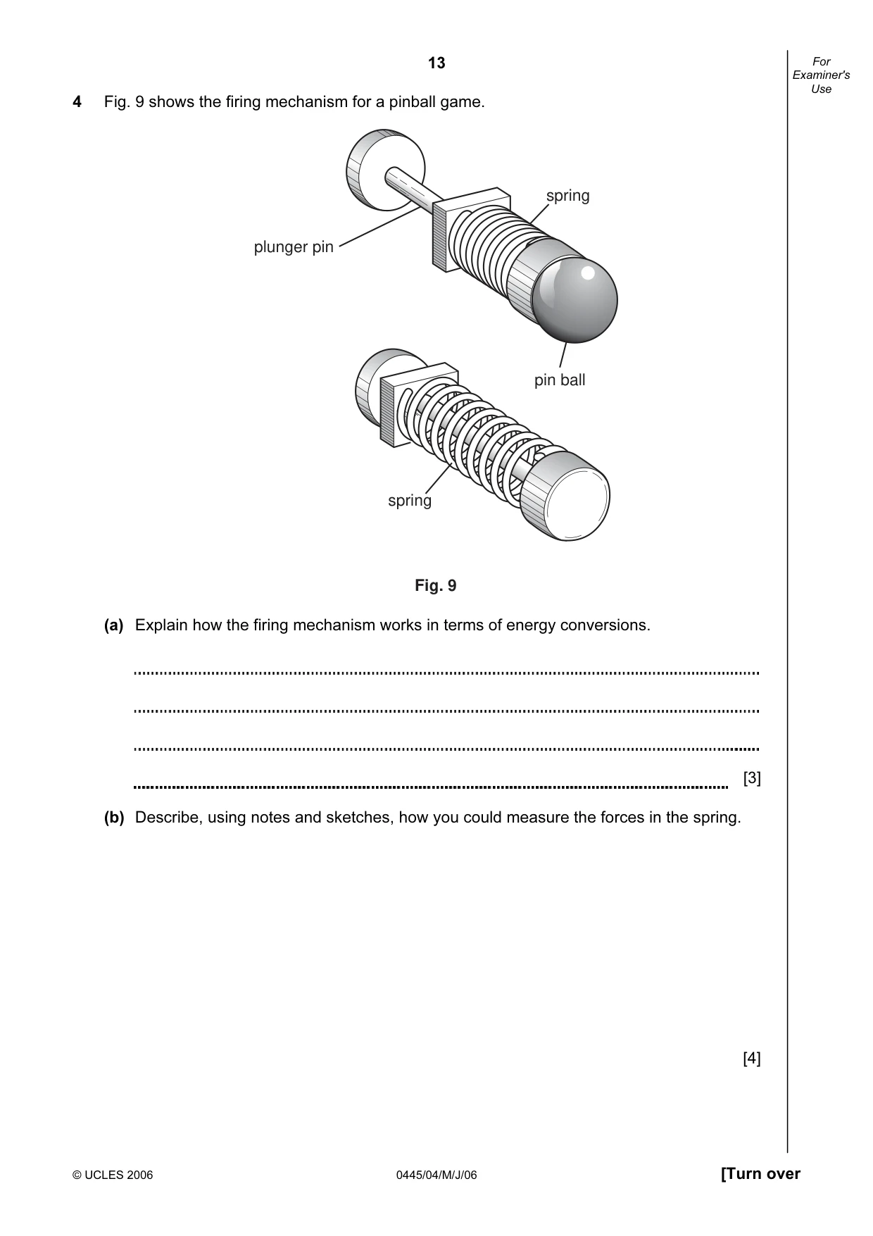
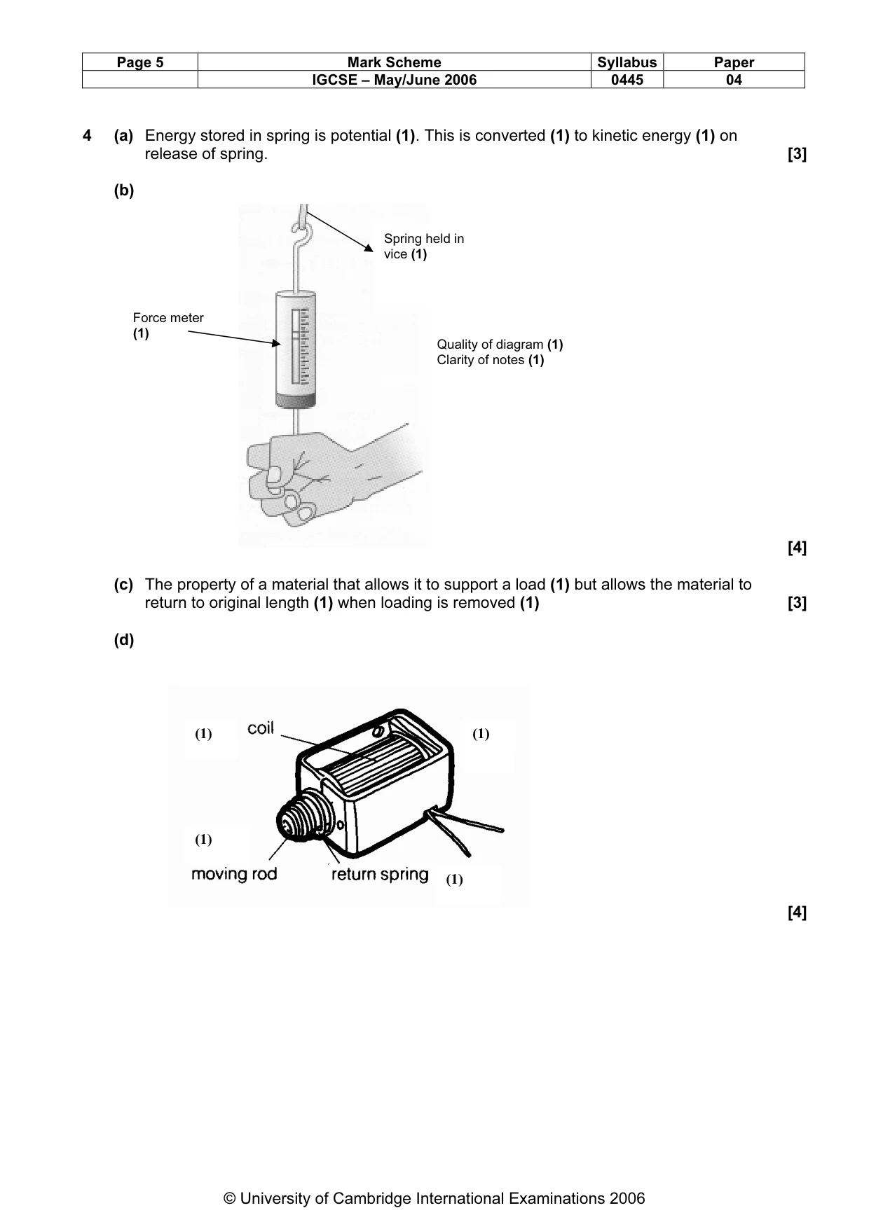
13 © UCLES 2006 0445/04/M/J/06 [Turn over For Examiner's Use 4 Fig. 9 shows the firing mechanism for a pinball game. plunger pin spring pin ball spring Fig. 9 (a) Explain how the firing mechanism works in terms of energy conversions. [3] (b) Describe, using notes and sketches, how you could measure the forces in the spring. [4]
Question paper, page 14
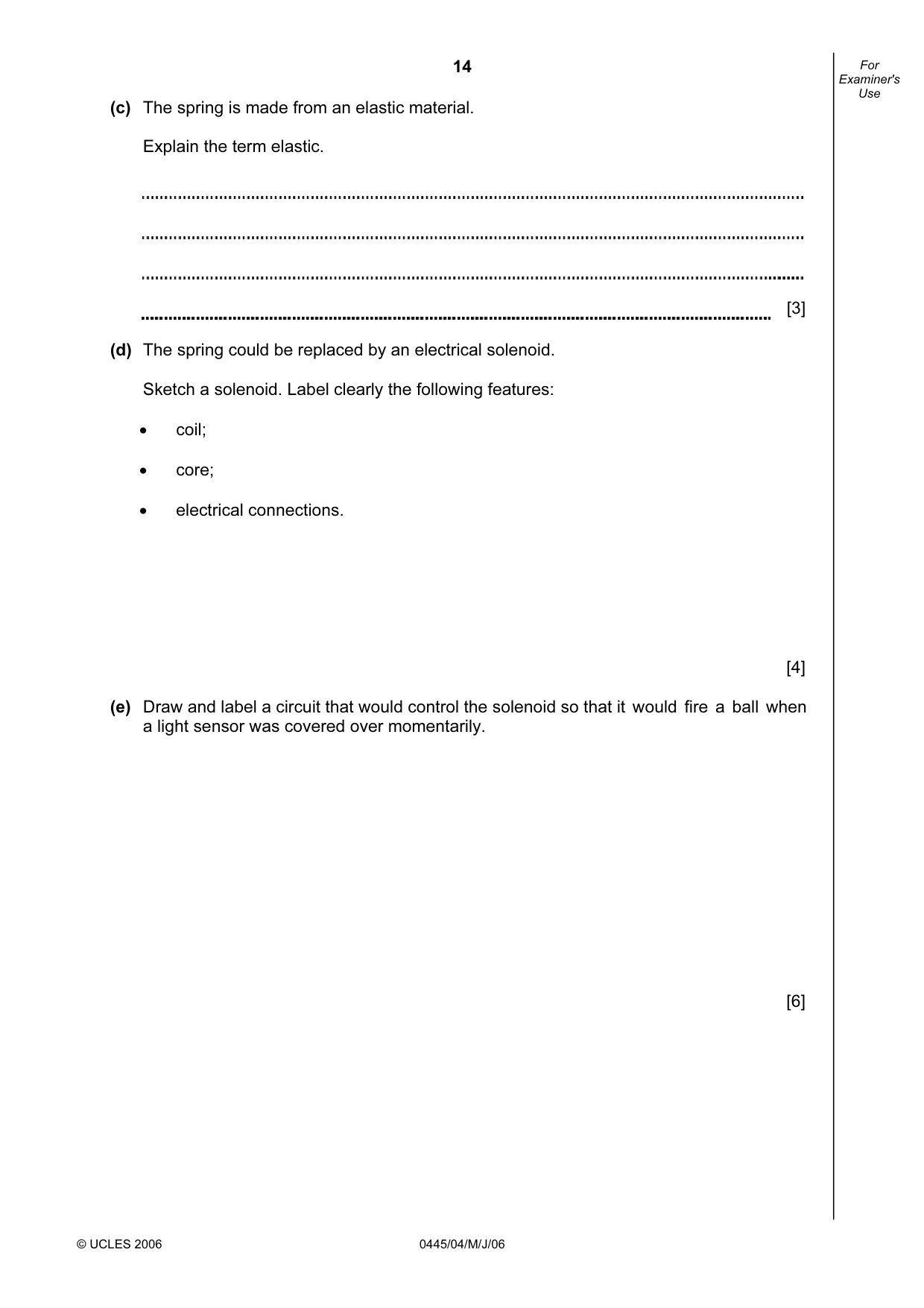
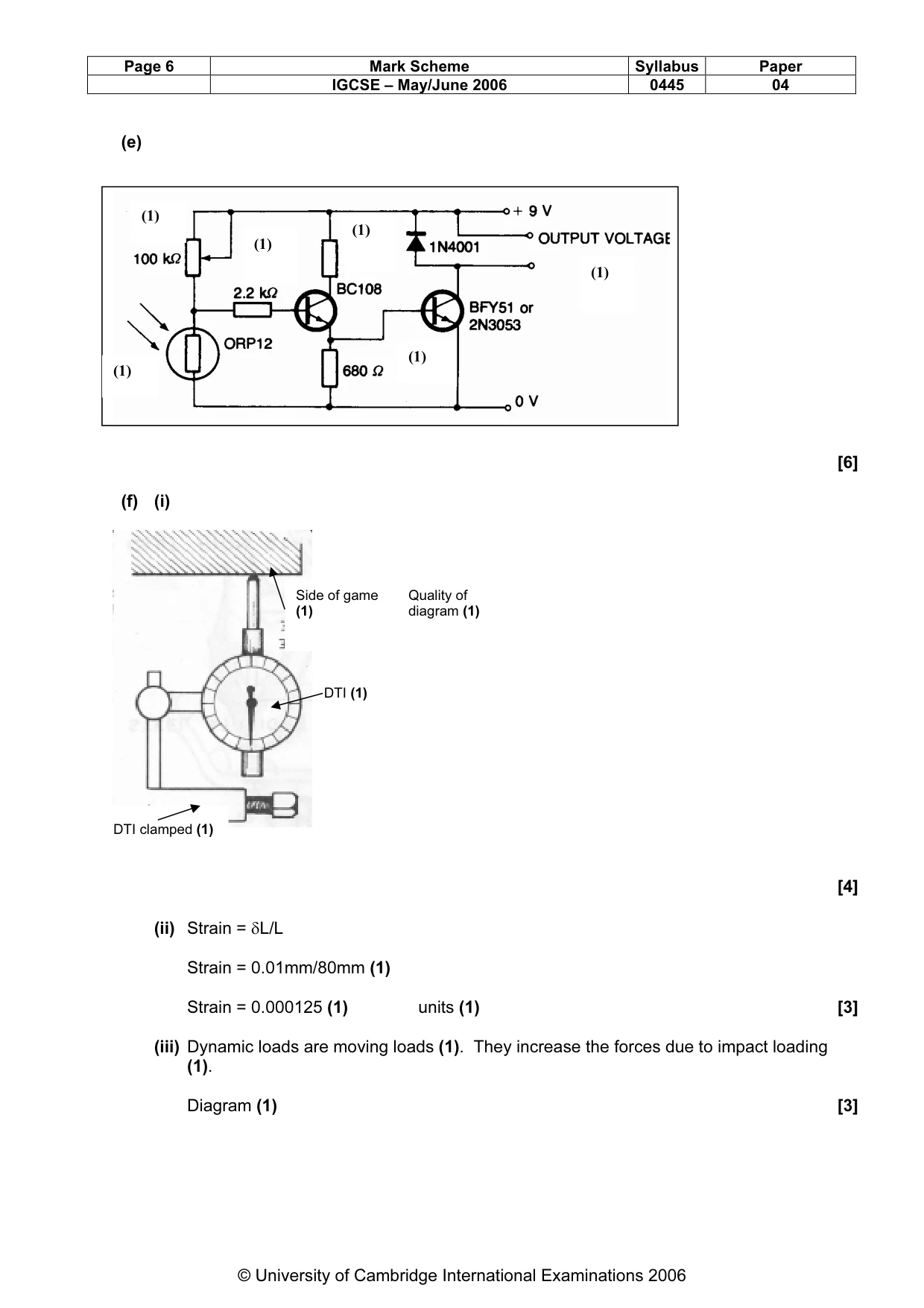
14 © UCLES 2006 0445/04/M/J/06 For Examiner's Use (c) The spring is made from an elastic material. Explain the term elastic. [3] (d) The spring could be replaced by an electrical solenoid. Sketch a solenoid. Label clearly the following features: • coil; • core; • electrical connections. [4] (e) Draw and label a circuit that would control the solenoid so that it would fire a ball when a light sensor was covered over momentarily. [6]
Question paper, page 15
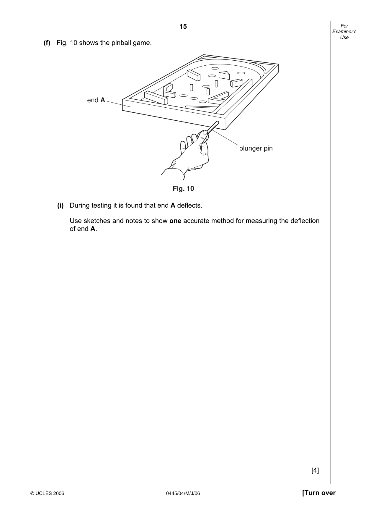
15 © UCLES 2006 0445/04/M/J/06 [Turn over For Examiner's Use (f) Fig. 10 shows the pinball game. end A plunger pin Fig. 10 (i) During testing it is found that end A deflects. Use sketches and notes to show one accurate method for measuring the deflection of end A. [4]
Question paper, page 16
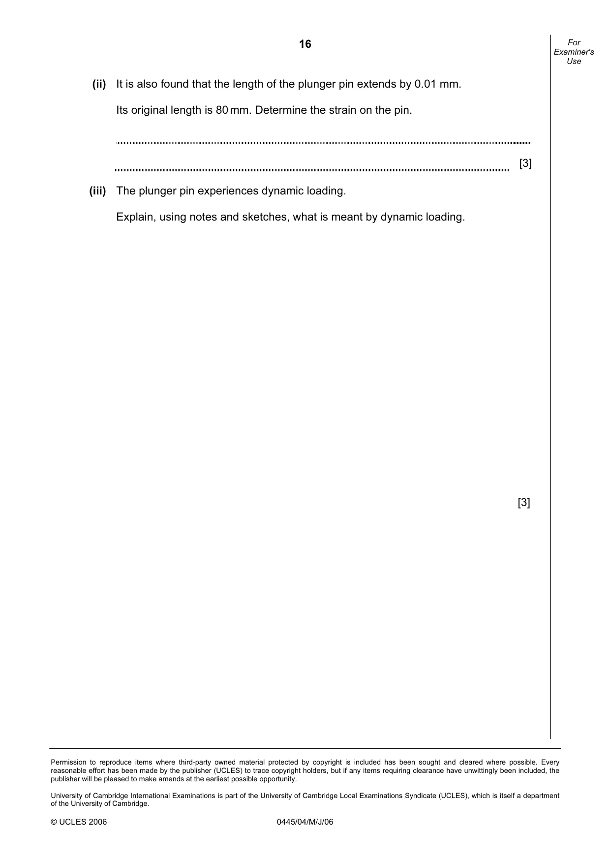
16 Permission to reproduce items where third-party owned material protected by copyright is included has been sought and cleared where possible. Every reasonable effort has been made by the publisher (UCLES) to trace copyright holders, but if any items requiring clearance have unwittingly been included, the publisher will be pleased to make amends at the earliest possible opportunity. University of Cambridge International Examinations is part of the University of Cambridge Local Examinations Syndicate (UCLES), which is itself a department of the University of Cambridge. © UCLES 2006 0445/04/M/J/06 For Examiner's Use (ii) It is also found that the length of the plunger pin extends by 0.01 mm. Its original length is 80 mm. Determine the strain on the pin. [3] (iii) The plunger pin experiences dynamic loading. Explain, using notes and sketches, what is meant by dynamic loading. [3]
Mark scheme, page 1
UNIVERSITY OF CAMBRIDGE INTERNATIONAL EXAMINATIONS International General Certificate of Secondary Education MARK SCHEME for the May/June 2006 question paper 0445 DESIGN AND TECHNOLOGY 0445/04 Paper 4, maximum raw mark 60 These mark schemes are published as an aid to teachers and students, to indicate the requirements of the examination. They show the basis on which Examiners were initially instructed to award marks. They do not indicate the details of the discussions that took place at an Examiners’ meeting before marking began. Any substantial changes to the mark scheme that arose from these discussions will be recorded in the published Report on the Examination. All Examiners are instructed that alternative correct answers and unexpected approaches in candidates’ scripts must be given marks that fairly reflect the relevant knowledge and skills demonstrated. Mark schemes must be read in conjunction with the question papers and the Report on the Examination. The minimum marks in these components needed for various grades were previously published with these mark schemes, but are now instead included in the Report on the Examination for this session. • CIE will not enter into discussion or correspondence in connection with these mark schemes. CIE is publishing the mark schemes for the May/June 2006 question papers for most IGCSE and GCE Advanced Level and Advanced Subsidiary Level syllabuses and some Ordinary Level syllabuses. www.XtremePapers.com
Mark scheme, page 2
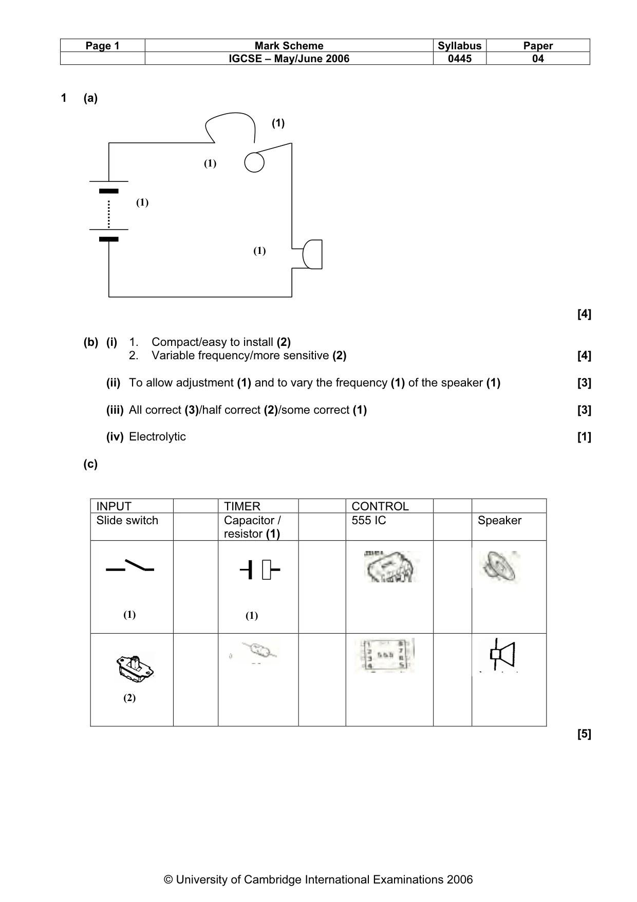
Page 1 Mark Scheme Syllabus Paper IGCSE – May/June 2006 0445 04 © University of Cambridge International Examinations 2006 1 (a) [4] (b) (i) 1. Compact/easy to install (2) 2. Variable frequency/more sensitive (2) [4] (ii) To allow adjustment (1) and to vary the frequency (1) of the speaker (1) [3] (iii) All correct (3)/half correct (2)/some correct (1) [3] (iv) Electrolytic [1] (c) INPUT TIMER CONTROL Slide switch Capacitor / resistor (1) 555 IC Speaker [5] (1) (1) (1) (1) (2) (1) (1)
Mark scheme, page 3
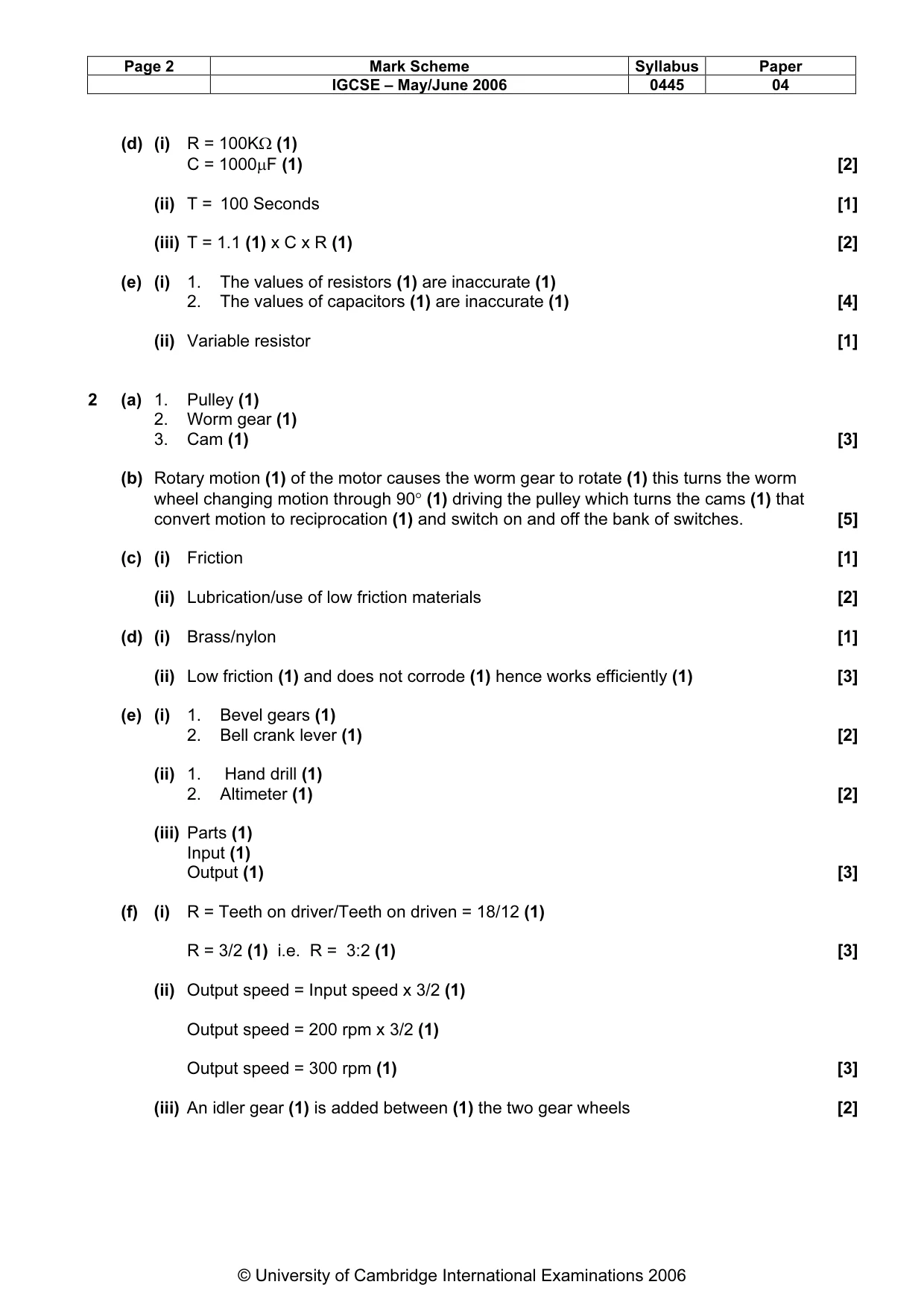
Page 2 Mark Scheme Syllabus Paper IGCSE – May/June 2006 0445 04 © University of Cambridge International Examinations 2006 (d) (i) R = 100KΩ (1) C = 1000µF (1) [2] (ii) T = 100 Seconds [1] (iii) T = 1.1 (1) x C x R (1) [2] (e) (i) 1. The values of resistors (1) are inaccurate (1) 2. The values of capacitors (1) are inaccurate (1) [4] (ii) Variable resistor [1] 2 (a) 1. Pulley (1) 2. Worm gear (1) 3. Cam (1) [3] (b) Rotary motion (1) of the motor causes the worm gear to rotate (1) this turns the worm wheel changing motion through 90° (1) driving the pulley which turns the cams (1) that convert motion to reciprocation (1) and switch on and off the bank of switches. [5] (c) (i) Friction [1] (ii) Lubrication/use of low friction materials [2] (d) (i) Brass/nylon [1] (ii) Low friction (1) and does not corrode (1) hence works efficiently (1) [3] (e) (i) 1. Bevel gears (1) 2. Bell crank lever (1) [2] (ii) 1. Hand drill (1) 2. Altimeter (1) [2] (iii) Parts (1) Input (1) Output (1) [3] (f) (i) R = Teeth on driver/Teeth on driven = 18/12 (1) R = 3/2 (1) i.e. R = 3:2 (1) [3] (ii) Output speed = Input speed x 3/2 (1) Output speed = 200 rpm x 3/2 (1) Output speed = 300 rpm (1) [3] (iii) An idler gear (1) is added between (1) the two gear wheels [2]
Mark scheme, page 4
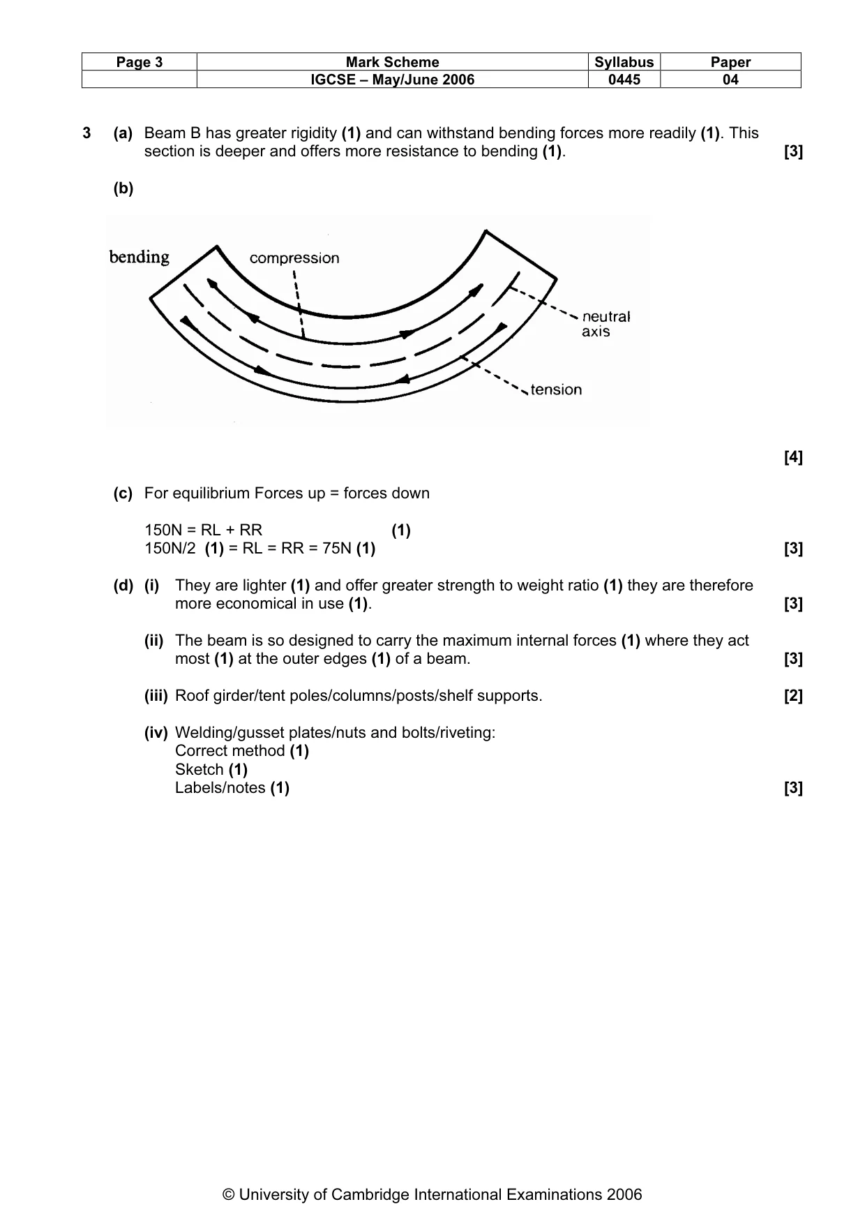
Page 3 Mark Scheme Syllabus Paper IGCSE – May/June 2006 0445 04 © University of Cambridge International Examinations 2006 3 (a) Beam B has greater rigidity (1) and can withstand bending forces more readily (1). This section is deeper and offers more resistance to bending (1). [3] (b) [4] (c) For equilibrium Forces up = forces down 150N = RL + RR (1) 150N/2 (1) = RL = RR = 75N (1) [3] (d) (i) They are lighter (1) and offer greater strength to weight ratio (1) they are therefore more economical in use (1). [3] (ii) The beam is so designed to carry the maximum internal forces (1) where they act most (1) at the outer edges (1) of a beam. [3] (iii) Roof girder/tent poles/columns/posts/shelf supports. [2] (iv) Welding/gusset plates/nuts and bolts/riveting: Correct method (1) Sketch (1) Labels/notes (1) [3]
Mark scheme, page 5
Page 4 Mark Scheme Syllabus Paper IGCSE – May/June 2006 0445 04 © University of Cambridge International Examinations 2006 (e) (i) [7] (ii) [2] (5) (2) (2)
Mark scheme, page 6
Page 5 Mark Scheme Syllabus Paper IGCSE – May/June 2006 0445 04 © University of Cambridge International Examinations 2006 4 (a) Energy stored in spring is potential (1). This is converted (1) to kinetic energy (1) on release of spring. [3] (b) [4] (c) The property of a material that allows it to support a load (1) but allows the material to return to original length (1) when loading is removed (1) [3] (d) [4] Spring held in vice (1) Force meter (1) Quality of diagram (1) Clarity of notes (1) (1) (1) (1) (1)
Mark scheme, page 7
Page 6 Mark Scheme Syllabus Paper IGCSE – May/June 2006 0445 04 © University of Cambridge International Examinations 2006 (e) [6] (f) (i) [4] (ii) Strain = δL/L Strain = 0.01mm/80mm (1) Strain = 0.000125 (1) units (1) [3] (iii) Dynamic loads are moving loads (1). They increase the forces due to impact loading (1). Diagram (1) [3] (1) (1) (1) (1) (1) (1) Side of game (1) DTI (1) DTI clamped (1) Quality of diagram (1)
What you needed in this session
Cambridge’s own grade thresholds for 2006 May/June, Paper 4 · Variant 1. A higher threshold means an easier paper — the bar moves with how the cohort did.