Cambridge IGCSE Design and Technology 0445 — 2005 Oct/Nov Paper 4 · Variant 1
0445/41/O/N/05
The question paper and its mark scheme, free to read here and free to download. This is Cambridge’s own paper, exactly as it was sat.
Question paper20 pages


Mark scheme6 pages
Answers below. Sit the paper first if you are practising.
Paper as text
Question paper, page 1
This document consists of 18 printed pages and 2 blank pages. SPA (KN) S80505/2 © UCLES 2005 [Turn over UNIVERSITY OF CAMBRIDGE INTERNATIONAL EXAMINATIONS International General Certificate of Secondary Education DESIGN AND TECHNOLOGY 0445/04 Paper 4 Technology October/November 2005 1 hour Candidates answer on the Question Paper. No additional materials are required. To be taken together with Paper 1 in one session of 2 hours 45 minutes. READ THESE INSTRUCTIONS FIRST Write your Centre number, candidate number and name on all the work you hand in. Write in dark blue or black pen in the spaces provided on the Question Paper. You may use a soft pencil for any diagrams, graphs or rough working. Do not use staples, paper clips, highlighters, glue or correction fluid. Answer any two questions. The number of marks is given in brackets [ ] at the end of each question or part question. You may use a calculator. Centre Number Candidate Number Name If you have been given a label, look at the details. If any details are incorrect or missing, please fill in your correct details in the space given at the top of this page. Stick your personal label here, if provided. For Examiner’s Use 1 2 3 4 TOTAL www.XtremePapers.com
Question paper, page 2
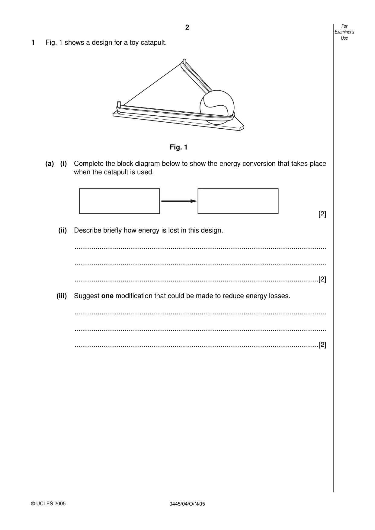
2 0445/04/O/N/05 1 Fig. 1 shows a design for a toy catapult. Fig. 1 (a) (i) Complete the block diagram below to show the energy conversion that takes place when the catapult is used. [2] (ii) Describe briefly how energy is lost in this design. … … …[2] (iii) Suggest one modification that could be made to reduce energy losses. … … …[2] For Examiner’s Use © UCLES 2005
Question paper, page 3
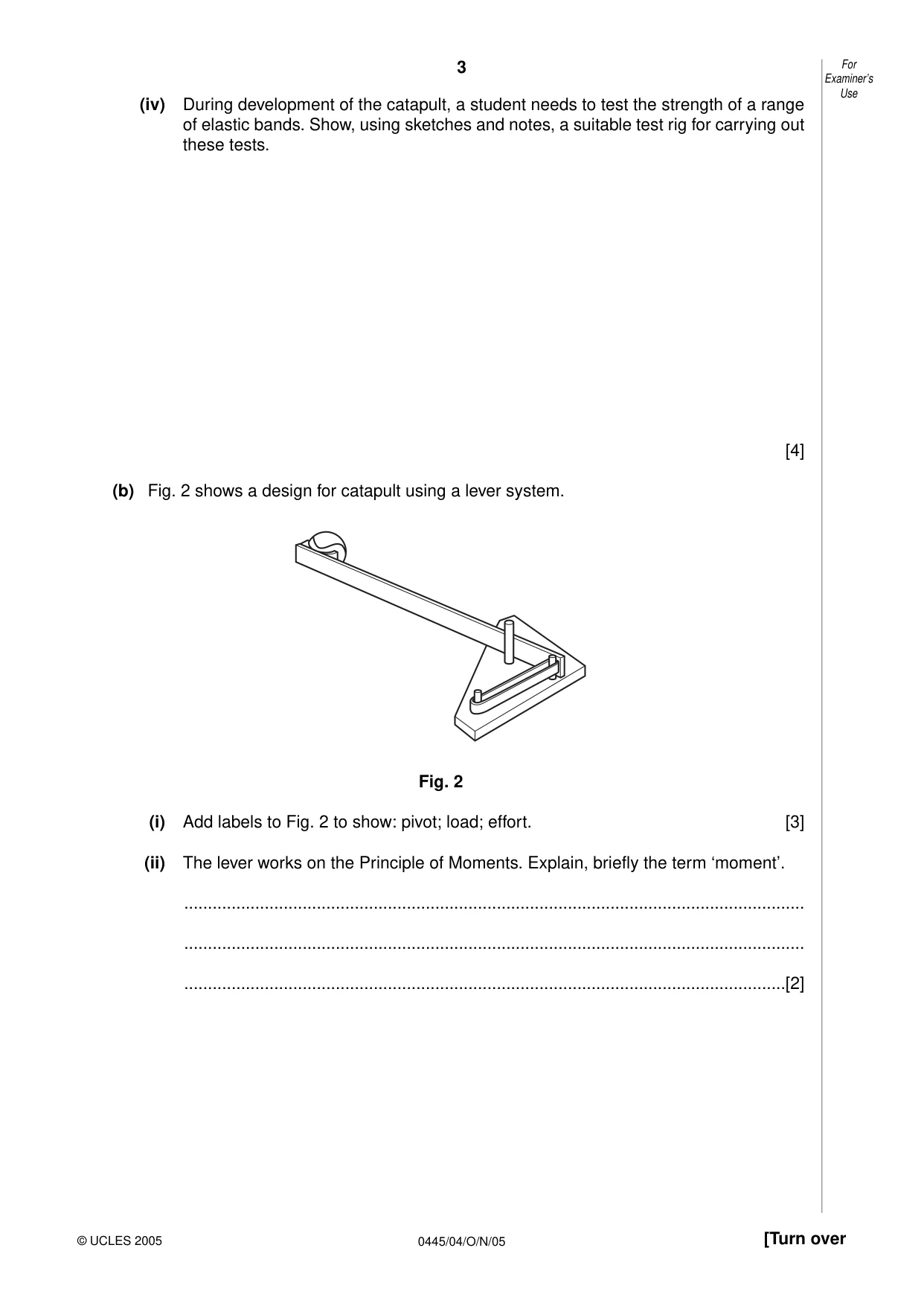
3 0445/04/O/N/05 [Turn over (iv) During development of the catapult, a student needs to test the strength of a range of elastic bands. Show, using sketches and notes, a suitable test rig for carrying out these tests. [4] (b) Fig. 2 shows a design for catapult using a lever system. Fig. 2 (i) Add labels to Fig. 2 to show: pivot; load; effort. [3] (ii) The lever works on the Principle of Moments. Explain, briefly the term ‘moment’. … … …[2] For Examiner’s Use © UCLES 2005
Question paper, page 4
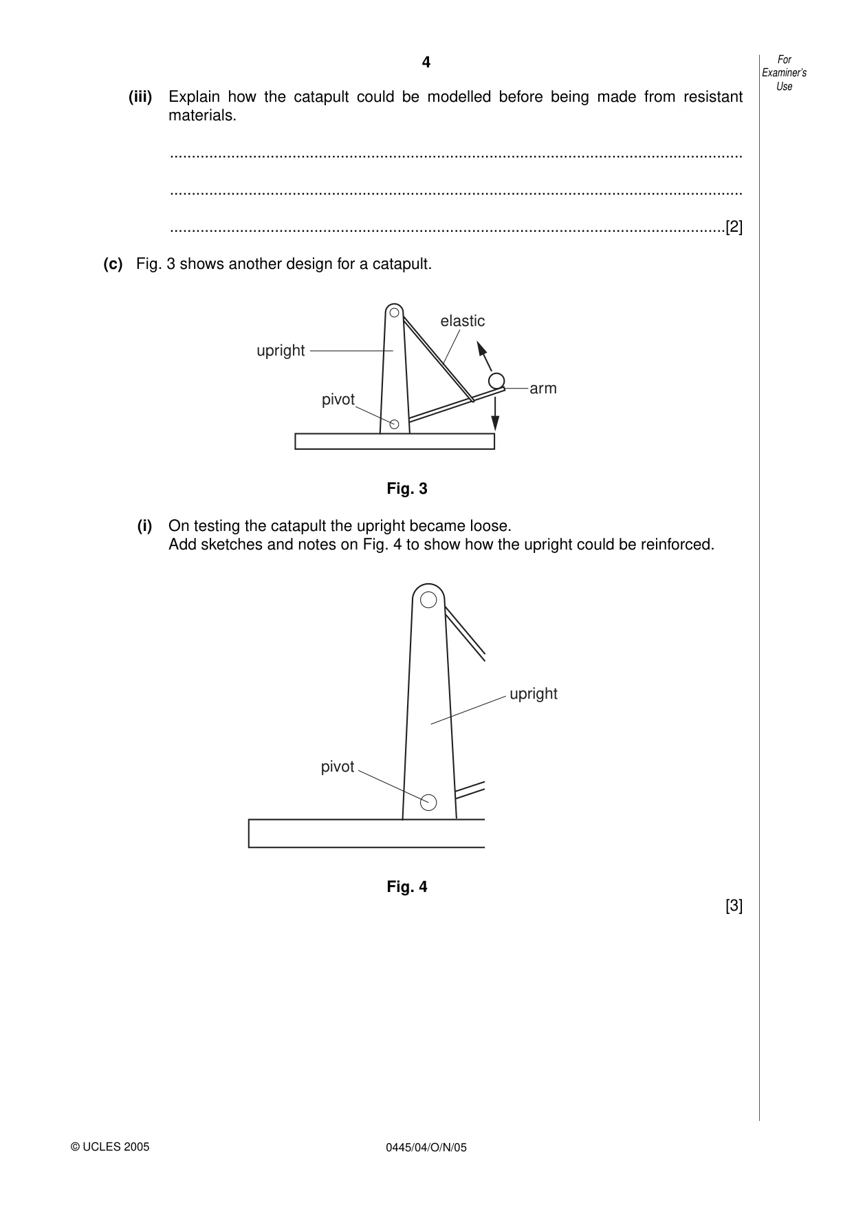
4 0445/04/O/N/05 (iii) Explain how the catapult could be modelled before being made from resistant materials. … … …[2] (c) Fig. 3 shows another design for a catapult. Fig. 3 (i) On testing the catapult the upright became loose. Add sketches and notes on Fig. 4 to show how the upright could be reinforced. Fig. 4 [3] pivot upright arm elastic pivot upright For Examiner’s Use © UCLES 2005
Question paper, page 5
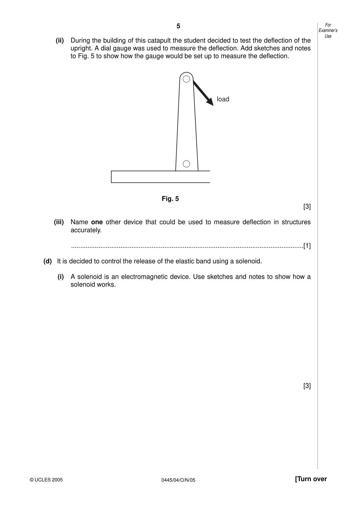
5 0445/04/O/N/05 [Turn over (ii) During the building of this catapult the student decided to test the deflection of the upright. A dial gauge was used to measure the deflection. Add sketches and notes to Fig. 5 to show how the gauge would be set up to measure the deflection. Fig. 5 [3] (iii) Name one other device that could be used to measure deflection in structures accurately. …[1] (d) It is decided to control the release of the elastic band using a solenoid. (i) A solenoid is an electromagnetic device. Use sketches and notes to show how a solenoid works. [3] load For Examiner’s Use © UCLES 2005
Question paper, page 6
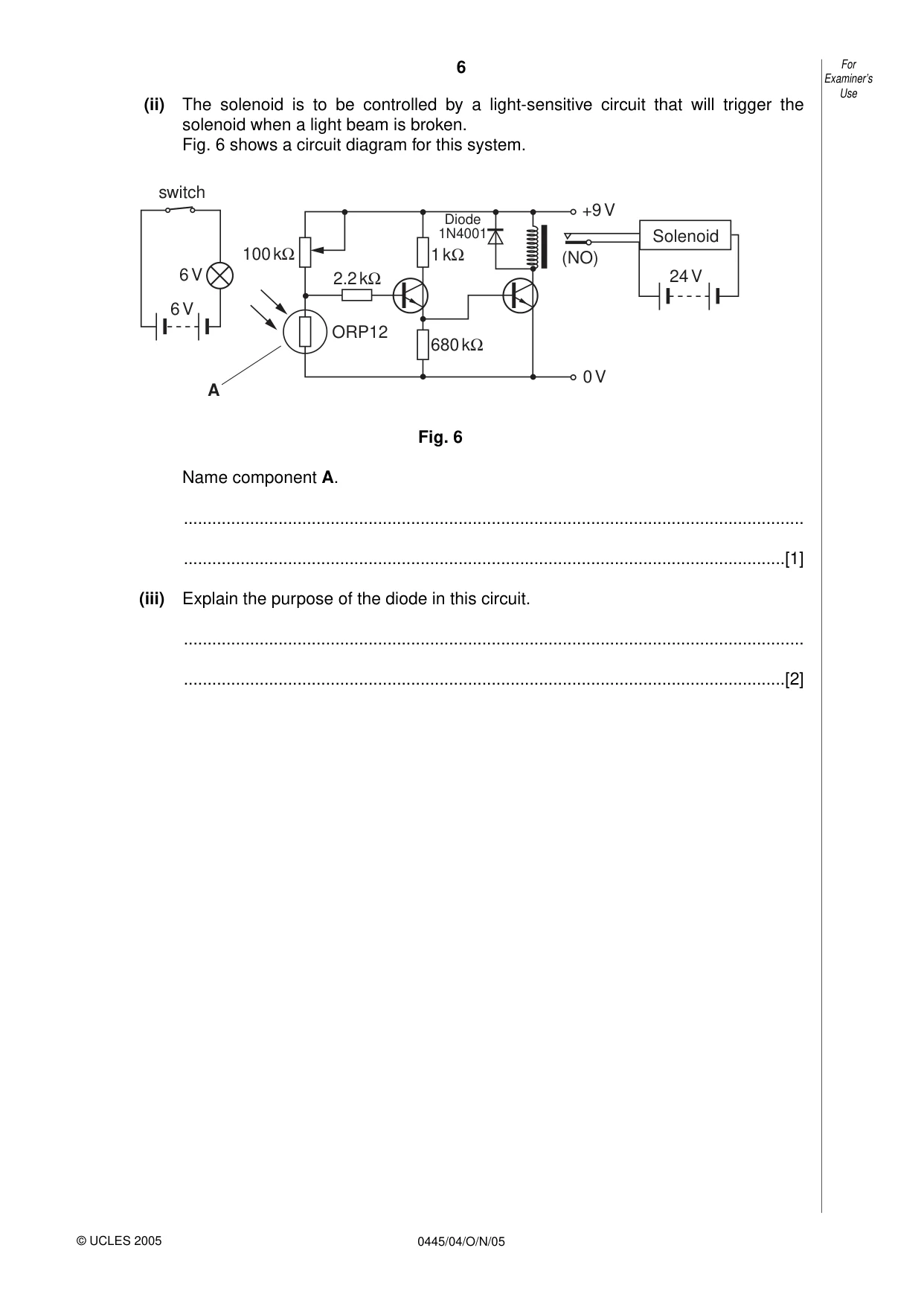
6 0445/04/O/N/05 (ii) The solenoid is to be controlled by a light-sensitive circuit that will trigger the solenoid when a light beam is broken. Fig. 6 shows a circuit diagram for this system. Fig. 6 Name component A. … …[1] (iii) Explain the purpose of the diode in this circuit. … …[2] Solenoid 24 V 6 V 6 V +9 V 0 V 1 kΩ 2.2 kΩ 100 kΩ ORP12 680 kΩ (NO) Diode 1N4001 A switch For Examiner’s Use © UCLES 2005
Question paper, page 7
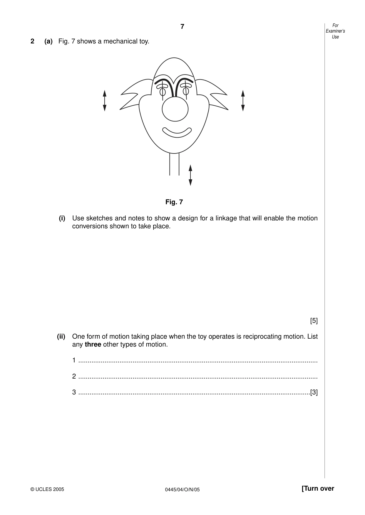
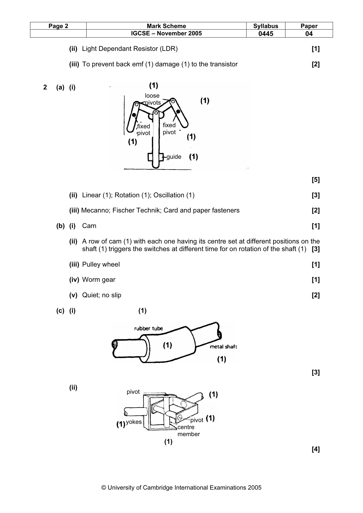
7 0445/04/O/N/05 [Turn over 2 (a) Fig. 7 shows a mechanical toy. Fig. 7 (i) Use sketches and notes to show a design for a linkage that will enable the motion conversions shown to take place. [5] (ii) One form of motion taking place when the toy operates is reciprocating motion. List any three other types of motion. 1 … 2 … 3 …[3] For Examiner’s Use © UCLES 2005
Question paper, page 8
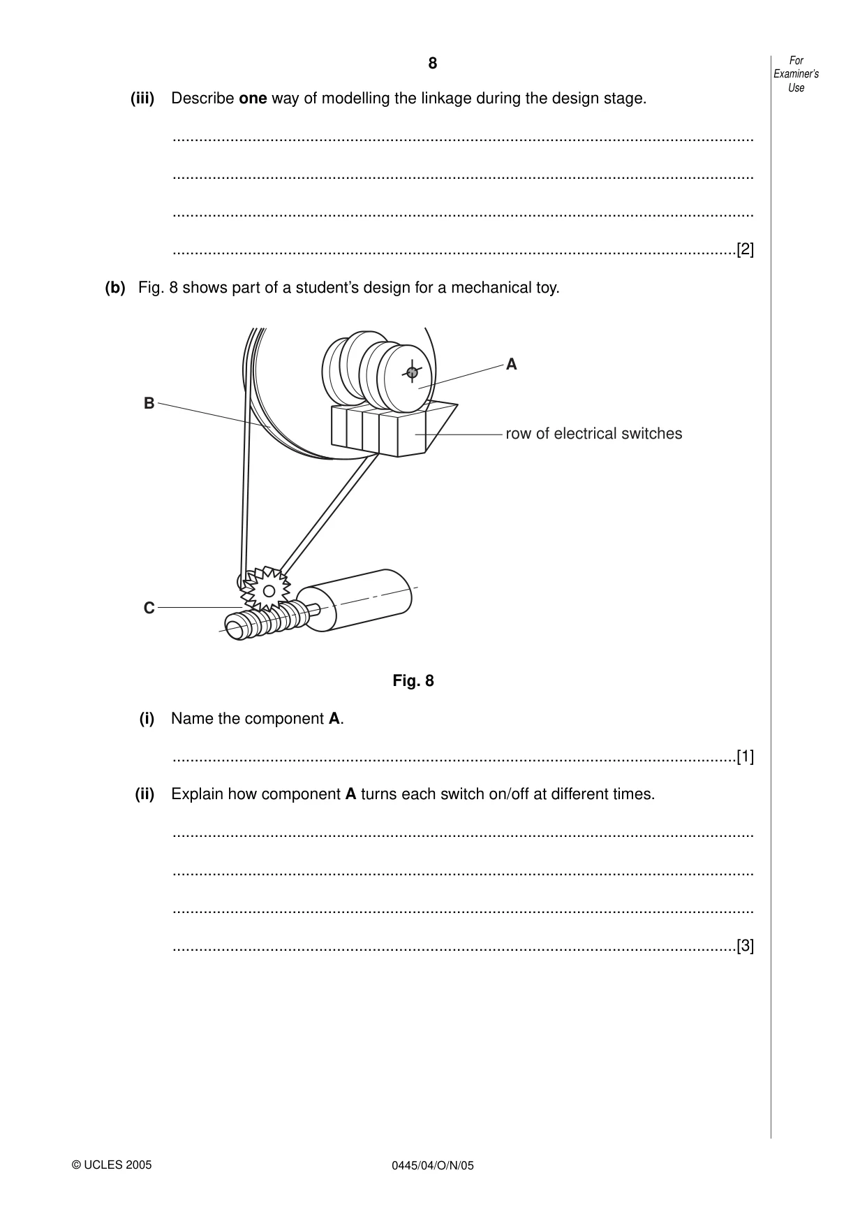
8 0445/04/O/N/05 (iii) Describe one way of modelling the linkage during the design stage. … … … …[2] (b) Fig. 8 shows part of a student’s design for a mechanical toy. Fig. 8 (i) Name the component A. …[1] (ii) Explain how component A turns each switch on/off at different times. … … … …[3] A B C row of electrical switches For Examiner’s Use © UCLES 2005
Question paper, page 9
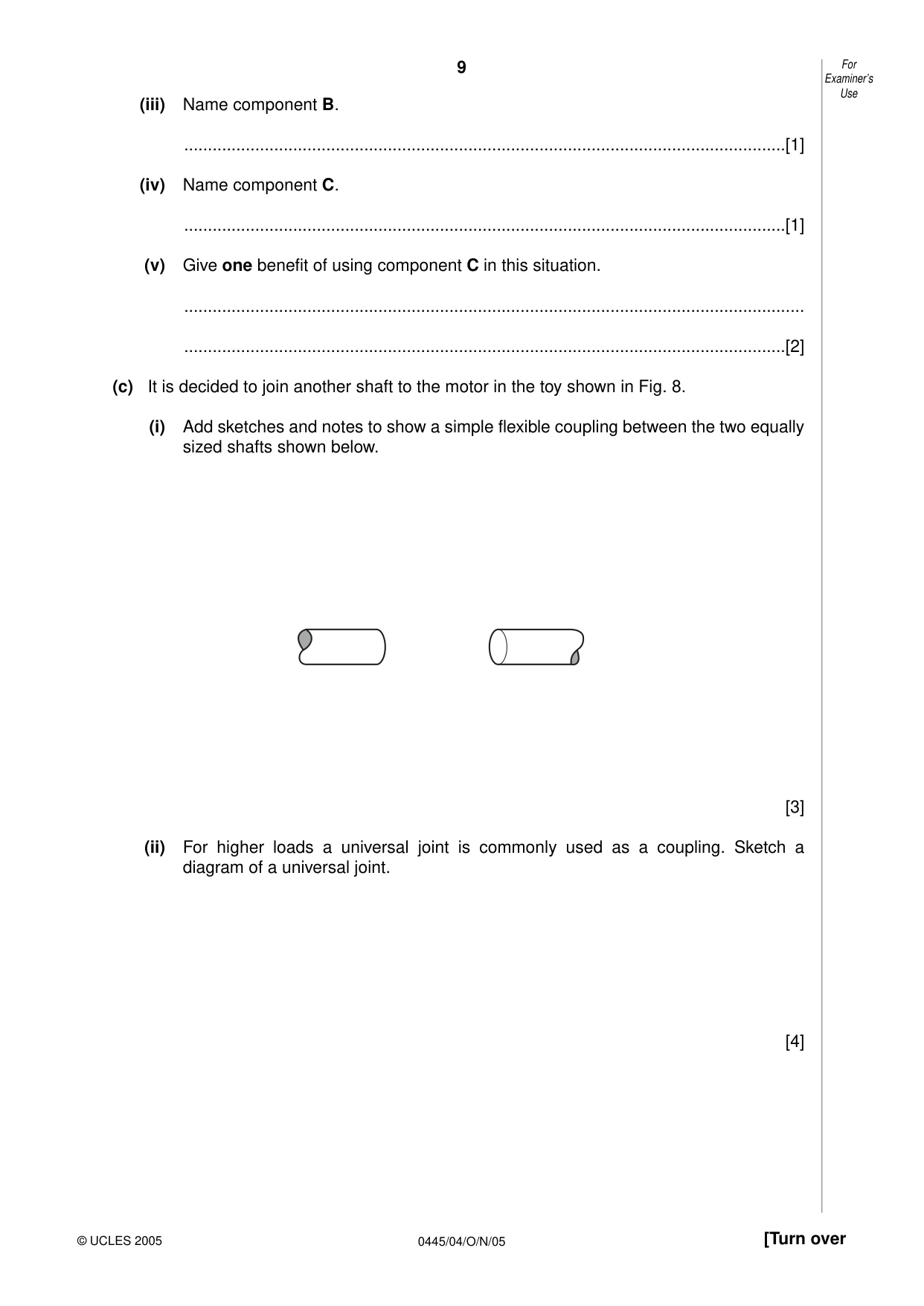
9 0445/04/O/N/05 [Turn over (iii) Name component B. …[1] (iv) Name component C. …[1] (v) Give one benefit of using component C in this situation. … …[2] (c) It is decided to join another shaft to the motor in the toy shown in Fig. 8. (i) Add sketches and notes to show a simple flexible coupling between the two equally sized shafts shown below. [3] (ii) For higher loads a universal joint is commonly used as a coupling. Sketch a diagram of a universal joint. [4] For Examiner’s Use © UCLES 2005
Question paper, page 10
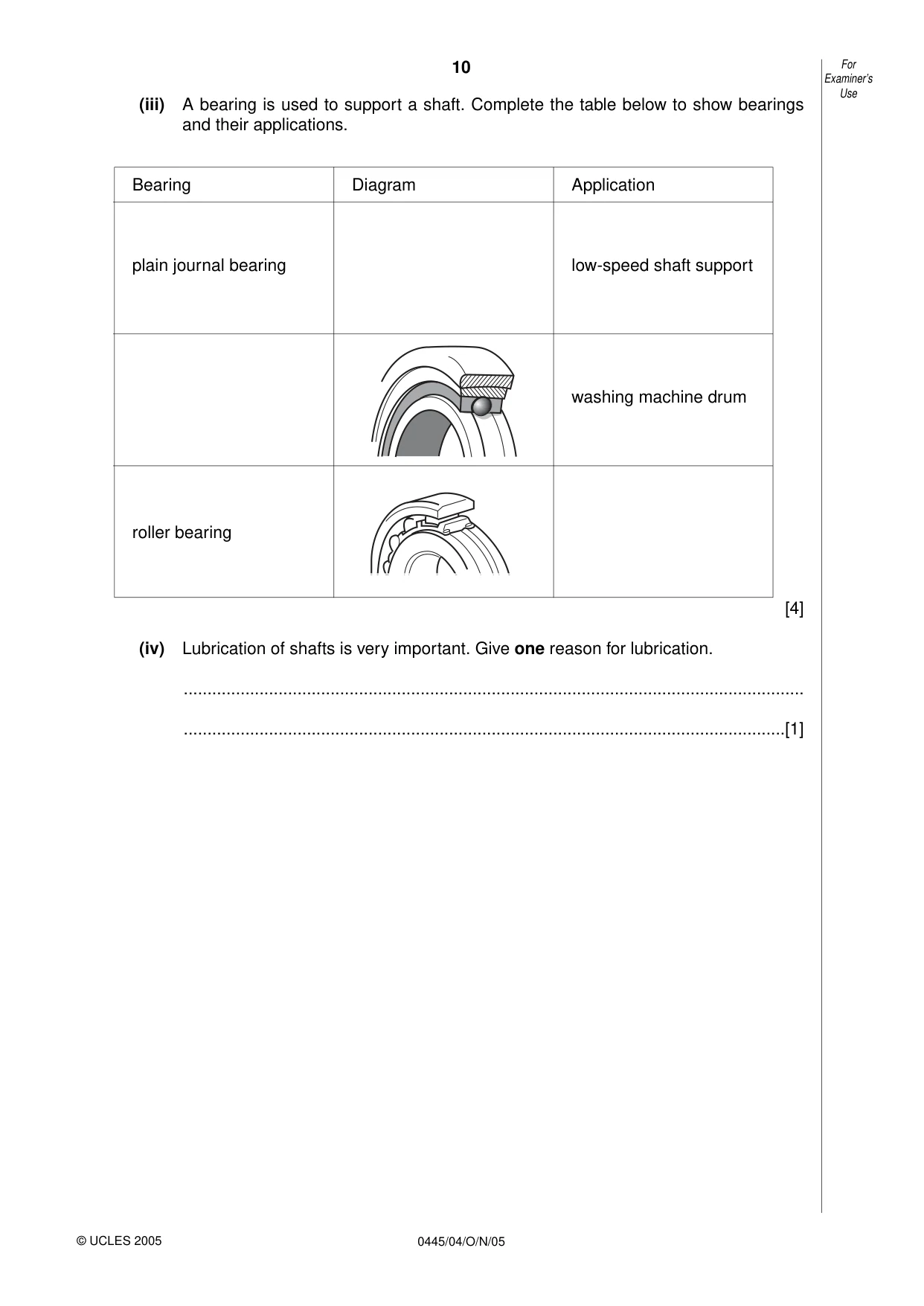
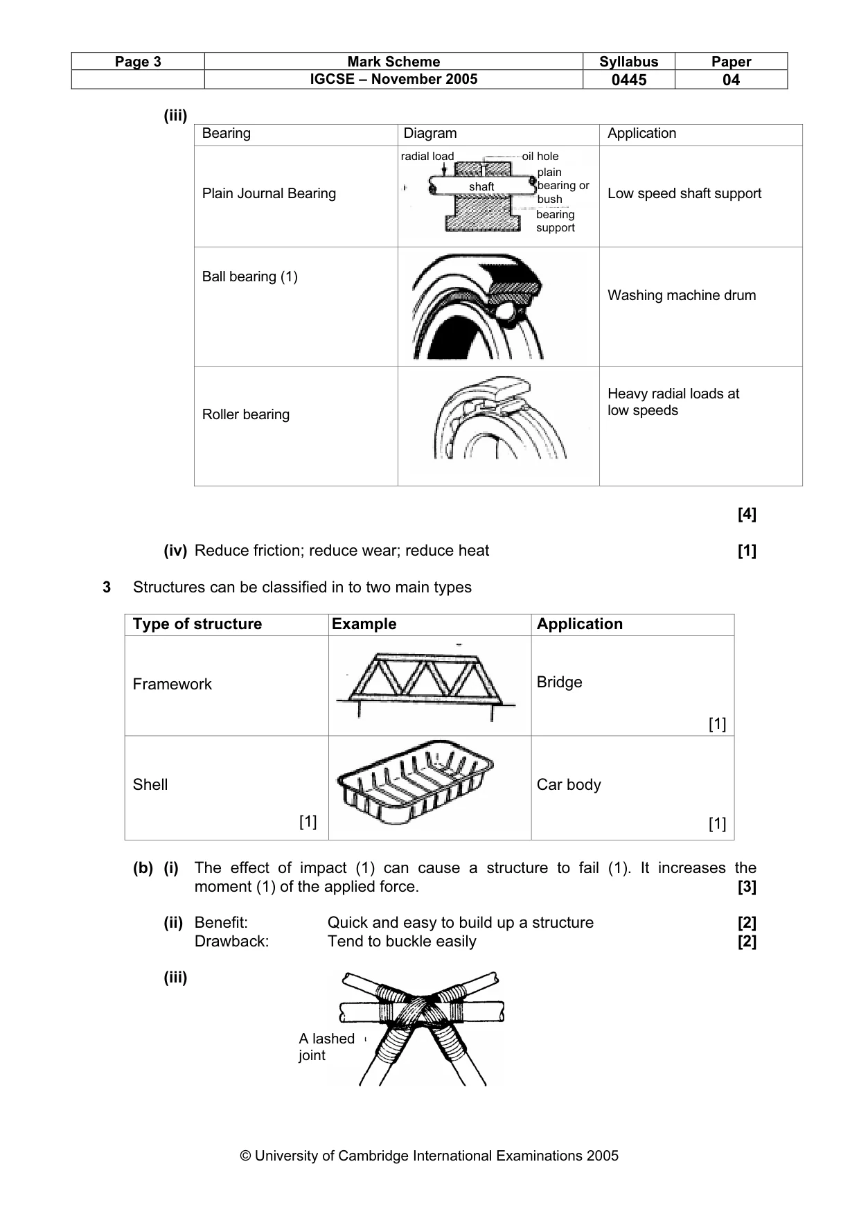
10 0445/04/O/N/05 (iii) A bearing is used to support a shaft. Complete the table below to show bearings and their applications. [4] (iv) Lubrication of shafts is very important. Give one reason for lubrication. … …[1] For Examiner’s Use © UCLES 2005 Bearing Diagram Application plain journal bearing low-speed shaft support washing machine drum roller bearing
Question paper, page 11
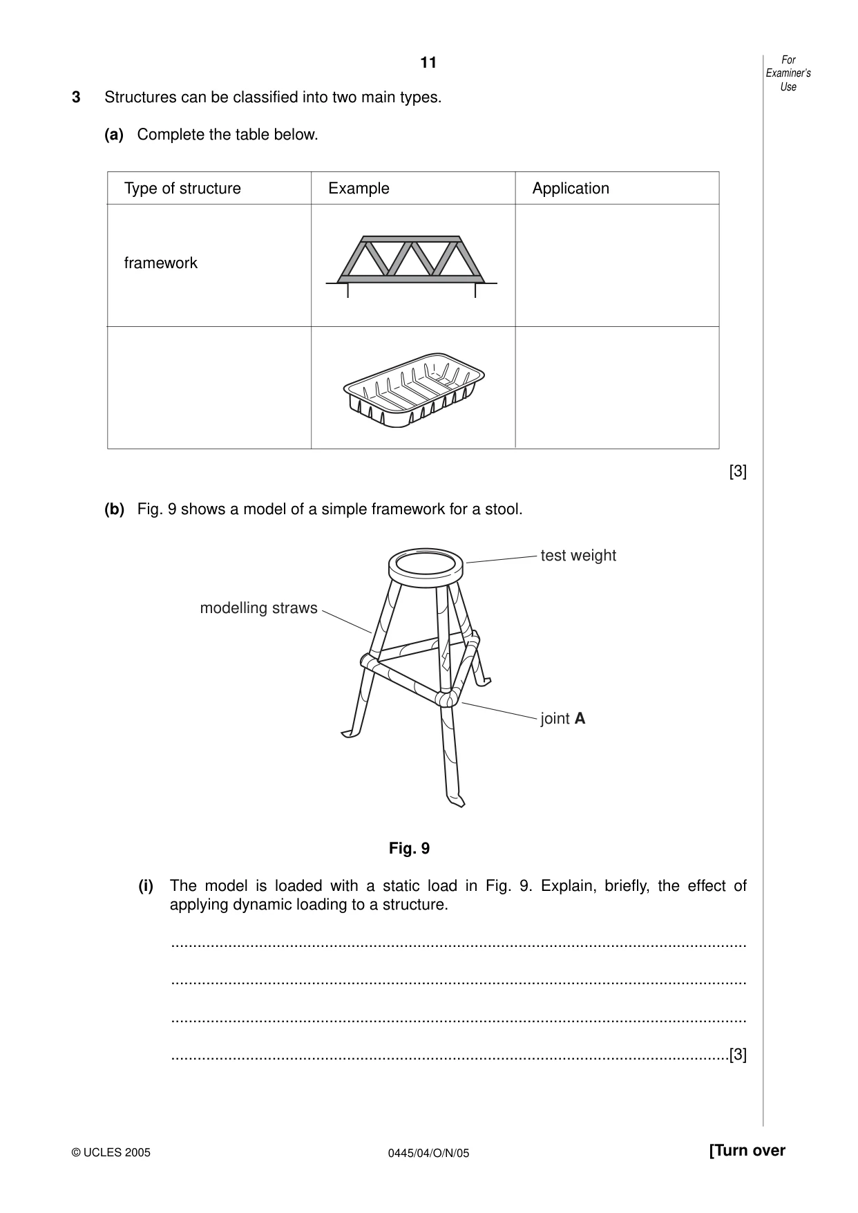
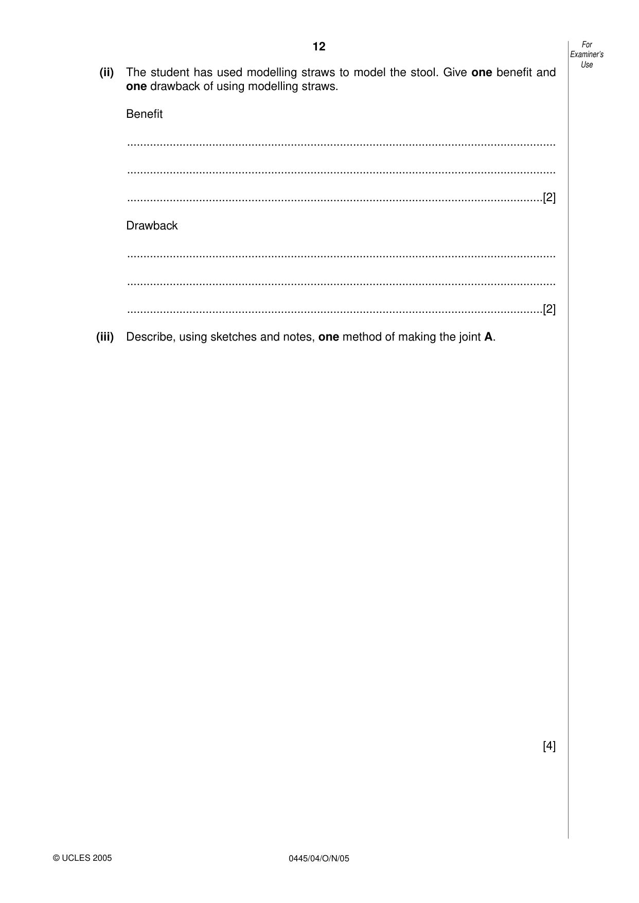
11 0445/04/O/N/05 [Turn over 3 Structures can be classified into two main types. (a) Complete the table below. [3] (b) Fig. 9 shows a model of a simple framework for a stool. Fig. 9 (i) The model is loaded with a static load in Fig. 9. Explain, briefly, the effect of applying dynamic loading to a structure. … … … …[3] test weight joint A modelling straws For Examiner’s Use © UCLES 2005 Type of structure Example Application framework
Question paper, page 12
12 0445/04/O/N/05 (ii) The student has used modelling straws to model the stool. Give one benefit and one drawback of using modelling straws. Benefit … … …[2] Drawback … … …[2] (iii) Describe, using sketches and notes, one method of making the joint A. [4] For Examiner’s Use © UCLES 2005
Question paper, page 13
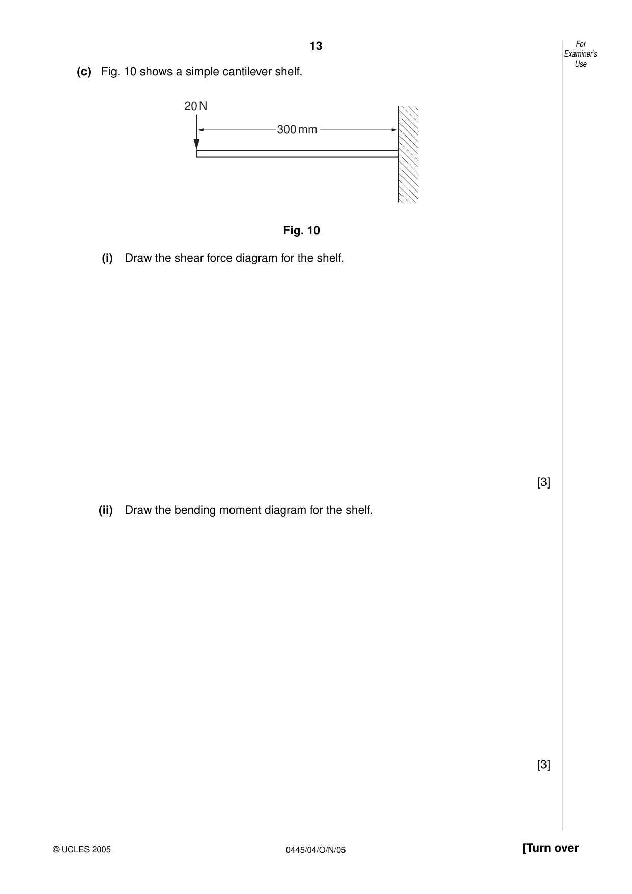
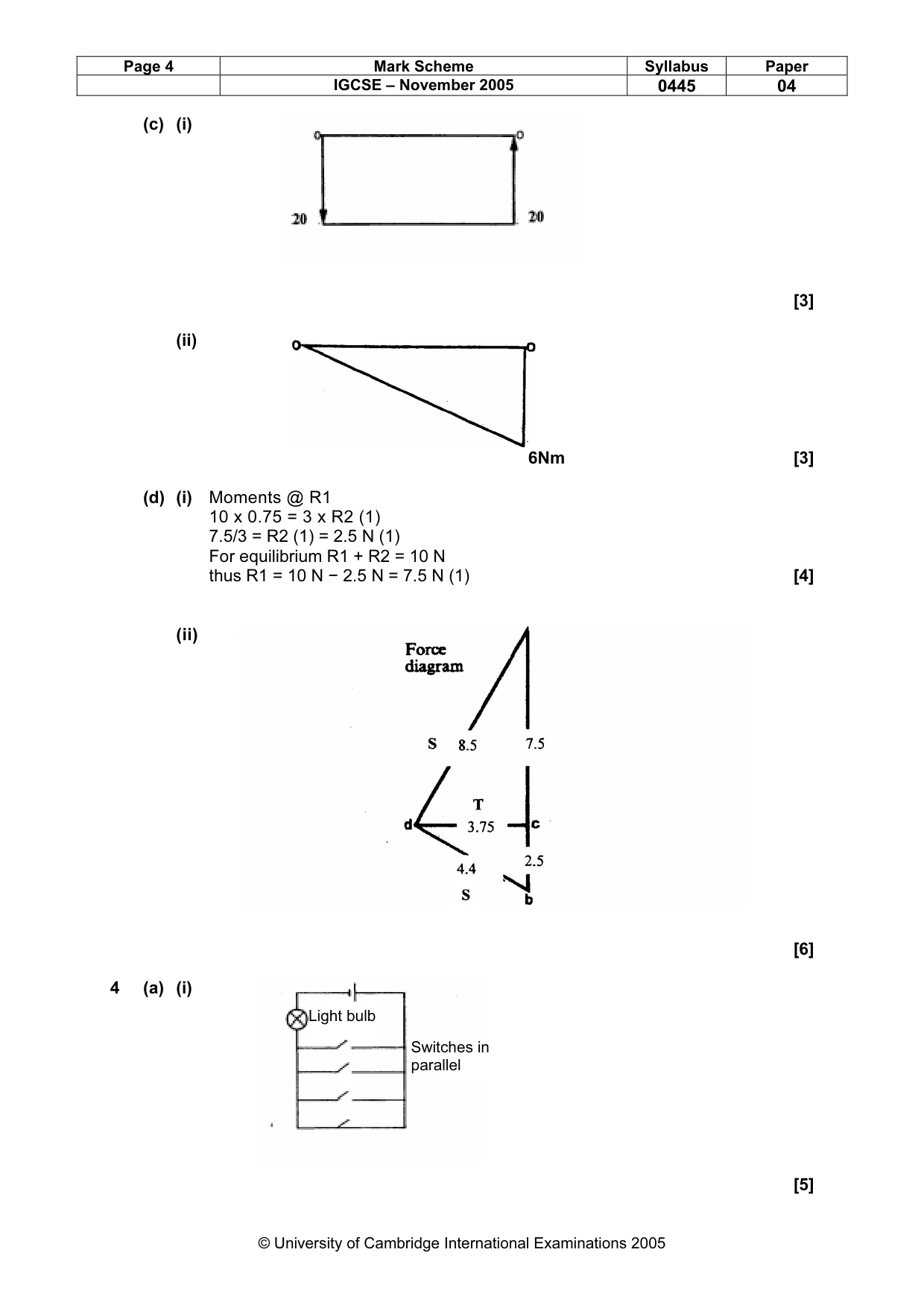
13 0445/04/O/N/05 [Turn over (c) Fig. 10 shows a simple cantilever shelf. Fig. 10 (i) Draw the shear force diagram for the shelf. [3] (ii) Draw the bending moment diagram for the shelf. [3] 300 mm 20 N For Examiner’s Use © UCLES 2005
Question paper, page 14
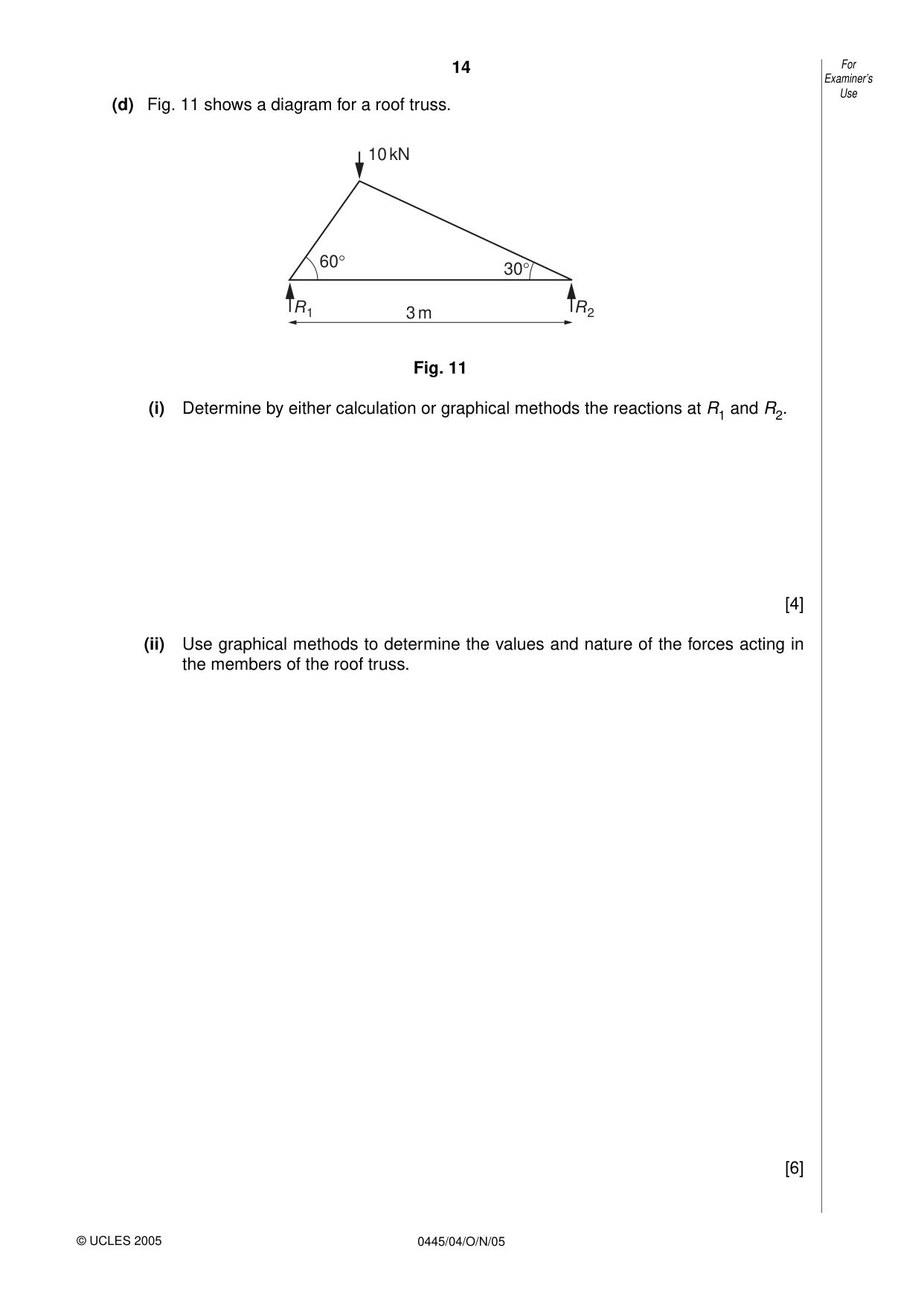
14 0445/04/O/N/05 (d) Fig. 11 shows a diagram for a roof truss. Fig. 11 (i) Determine by either calculation or graphical methods the reactions at R1 and R2. [4] (ii) Use graphical methods to determine the values and nature of the forces acting in the members of the roof truss. [6] 60° 30° 10 kN 3 m R1 R2 For Examiner’s Use © UCLES 2005
Question paper, page 15
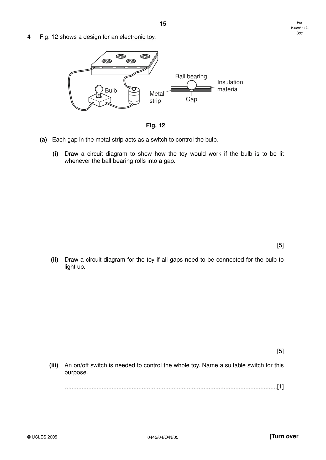
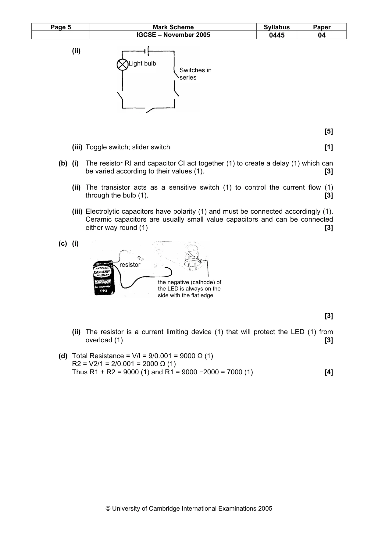
15 0445/04/O/N/05 [Turn over 4 Fig. 12 shows a design for an electronic toy. Fig. 12 (a) Each gap in the metal strip acts as a switch to control the bulb. (i) Draw a circuit diagram to show how the toy would work if the bulb is to be lit whenever the ball bearing rolls into a gap. [5] (ii) Draw a circuit diagram for the toy if all gaps need to be connected for the bulb to light up. [5] (iii) An on/off switch is needed to control the whole toy. Name a suitable switch for this purpose. …[1] Bulb Ball bearing Gap Insulation material Metal strip For Examiner’s Use © UCLES 2005
Question paper, page 16
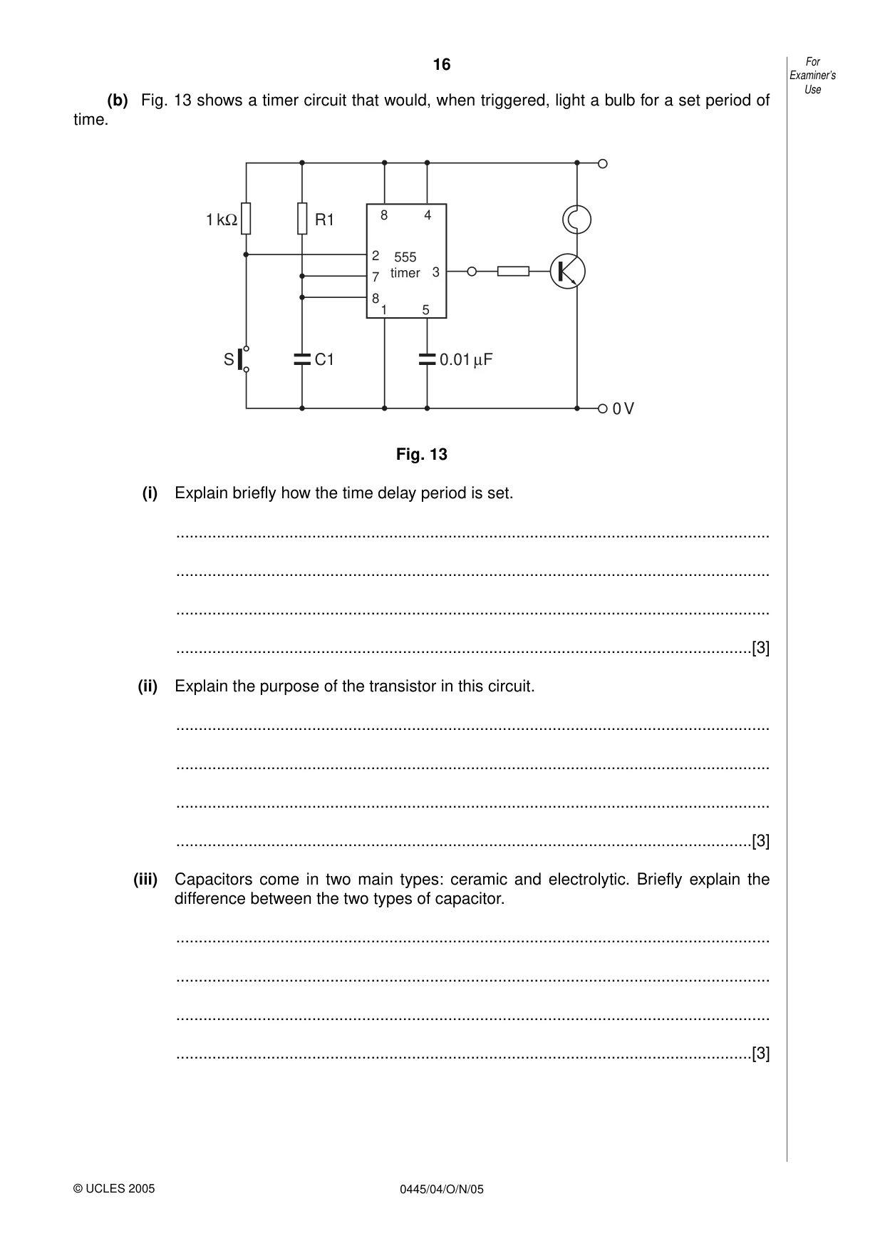
16 0445/04/O/N/05 (b) Fig. 13 shows a timer circuit that would, when triggered, light a bulb for a set period of time. Fig. 13 (i) Explain briefly how the time delay period is set. … … … …[3] (ii) Explain the purpose of the transistor in this circuit. … … … …[3] (iii) Capacitors come in two main types: ceramic and electrolytic. Briefly explain the difference between the two types of capacitor. … … … …[3] S C1 0 V R1 1 kΩ 0.01 µF 2 7 3 8 8 4 1 5 555 timer For Examiner’s Use © UCLES 2005
Question paper, page 17
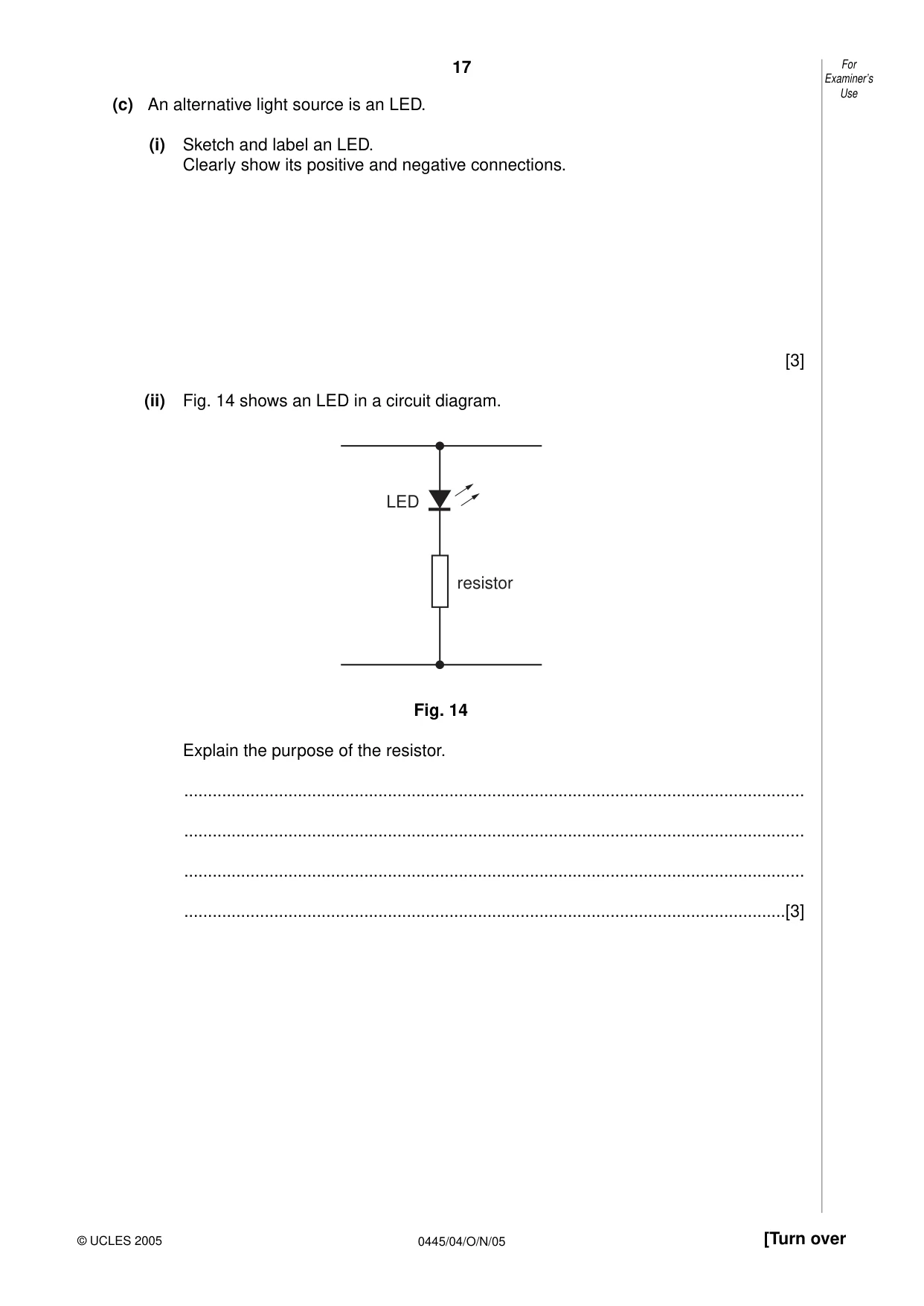
17 0445/04/O/N/05 [Turn over (c) An alternative light source is an LED. (i) Sketch and label an LED. Clearly show its positive and negative connections. [3] (ii) Fig. 14 shows an LED in a circuit diagram. Fig. 14 Explain the purpose of the resistor. … … … …[3] resistor LED For Examiner’s Use © UCLES 2005
Question paper, page 18
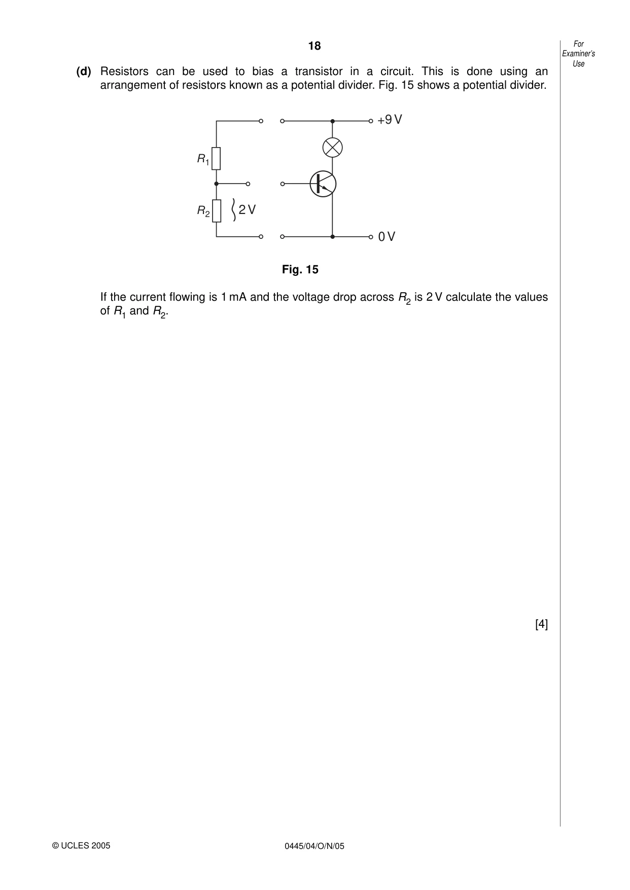
18 0445/04/O/N/05 (d) Resistors can be used to bias a transistor in a circuit. This is done using an arrangement of resistors known as a potential divider. Fig. 15 shows a potential divider. Fig. 15 If the current flowing is 1 mA and the voltage drop across R2 is 2 V calculate the values of R1 and R2. [4] +9 V 0 V 2 V R1 R2 For Examiner’s Use © UCLES 2005
Question paper, page 20
20 0445/04/O/N/05 BLANK PAGE Permission to reproduce items where third-party owned material protected by copyright is included has been sought and cleared where possible. Every reasonable effort has been made by the publisher (UCLES) to trace copyright holders, but if any items requiring clearance have unwittingly been included, the publisher will be pleased to make amends at the earliest possible opportunity. University of Cambridge International Examinations is part of the University of Cambridge Local Examinations Syndicate (UCLES), which is itself a department of the University of Cambridge.
Mark scheme, page 1
UNIVERSITY OF CAMBRIDGE INTERNATIONAL EXAMINATIONS International General Certificate of Secondary Education MARK SCHEME for the November 2005 question paper 0445 DESIGN AND TECHNOLOGY 0445/04 Paper 4 maximum raw mark 60 This mark scheme is published as an aid to teachers and students, to indicate the requirements of the examination. It shows the basis on which Examiners were initially instructed to award marks. It does not indicate the details of the discussions that took place at an Examiners’ meeting before marking began. Any substantial changes to the mark scheme that arose from these discussions will be recorded in the published Report on the Examination. All Examiners are instructed that alternative correct answers and unexpected approaches in candidates’ scripts must be given marks that fairly reflect the relevant knowledge and skills demonstrated. Mark schemes must be read in conjunction with the question papers and the Report on the Examination. The minimum marks in these components needed for various grades were previously published with these mark schemes, but are now instead included in the Report on the Examination for this session. • CIE will not enter into discussion or correspondence in connection with these mark schemes. CIE is publishing the mark schemes for the November 2005 question papers for most IGCSE and GCE Advanced Level and Advanced Subsidiary Level syllabuses and some Ordinary Level syllabuses. www.XtremePapers.com
Mark scheme, page 2
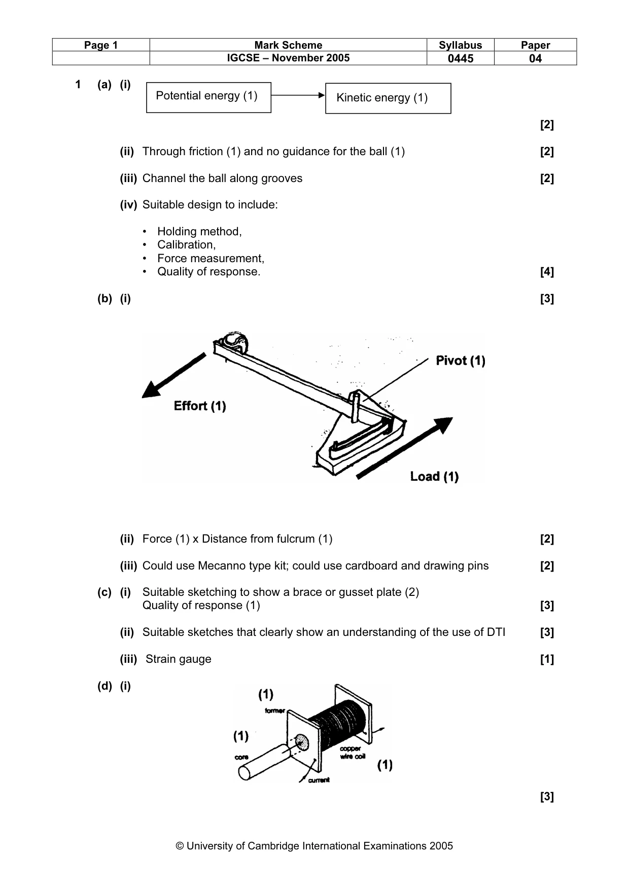
Page 1 Mark Scheme Syllabus Paper IGCSE – November 2005 0445 04 © University of Cambridge International Examinations 2005 1 (a) (i) [2] (ii) Through friction (1) and no guidance for the ball (1) [2] (iii) Channel the ball along grooves [2] (iv) Suitable design to include: • Holding method, • Calibration, • Force measurement, • Quality of response. [4] (b) (i) [3] (ii) Force (1) x Distance from fulcrum (1) [2] (iii) Could use Mecanno type kit; could use cardboard and drawing pins [2] (c) (i) Suitable sketching to show a brace or gusset plate (2) Quality of response (1) [3] (ii) Suitable sketches that clearly show an understanding of the use of DTI [3] (iii) Strain gauge [1] (d) (i) [3] Potential energy (1) Kinetic energy (1)
Mark scheme, page 3
Page 2 Mark Scheme Syllabus Paper IGCSE – November 2005 0445 04 © University of Cambridge International Examinations 2005 fixed pivot fixed pivot loose pivots guide (ii) Light Dependant Resistor (LDR) [1] (iii) To prevent back emf (1) damage (1) to the transistor [2] 2 (a) (i) [5] (ii) Linear (1); Rotation (1); Oscillation (1) [3] (iii) Mecanno; Fischer Technik; Card and paper fasteners [2] (b) (i) Cam [1] (ii) A row of cam (1) with each one having its centre set at different positions on the shaft (1) triggers the switches at different time for on rotation of the shaft (1) [3] (iii) Pulley wheel [1] (iv) Worm gear [1] (v) Quiet; no slip [2] (c) (i) (1) [3] (ii) (1) [4] pivot pivot yokes pivot centre member
Mark scheme, page 4
Page 3 Mark Scheme Syllabus Paper IGCSE – November 2005 0445 04 © University of Cambridge International Examinations 2005 (iii) Bearing Diagram Application Plain Journal Bearing Low speed shaft support Ball bearing (1) Washing machine drum Roller bearing Heavy radial loads at low speeds [4] (iv) Reduce friction; reduce wear; reduce heat [1] 3 Structures can be classified in to two main types Type of structure Example Application Framework Bridge [1] Shell [1] Car body [1] (b) (i) The effect of impact (1) can cause a structure to fail (1). It increases the moment (1) of the applied force. [3] (ii) Benefit: Quick and easy to build up a structure [2] Drawback: Tend to buckle easily [2] (iii) plain bearing or bush A lashed joint radial load oil hole bearing support shaft
Mark scheme, page 5
Page 4 Mark Scheme Syllabus Paper IGCSE – November 2005 0445 04 © University of Cambridge International Examinations 2005 (c) (i) [3] (ii) 6Nm [3] (d) (i) Moments @ R1 10 x 0.75 = 3 x R2 (1) 7.5/3 = R2 (1) = 2.5 N (1) For equilibrium R1 + R2 = 10 N thus R1 = 10 N − 2.5 N = 7.5 N (1) [4] (ii) [6] 4 (a) (i) [5] Switches in parallel Light bulb
Mark scheme, page 6
Page 5 Mark Scheme Syllabus Paper IGCSE – November 2005 0445 04 © University of Cambridge International Examinations 2005 (ii) [5] (iii) Toggle switch; slider switch [1] (b) (i) The resistor RI and capacitor CI act together (1) to create a delay (1) which can be varied according to their values (1). [3] (ii) The transistor acts as a sensitive switch (1) to control the current flow (1) through the bulb (1). [3] (iii) Electrolytic capacitors have polarity (1) and must be connected accordingly (1). Ceramic capacitors are usually small value capacitors and can be connected either way round (1) [3] (c) (i) [3] (ii) The resistor is a current limiting device (1) that will protect the LED (1) from overload (1) [3] (d) Total Resistance = V/I = 9/0.001 = 9000 Ω (1) R2 = V2/1 = 2/0.001 = 2000 Ω (1) Thus R1 + R2 = 9000 (1) and R1 = 9000 −2000 = 7000 (1) [4] the negative (cathode) of the LED is always on the side with the flat edge Light bulb Switches in series resistor