Cambridge A Level Physics 9702 — 2013 Oct/Nov Paper 2 · Variant 3
9702/23/O/N/13 · 7 questions · 60 marks · ≈68 min
The question paper and its mark scheme, free to read here and free to download. This is Cambridge’s own paper, exactly as it was sat.
Question paper16 pages
Mark scheme4 pages
Answers below. Sit the paper first if you are practising.

Questions as text
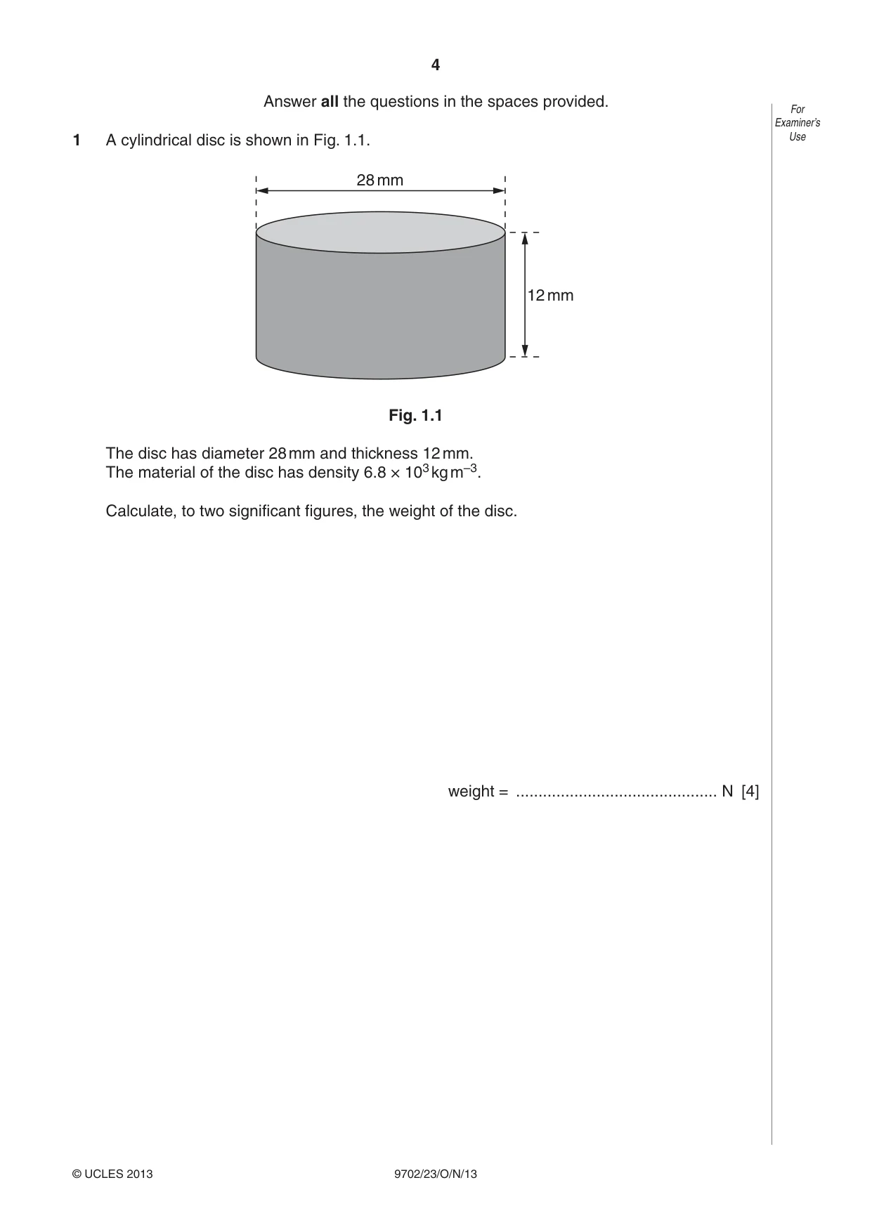
Q1 · A cylindrical disc is shown in Fig
1 A cylindrical disc is shown in Fig. 1.1. Use 28 mm 12 mm Fig. 1.1 The disc has diameter 28 mm and thickness 12 mm. The material of the disc has density 6.8 × 10³ kg m–3. Calculate, to two significant figures, the weight of the disc. weight = ............................................. N [4]
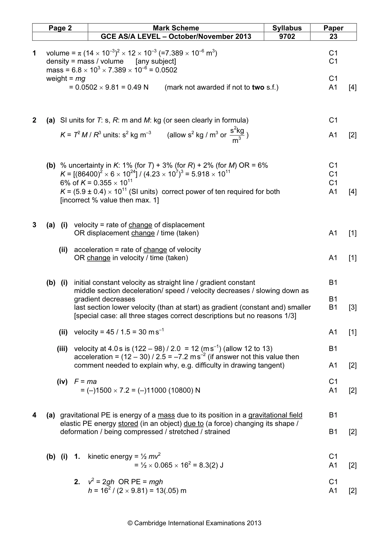
Mark scheme: 1 volume = π (14 × 10–3)2 × 12 × 10–3 (=7.389 × 10⁻⁶ m3) C1 density = mass / volume [any subject] C1 mass = 6.8 × 103 × 7.389 × 10–6 = 0.0502 weight = mg C1 weight = 0.0502 × 9.81 = 0.49 N (mark not awarded if not to two s.f.) A1 [4]
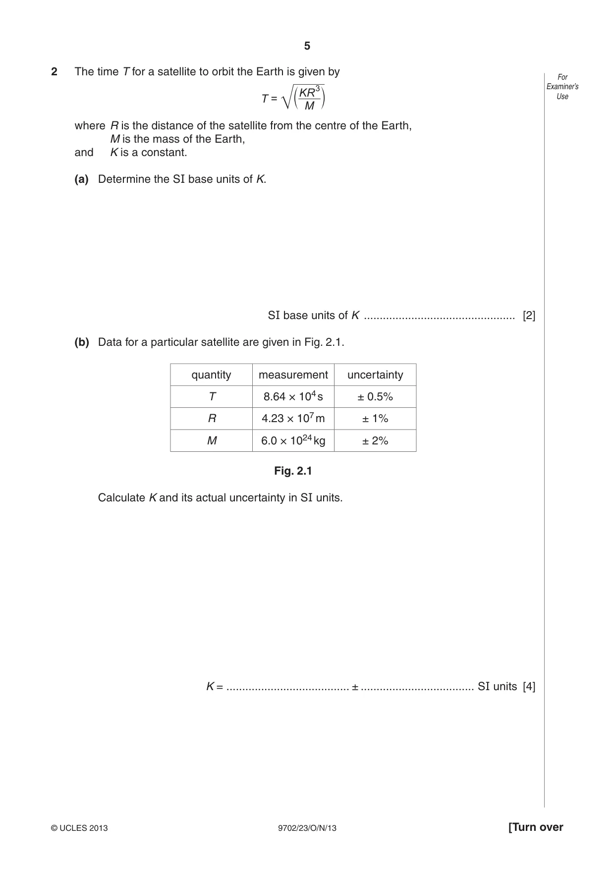
Q2 · The time T for a satellite to orbit the Earth is given by For KR3 Examiner’sUse T = c m M…
2 The time T for a satellite to orbit the Earth is given by For KR3 Examiner’sUse T = c m M where R is the distance of the satellite from the centre of the Earth, M is the mass of the Earth, and K is a constant. (a) Determine the SI base units of K. SI base units of K ................................................ [2] (b) Data for a particular satellite are given in Fig. 2.1. quantity measurement uncertainty T 8.64 × 10⁴ s ± 0.5% R 4.23 × 10⁷ m ± 1% M 6.0 × 1024 kg ± 2% Fig. 2.1 Calculate K and its actual uncertainty in SI units. K = ....................................... ± .................................... SI units [4]
Mark scheme: 2 (a) SI units for T: s, R: m and M: kg (or seen clearly in formula) C1 s 2kg K = T2 M / R3 units: s2 kg m–3 (allow s2 kg / m3 or 3 ) A1 [2] m (b) % uncertainty in K: 1% (for T) + 3% (for R) + 2% (for M) OR = 6% C1 K = [(86400)2 × 6 × 1024] / (4.23 × 10⁷)3 = 5.918 × 10¹¹ C1 6% of K = 0.355 × 10¹¹ C1 K = (5.9 ± 0.4) × 1011 (SI units) correct power of ten required for both A1 [4] [incorrect % value then max. 1]
Q3 · Define For Examiner’s (i) velocity, Use…
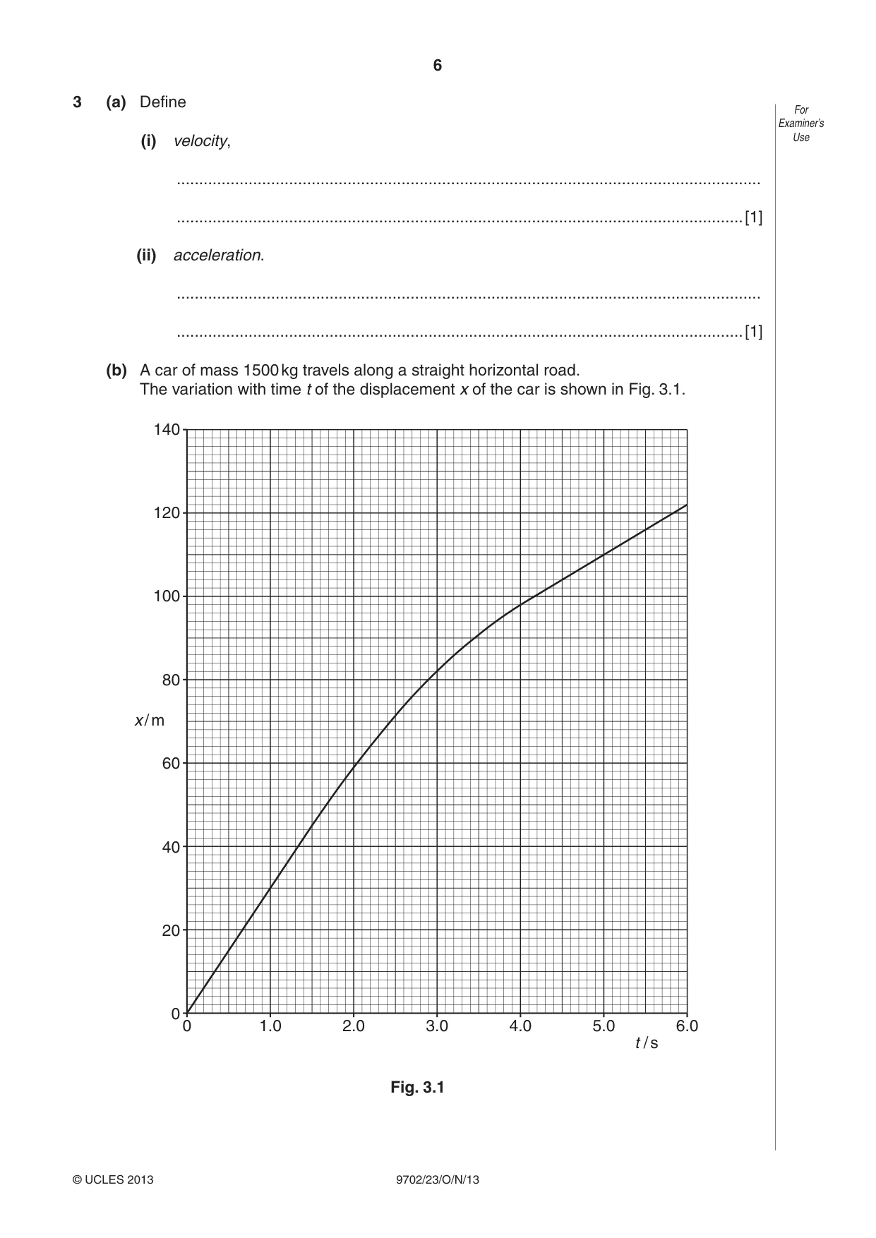
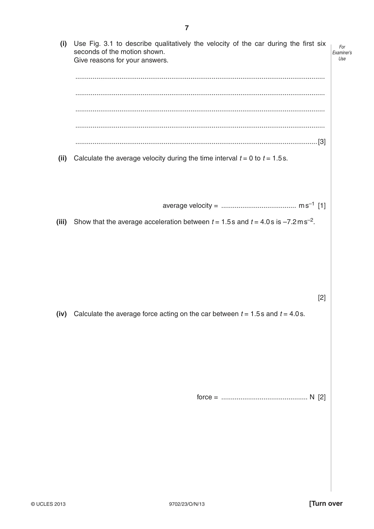
3 (a) Define For Examiner’s (i) velocity, Use .................................................................................................................................. ..............................................................................................................................[1] (ii) acceleration. .................................................................................................................................. ..............................................................................................................................[1] (b) A car of mass 1500 kg travels along a straight horizontal road. The variation with time t of the displacement x of the car is shown in Fig. 3.1. 140 120 100 80 x / m 60 40 20 0 0 1.0 2.0 3.0 4.0 5.0 6.0 t / s Fig. 3.1 (i) Use Fig. 3.1 to describe qualitatively the velocity of the car during the first six For seconds of the motion shown. Examiner’s Give reasons for your answers. Use .................................................................................................................................. .................................................................................................................................. .................................................................................................................................. .................................................................................................................................. ..............................................................................................................................[3] (ii) Calculate the average velocity during the time interval t = 0 to t = 1.5 s. average velocity = ....................................... m s–1 [1] (iii) Show that the average acceleration between t = 1.5 s and t = 4.0 s is –7.2 m s–2. [2] (iv) Calculate the average force acting on the car between t = 1.5 s and t = 4.0 s. force = ............................................. N [2]
Mark scheme: 3 (a) (i) velocity = rate of change of displacement OR displacement change / time (taken) A1 [1] (ii) acceleration = rate of change of velocity OR change in velocity / time (taken) A1 [1] (b) (i) initial constant velocity as straight line / gradient constant B1 middle section deceleration/ speed / velocity decreases / slowing down as gradient decreases B1 last section lower velocity (than at start) as gradient (constant and) smaller B1 [3] [special case: all three stages correct descriptions but no reasons 1/3] (ii) velocity = 45 / 1.5 = 30 m s–1 A1 [1] (iii) velocity at 4.0 s is (122 – 98) / 2.0 = 12 (m s–1) (allow 12 to 13) B1 acceleration = (12 – 30) / 2.5 = –7.2 m s–2 (if answer not this value then comment needed to explain why, e.g. difficulty in drawing tangent) A1 [2] (iv) F = ma C1 F = (–)1500 × 7.2 = (–)11000 (10800) N A1 [2]
Q4 · Distinguish between gravitational potential energy and elastic potential energy
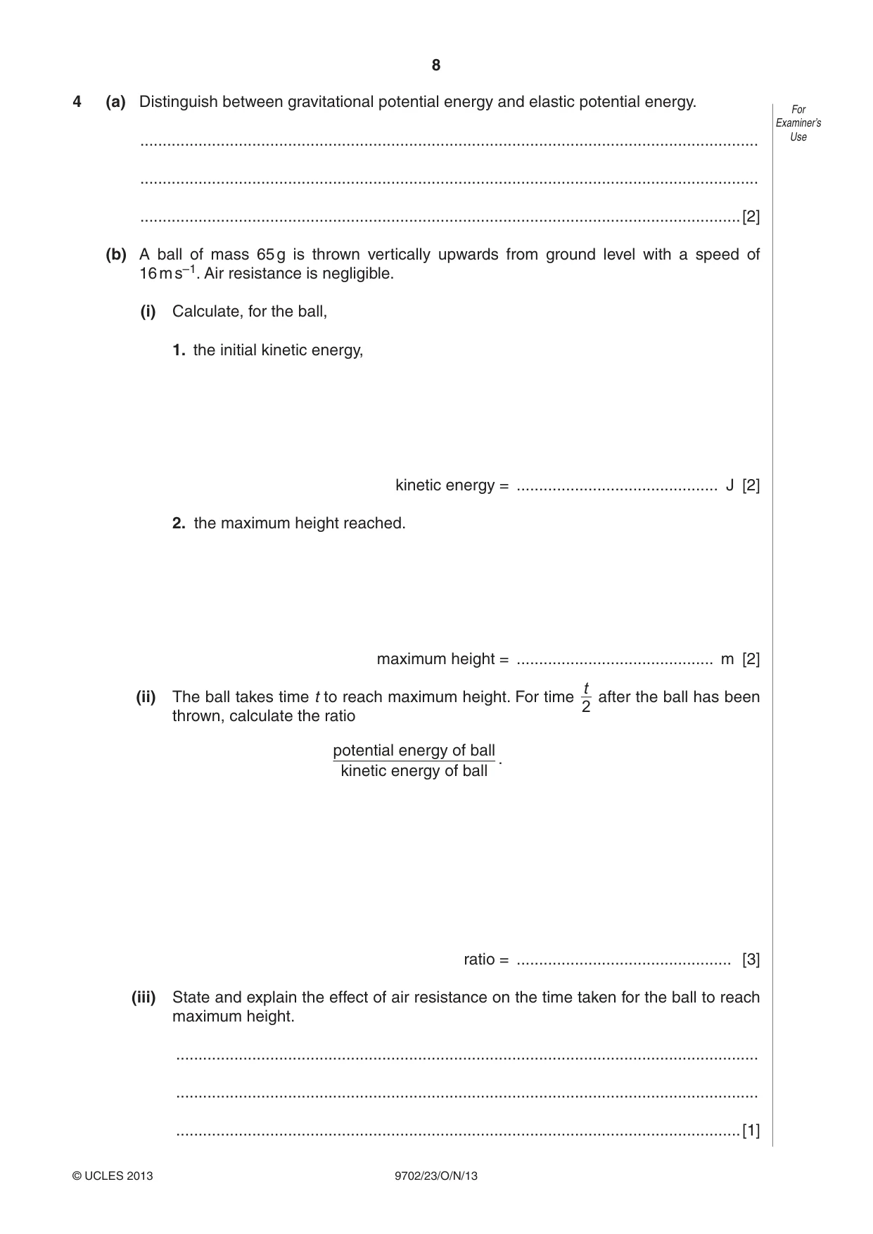
4 (a) Distinguish between gravitational potential energy and elastic potential energy. For Examiner’s .......................................................................................................................................... Use .......................................................................................................................................... ......................................................................................................................................[2] (b) A ball of mass 65 g is thrown vertically upwards from ground level with a speed of 16 m s–1. Air resistance is negligible. (i) Calculate, for the ball, 1. the initial kinetic energy, kinetic energy = ............................................. J [2] 2. the maximum height reached. maximum height = ............................................ m [2] t (ii) The ball takes time t to reach maximum height. For time after the ball has been 2 thrown, calculate the ratio potential energy of ball . kinetic energy of ball ratio = ................................................ [3] (iii) State and explain the effect of air resistance on the time taken for the ball to reach maximum height. .................................................................................................................................. .................................................................................................................................. ..............................................................................................................................[1]
Mark scheme: 4 (a) gravitational PE is energy of a mass due to its position in a gravitational field B1 elastic PE energy stored (in an object) due to (a force) changing its shape / deformation / being compressed / stretched / strained B1 [2] (b) (i) 1. kinetic energy = ½ mv2 C1 kinetic energy = ½ × 0.065 × 162 = 8.3(2) J A1 [2] 2. v2 = 2gh OR PE = mgh C1 h = 162 / (2 × 9.81) = 13(.05) m A1 [2] GCE AS/A LEVEL – October/November 2013 9702 23 (ii) speed at t = ½ total time = 8 (m s–1) or total t =1.63 or t1/2 = 0.815 s C1 KE is ¼ or h at t1/2 = 9.78 (m) C1 and PE is ¾ of max ratio = 3 or ratio = 9.78 / 3.26 = 3 A1 [3] (iii) time is less because (average) acceleration is greater OR average force is greater B1 [1]
More questions on Gravitational potential energy and kinetic energy
Q5 · Define, for a wave, For Examiner’s 1
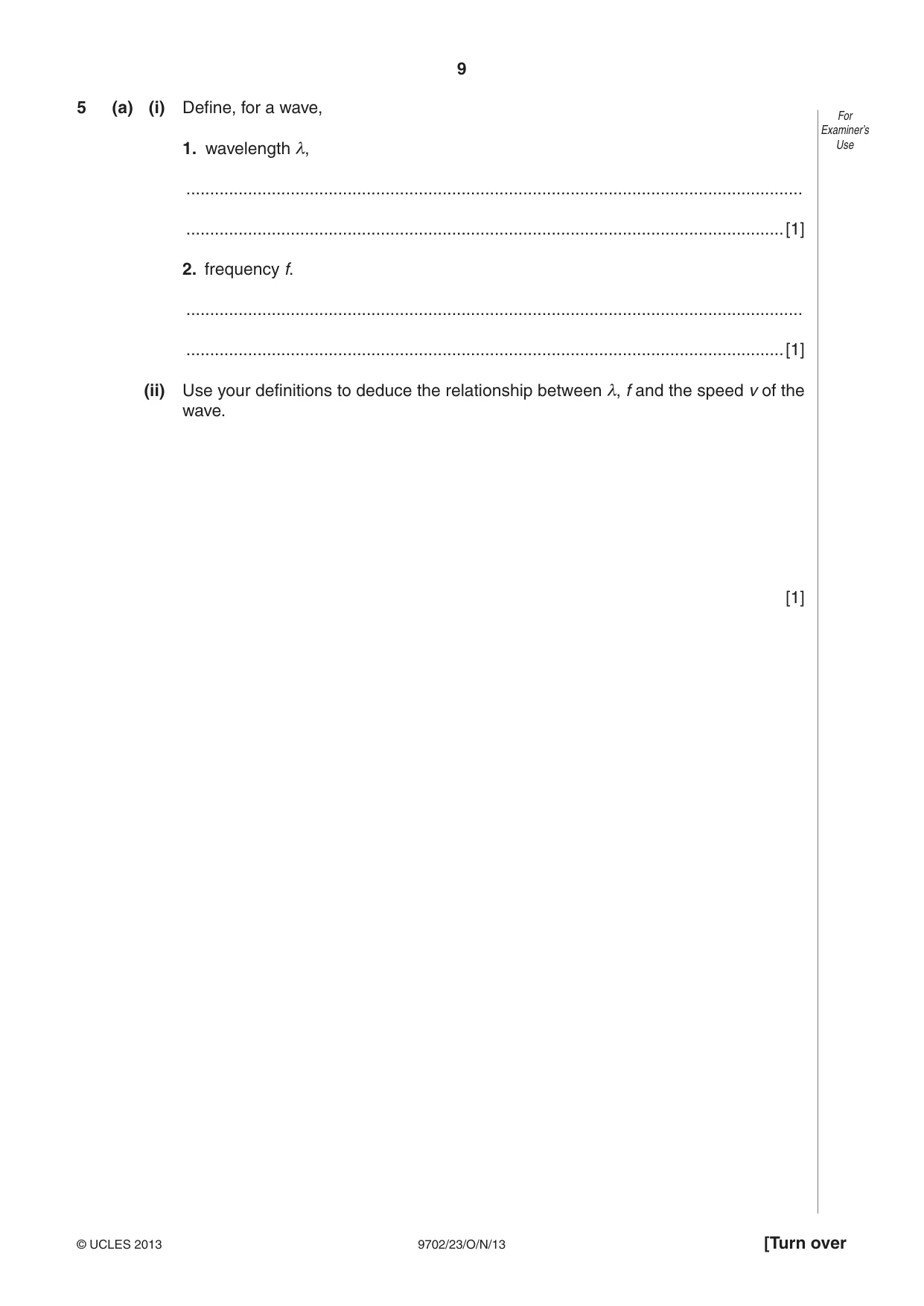
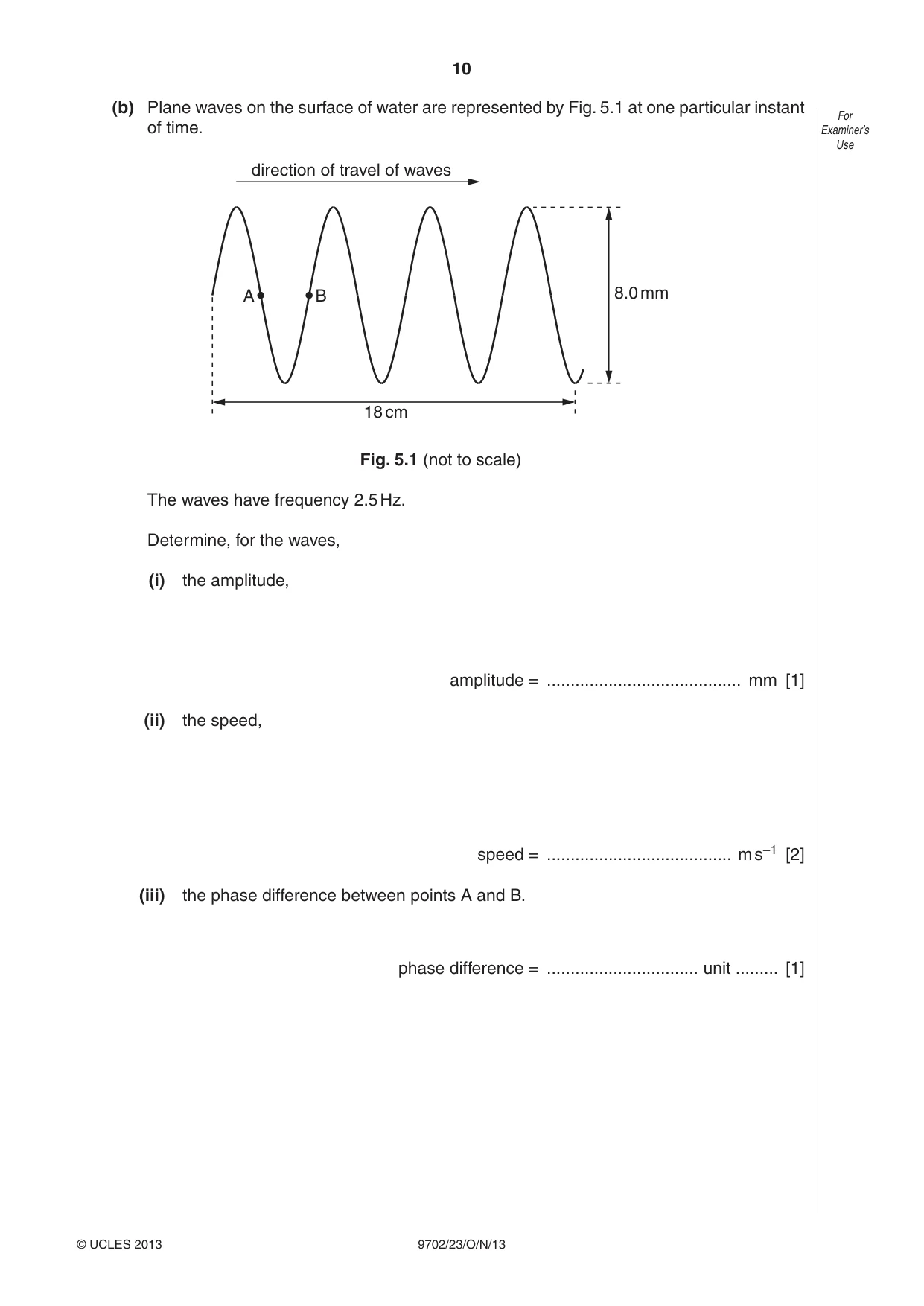
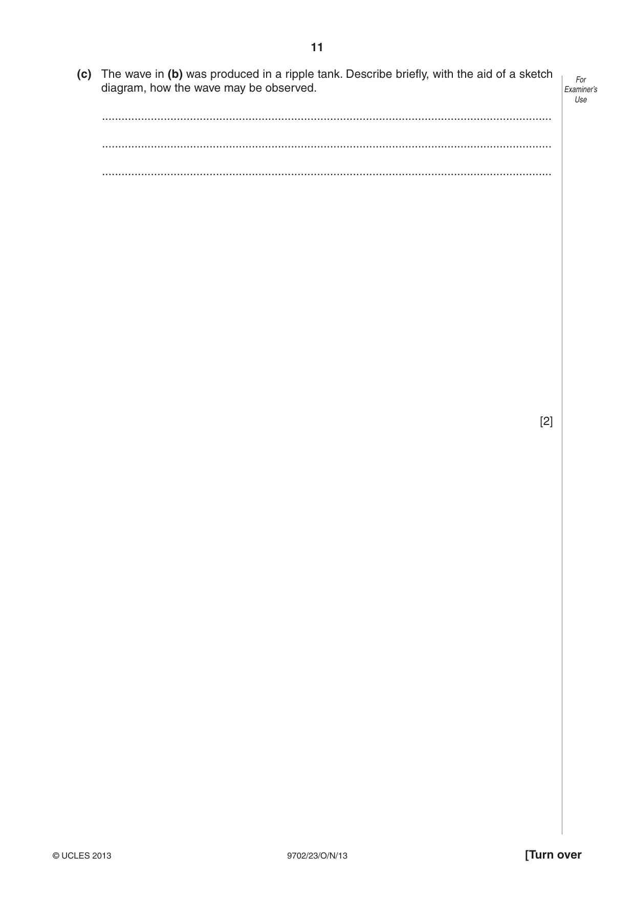
5 (a) (i) Define, for a wave, For Examiner’s 1. wavelength λ, Use .................................................................................................................................. ..............................................................................................................................[1] 2. frequency f. .................................................................................................................................. ..............................................................................................................................[1] (ii) Use your definitions to deduce the relationship between λ, f and the speed v of the wave. [1] (b) Plane waves on the surface of water are represented by Fig. 5.1 at one particular instant For of time. Examiner’s Use direction of travel of waves A B 8.0 mm 18 cm Fig. 5.1 (not to scale) The waves have frequency 2.5 Hz. Determine, for the waves, (i) the amplitude, amplitude = ......................................... mm [1] (ii) the speed, speed = ....................................... m s–1 [2] (iii) the phase difference between points A and B. phase difference = ................................ unit ......... [1] (c) The wave in (b) was produced in a ripple tank. Describe briefly, with the aid of a sketch For diagram, how the wave may be observed. Examiner’s Use .......................................................................................................................................... .......................................................................................................................................... .......................................................................................................................................... [2]
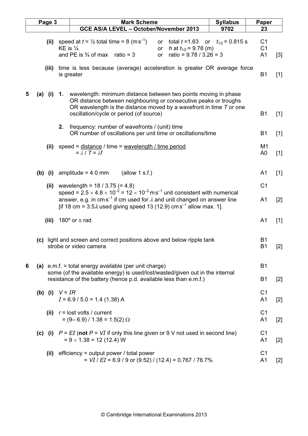
Mark scheme: 5 (a) (i) 1. wavelength: minimum distance between two points moving in phase OR distance between neighbouring or consecutive peaks or troughs OR wavelength is the distance moved by a wavefront in time T or one oscillation/cycle or period (of source) B1 [1] 2. frequency: number of wavefronts / (unit) time OR number of oscillations per unit time or oscillations/time B1 [1] (ii) speed = distance / time = wavelength / time period M1 speed = λ / T = λf A0 [1] (b) (i) amplitude = 4.0 mm (allow 1 s.f.) A1 [1] (ii) wavelength = 18 / 3.75 (= 4.8) C1 speed = 2.5 × 4.8 × 10–2 = 12 × 10–2 m s–1 unit consistent with numerical answer, e.g. in cm s–1 if cm used for λ and unit changed on answer line A1 [2] [if 18 cm = 3.5λ used giving speed 13 (12.9) cm s–1 allow max. 1]. (iii) 180º or π rad A1 [1] (c) light and screen and correct positions above and below ripple tank B1 strobe or video camera B1 [2]
Q6 · A battery connected in series with a resistor R of resistance 5.0 Ω is shown in Fig
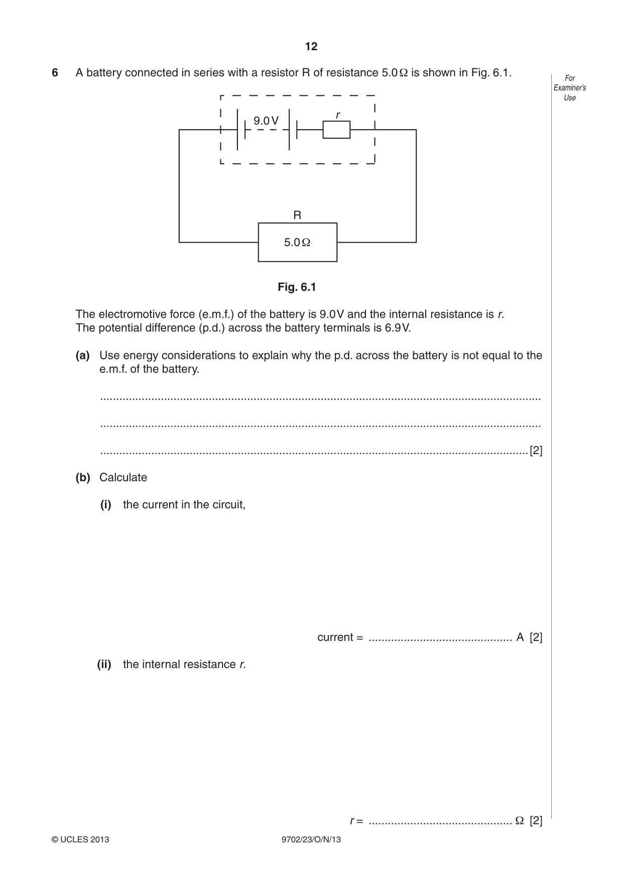
6 A battery connected in series with a resistor R of resistance 5.0 Ω is shown in Fig. 6.1. For Examiner’s Use r 9.0 V R 5.0 Ω Fig. 6.1 The electromotive force (e.m.f.) of the battery is 9.0 V and the internal resistance is r. The potential difference (p.d.) across the battery terminals is 6.9 V. (a) Use energy considerations to explain why the p.d. across the battery is not equal to the e.m.f. of the battery. .......................................................................................................................................... .......................................................................................................................................... ......................................................................................................................................[2] (b) Calculate (i) the current in the circuit, current = ............................................. A [2] (ii) the internal resistance r. r = ............................................. Ω [2] (c) Calculate, for the battery in the circuit, For Examiner’s (i) the total power produced, Use power = ............................................ W [2] (ii) the efficiency. efficiency = ................................................ [2]
Mark scheme: 6 (a) e.m.f. = total energy available (per unit charge) B1 some (of the available energy) is used/lost/wasted/given out in the internal resistance of the battery (hence p.d. available less than e.m.f.) B1 [2] (b) (i) V = IR C1 I = 6.9 / 5.0 = 1.4 (1.38) A A1 [2] (ii) r = lost volts / current C1 r = (9– 6.9) / 1.38 = 1.5(2) Ω A1 [2] (c) (i) P = EI (not P = VI if only this line given or 9 V not used in second line) C1 P = 9 × 1.38 = 12 (12.4) W A1 [2] (ii) efficiency = output power / total power C1 efficiency = VI / EI = 6.9 / 9 or (9.52) / (12.4) = 0.767 / 76.7% A1 [2] GCE AS/A LEVEL – October/November 2013 9702 23
Q7 · Two horizontal metal plates are connected to a power supply, as shown in Fig
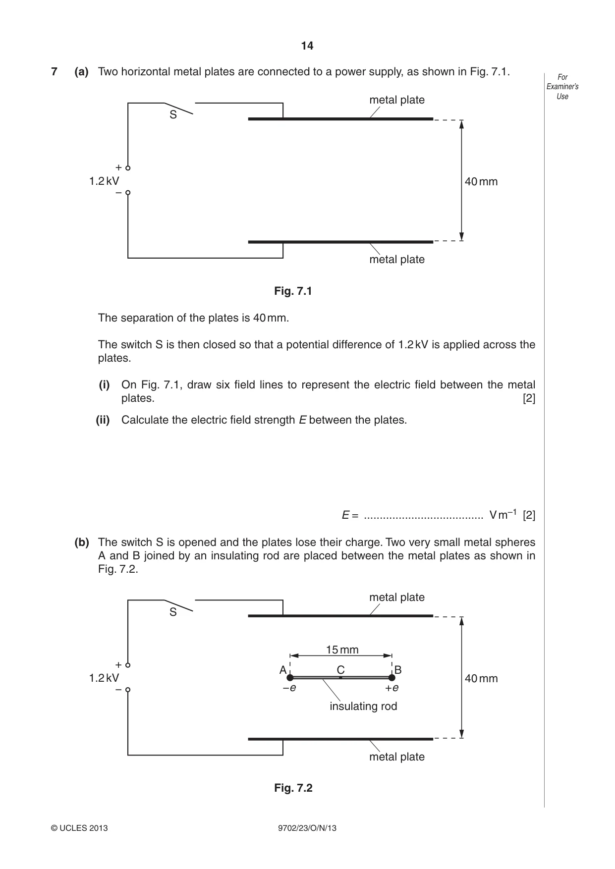
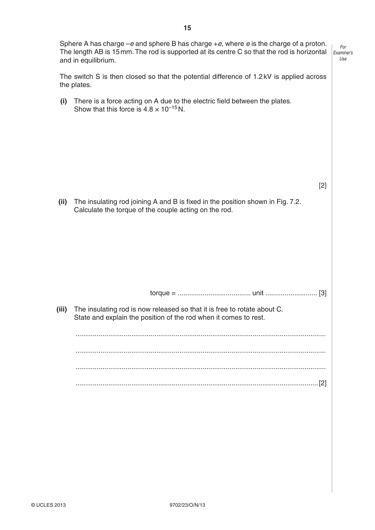
7 (a) Two horizontal metal plates are connected to a power supply, as shown in Fig. 7.1. For Examiner’s metal plate Use S + 1.2 kV 40 mm − metal plate Fig. 7.1 The separation of the plates is 40 mm. The switch S is then closed so that a potential difference of 1.2 kV is applied across the plates. (i) On Fig. 7.1, draw six field lines to represent the electric field between the metal plates. [2] (ii) Calculate the electric field strength E between the plates. E = ...................................... V m–1 [2] (b) The switch S is opened and the plates lose their charge. Two very small metal spheres A and B joined by an insulating rod are placed between the metal plates as shown in Fig. 7.2. metal plate S 15 mm + A C B 1.2 kV 40 mm − −e +e insulating rod metal plate Fig. 7.2 Sphere A has charge –e and sphere B has charge +e, where e is the charge of a proton. For The length AB is 15 mm. The rod is supported at its centre C so that the rod is horizontal Examiner’s and in equilibrium. Use The switch S is then closed so that the potential difference of 1.2 kV is applied across the plates. (i) There is a force acting on A due to the electric field between the plates. Show that this force is 4.8 × 10⁻¹⁵ N. [2] (ii) The insulating rod joining A and B is fixed in the position shown in Fig. 7.2. Calculate the torque of the couple acting on the rod. torque = ...................................... unit ........................... [3] (iii) The insulating rod is now released so that it is free to rotate about C. State and explain the position of the rod when it comes to rest. .................................................................................................................................. .................................................................................................................................. .................................................................................................................................. ..............................................................................................................................[2]
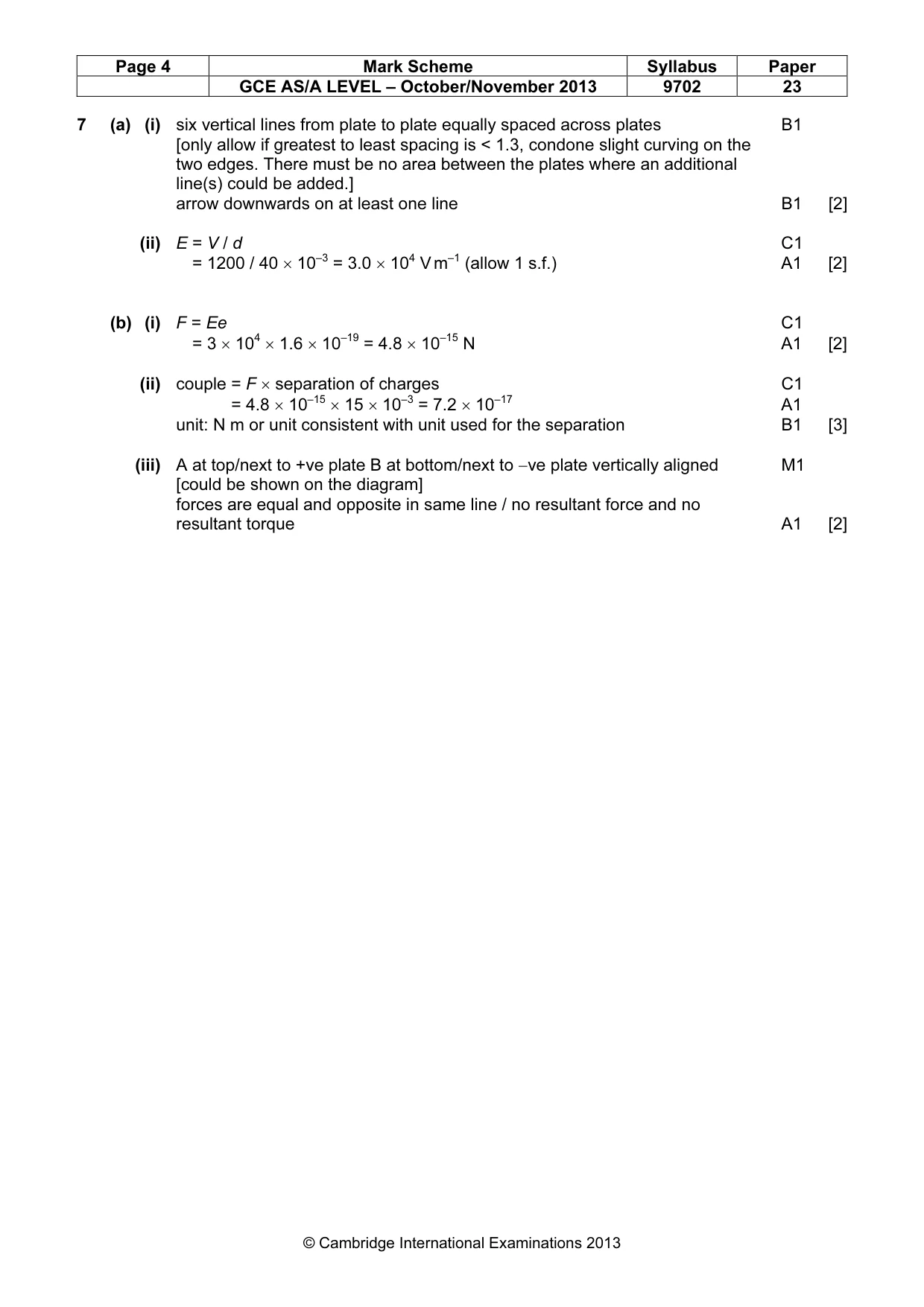
Mark scheme: 7 (a) (i) six vertical lines from plate to plate equally spaced across plates B1 [only allow if greatest to least spacing is < 1.3, condone slight curving on the two edges. There must be no area between the plates where an additional line(s) could be added.] arrow downwards on at least one line B1 [2] (ii) E = V / d C1 E = 1200 / 40 × 10–3 = 3.0 × 10⁴ V m–1 (allow 1 s.f.) A1 [2] (b) (i) F = Ee C1 E = 3 × 104 × 1.6 × 10–19 = 4.8 × 10⁻¹⁵ N A1 [2] (ii) couple = F × separation of charges C1 couple = 4.8 × 10–15 × 15 × 10–3 = 7.2 × 10⁻¹⁷ A1 unit: N m or unit consistent with unit used for the separation B1 [3] (iii) A at top/next to +ve plate B at bottom/next to −ve plate vertically aligned M1 [could be shown on the diagram] forces are equal and opposite in same line / no resultant force and no resultant torque A1 [2]
What was in this paper
The subtopics covered by these 7 questions, and how many questions each got. Open one in a new tab to see every Cambridge question on it.
What you needed in this session
Cambridge’s own grade thresholds for 2013 Oct/Nov, Paper 2 · Variant 3. A higher threshold means an easier paper — the bar moves with how the cohort did.