Cambridge A Level Design and Technology 9705 — 2014 Oct/Nov Paper 1 · Variant 3
9705/13/O/N/14 · 120 marks · ≈135 min
The question paper and its mark scheme, free to read here and free to download. This is Cambridge’s own paper, exactly as it was sat.
Question paper16 pages
Mark scheme5 pages
Answers below. Sit the paper first if you are practising.
Paper as text
Question paper, page 1
This document consists of 13 printed pages and 3 blank pages. DC (RW/AR) 85704/3 © UCLES 2014 [Turn over Cambridge International Examinations Cambridge International Advanced Subsidiary and Advanced Level * 9 3 3 2 2 5 5 1 2 8 * DESIGN AND TECHNOLOGY 9705/13 Paper 1 October/November 2014 3 hours Additional Materials: Answer Booklet/A4 Paper A3 Drawing Paper (2 sheets) Extra sheets of A3 drawing paper for candidates who have used up both sides of their 2 sheets A range of design drawing equipment READ THESE INSTRUCTIONS FIRST If you have been given an Answer Booklet, follow the instructions on the front cover of the Booklet. Write your name, Centre number and candidate number on all the work you hand in. Write in dark blue or black pen. You may use an HB pencil, or coloured pencils/pens as appropriate, for any diagrams, graphs or rough working. Do not use staples, paper clips, glue or correction fluid. DO NOT WRITE IN ANY BARCODES. Section A Answer one question on the Answer Booklet/A4 Paper provided. Section B Answer one question on the Answer Booklet/A4 Paper provided. Section C Answer one question on plain A3 paper. Use both sides of the paper. You may request additional sheets of A3 paper, but only if you have used up both sides of each of the 2 sheets provided. You are advised to spend 30 minutes on each of Sections A and B and 2 hours on Section C. At the end of the examination, fasten all your work securely together. The number of marks is given in brackets [ ] at the end of each question or part question. All dimensions are in millimetres.
Question paper, page 2
2 9705/13/O/N/14 © UCLES 2014 BLANK PAGE
Question paper, page 3
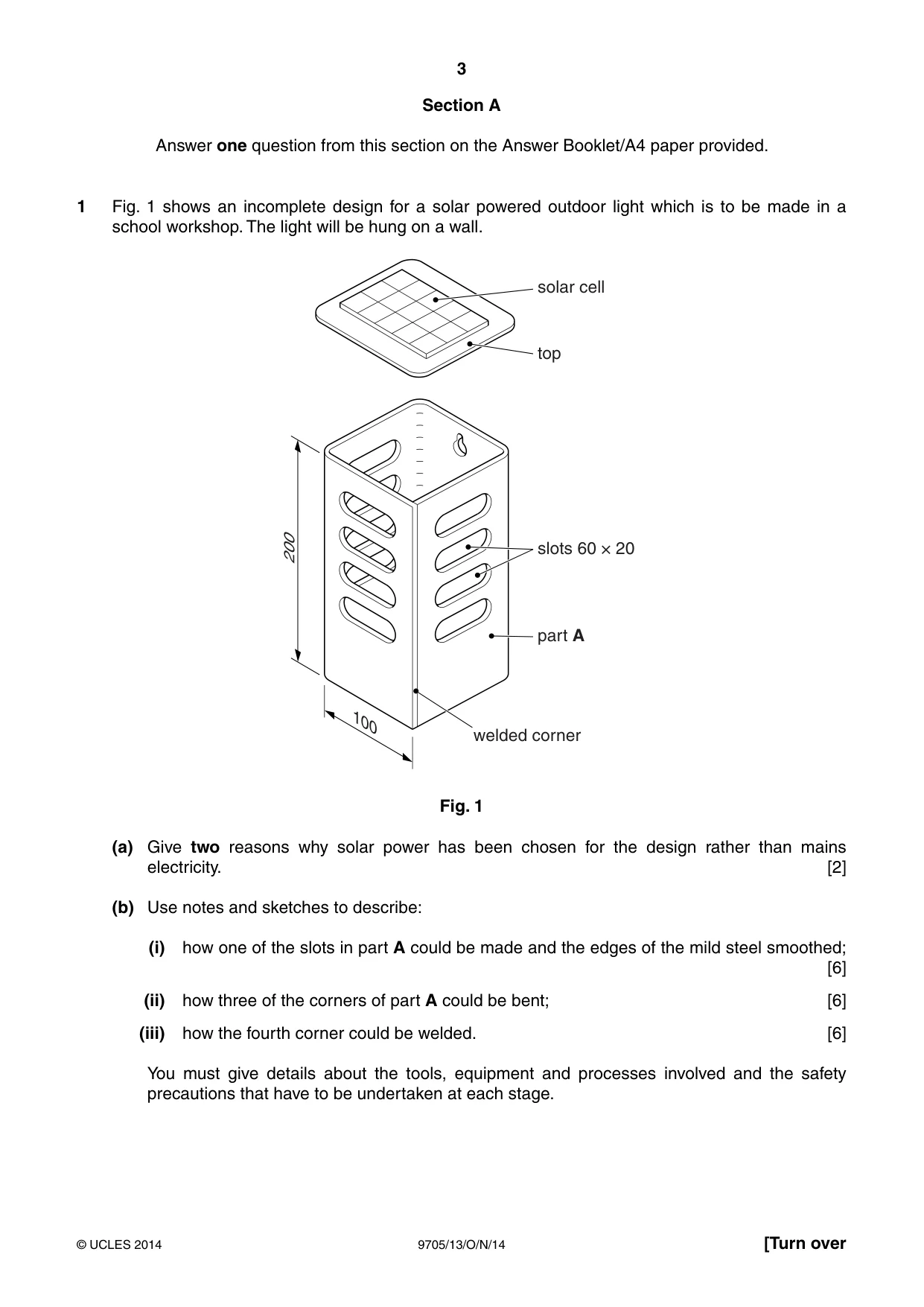
3 9705/13/O/N/14 © UCLES 2014 [Turn over Section A Answer one question from this section on the Answer Booklet/A4 paper provided. 1 Fig. 1 shows an incomplete design for a solar powered outdoor light which is to be made in a school workshop. The light will be hung on a wall. solar cell top slots 60 × 20 part A welded corner 100 200 Fig. 1 (a) Give two reasons why solar power has been chosen for the design rather than mains electricity. [2] (b) Use notes and sketches to describe: (i) how one of the slots in part A could be made and the edges of the mild steel smoothed; [6] (ii) how three of the corners of part A could be bent; [6] (iii) how the fourth corner could be welded. [6] You must give details about the tools, equipment and processes involved and the safety precautions that have to be undertaken at each stage.
Question paper, page 4
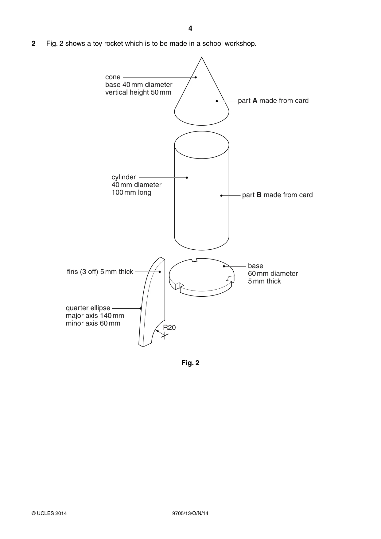
4 9705/13/O/N/14 © UCLES 2014 2 Fig. 2 shows a toy rocket which is to be made in a school workshop. part A made from card part B made from card base 60 mm diameter 5 mm thick quarter ellipse major axis 140 mm minor axis 60 mm cylinder 40 mm diameter 100 mm long cone base 40 mm diameter vertical height 50 mm fins (3 off) 5 mm thick R20 Fig. 2
Question paper, page 5
5 9705/13/O/N/14 © UCLES 2014 [Turn over (a) Name: (i) a suitable glue that could be used to join the pieces of card; [1] (ii) a suitable sheet material (other than card) that could be used to make the fins and the base. [1] (b) Use notes and sketches to describe: (i) how the two pieces of card required to make part A could be marked out, cut out and assembled; [6] (ii) how the three pieces of card required to make part B could be marked out, cut out and assembled; [6] (iii) how the three fins and the base could be marked out on a piece of sheet material 155 × 75 × 5; [3] (iv) how the base could be cut out. [3] You must give details about the tools, equipment and processes involved and the safety precautions that have to be undertaken at each stage.
Question paper, page 6
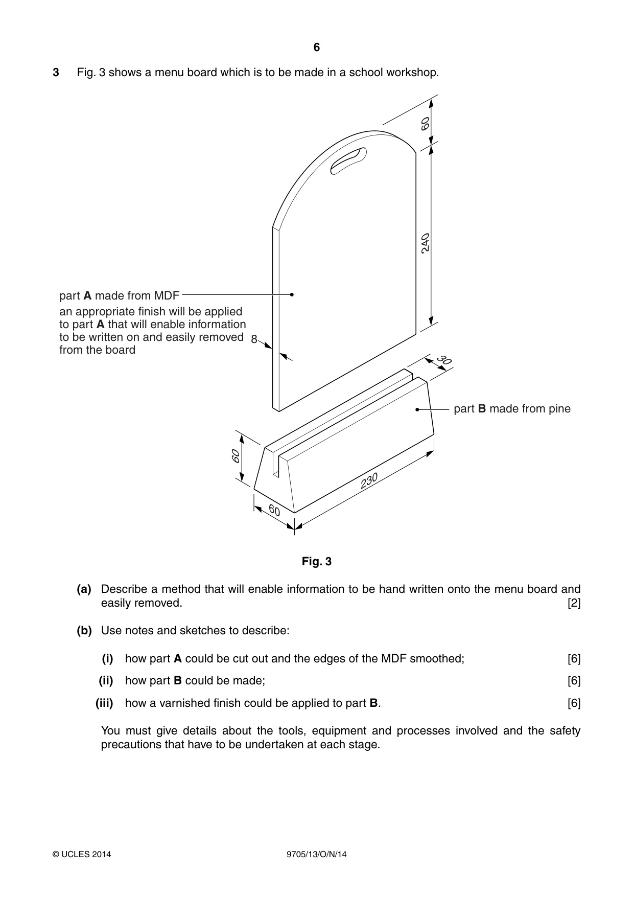
6 9705/13/O/N/14 © UCLES 2014 3 Fig. 3 shows a menu board which is to be made in a school workshop. part B made from pine part A made from MDF an appropriate finish will be applied to part A that will enable information to be written on and easily removed from the board 8 60 240 30 60 230 60 Fig. 3 (a) Describe a method that will enable information to be hand written onto the menu board and easily removed. [2] (b) Use notes and sketches to describe: (i) how part A could be cut out and the edges of the MDF smoothed; [6] (ii) how part B could be made; [6] (iii) how a varnished finish could be applied to part B. [6] You must give details about the tools, equipment and processes involved and the safety precautions that have to be undertaken at each stage.
Question paper, page 7
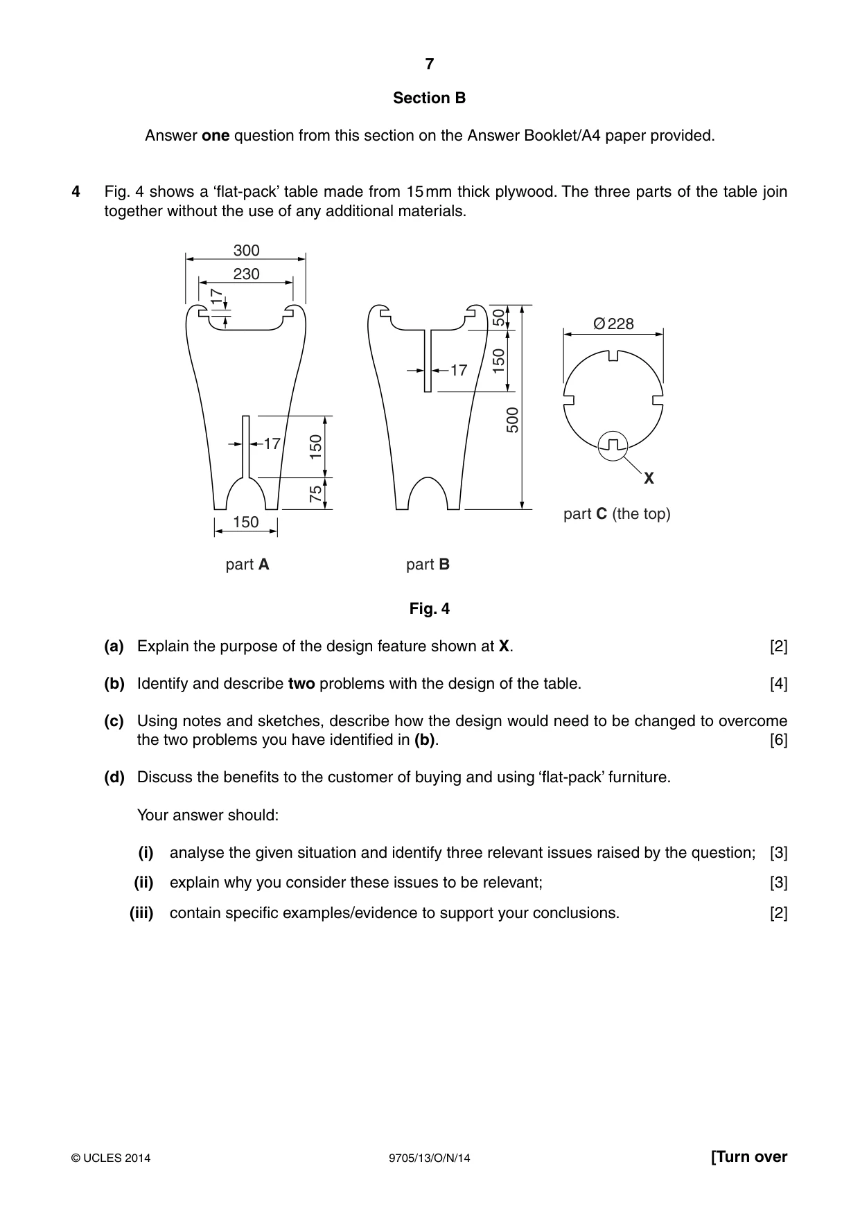
7 9705/13/O/N/14 © UCLES 2014 [Turn over Section B Answer one question from this section on the Answer Booklet/A4 paper provided. 4 Fig. 4 shows a ‘flat-pack’ table made from 15 mm thick plywood. The three parts of the table join together without the use of any additional materials. 300 230 17 Ø 228 X 17 150 500 150 50 75 17 150 part A part B part C (the top) Fig. 4 (a) Explain the purpose of the design feature shown at X. [2] (b) Identify and describe two problems with the design of the table. [4] (c) Using notes and sketches, describe how the design would need to be changed to overcome the two problems you have identified in (b). [6] (d) Discuss the benefits to the customer of buying and using ‘flat-pack’ furniture. Your answer should: (i) analyse the given situation and identify three relevant issues raised by the question; [3] (ii) explain why you consider these issues to be relevant; [3] (iii) contain specific examples/evidence to support your conclusions. [2]
Question paper, page 8
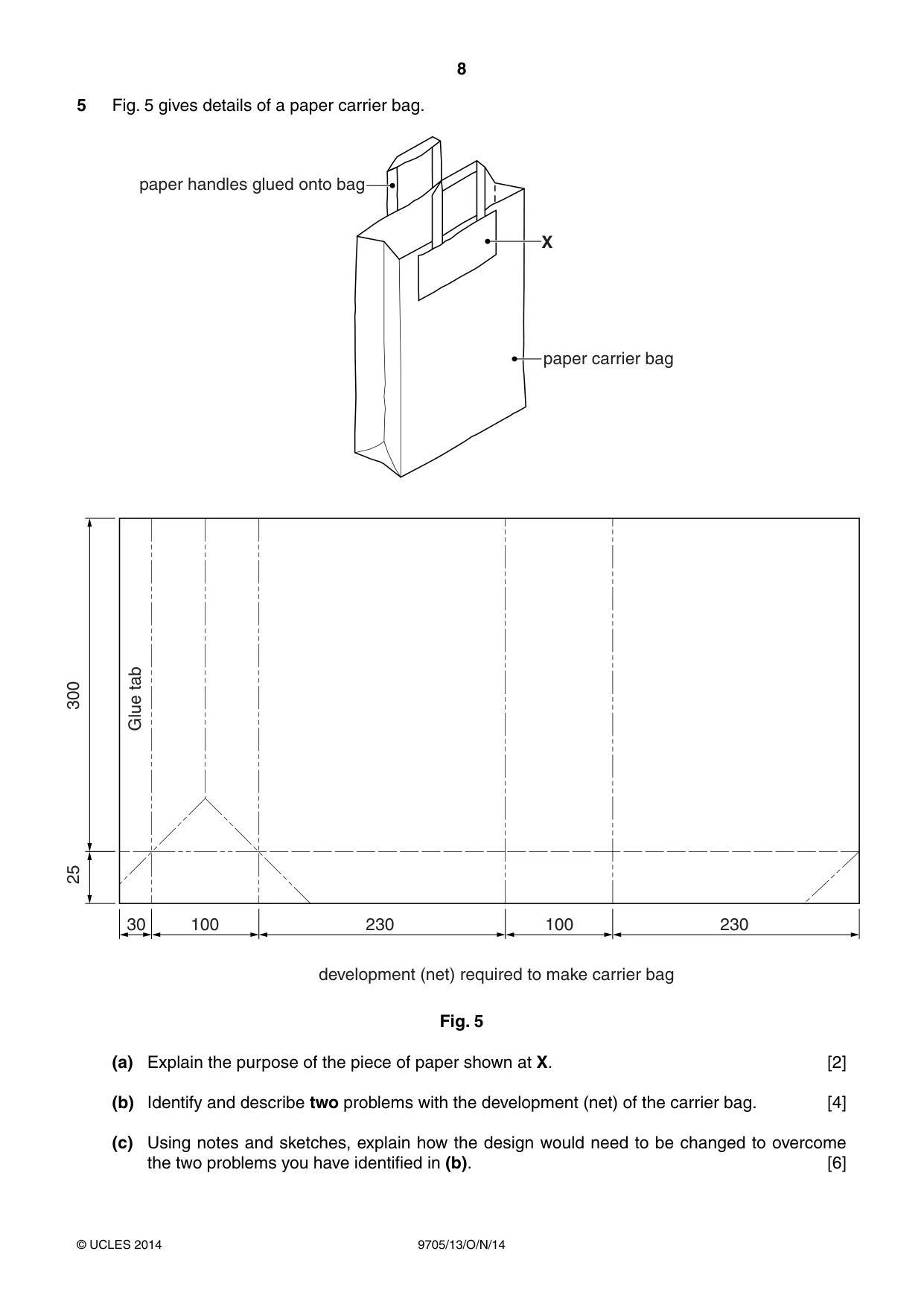
8 9705/13/O/N/14 © UCLES 2014 5 Fig. 5 gives details of a paper carrier bag. X paper carrier bag paper handles glued onto bag development (net) required to make carrier bag 25 300 30 100 230 100 230 Glue tab Fig. 5 (a) Explain the purpose of the piece of paper shown at X. [2] (b) Identify and describe two problems with the development (net) of the carrier bag. [4] (c) Using notes and sketches, explain how the design would need to be changed to overcome the two problems you have identified in (b). [6]
Question paper, page 9
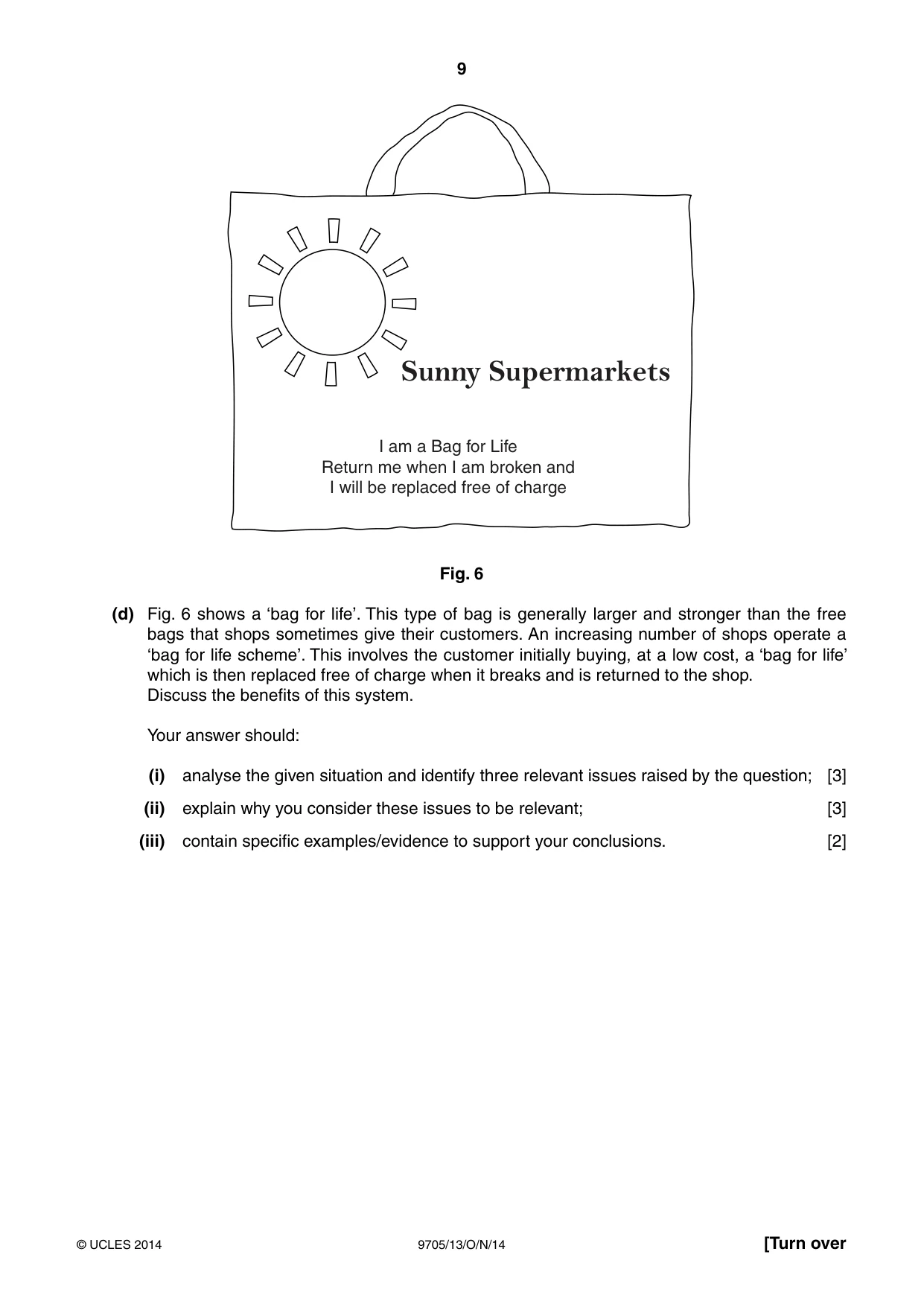
9 9705/13/O/N/14 © UCLES 2014 [Turn over Sunny Supermarkets I am a Bag for Life Return me when I am broken and I will be replaced free of charge Fig. 6 (d) Fig. 6 shows a ‘bag for life’. This type of bag is generally larger and stronger than the free bags that shops sometimes give their customers. An increasing number of shops operate a ‘bag for life scheme’. This involves the customer initially buying, at a low cost, a ‘bag for life’ which is then replaced free of charge when it breaks and is returned to the shop. Discuss the benefits of this system. Your answer should: (i) analyse the given situation and identify three relevant issues raised by the question; [3] (ii) explain why you consider these issues to be relevant; [3] (iii) contain specific examples/evidence to support your conclusions. [2]
Question paper, page 10
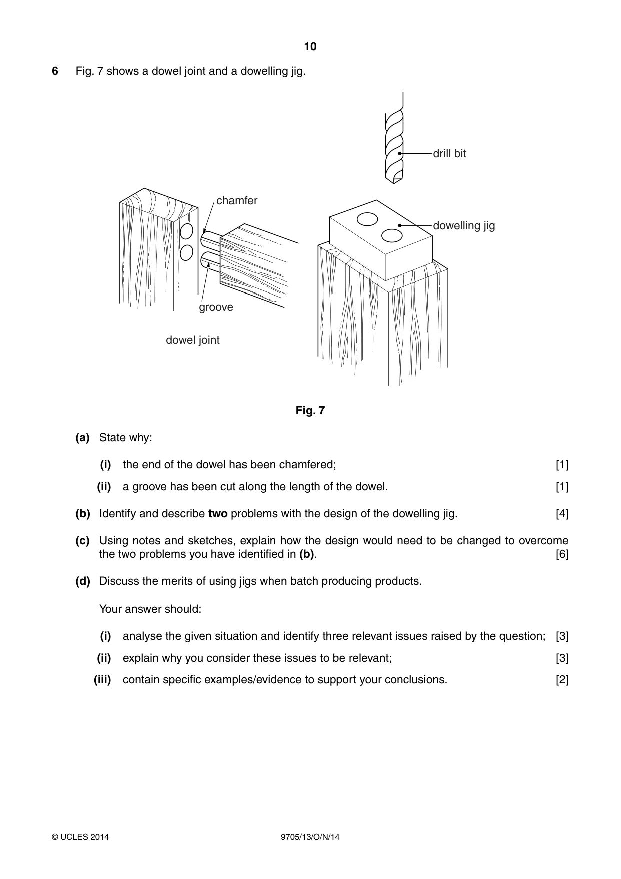
10 9705/13/O/N/14 © UCLES 2014 6 Fig. 7 shows a dowel joint and a dowelling jig. dowelling jig drill bit chamfer groove dowel joint Fig. 7 (a) State why: (i) the end of the dowel has been chamfered; [1] (ii) a groove has been cut along the length of the dowel. [1] (b) Identify and describe two problems with the design of the dowelling jig. [4] (c) Using notes and sketches, explain how the design would need to be changed to overcome the two problems you have identified in (b). [6] (d) Discuss the merits of using jigs when batch producing products. Your answer should: (i) analyse the given situation and identify three relevant issues raised by the question; [3] (ii) explain why you consider these issues to be relevant; [3] (iii) contain specific examples/evidence to support your conclusions. [2]
Question paper, page 11
11 9705/13/O/N/14 © UCLES 2014 [Turn over BLANK PAGE
Question paper, page 12
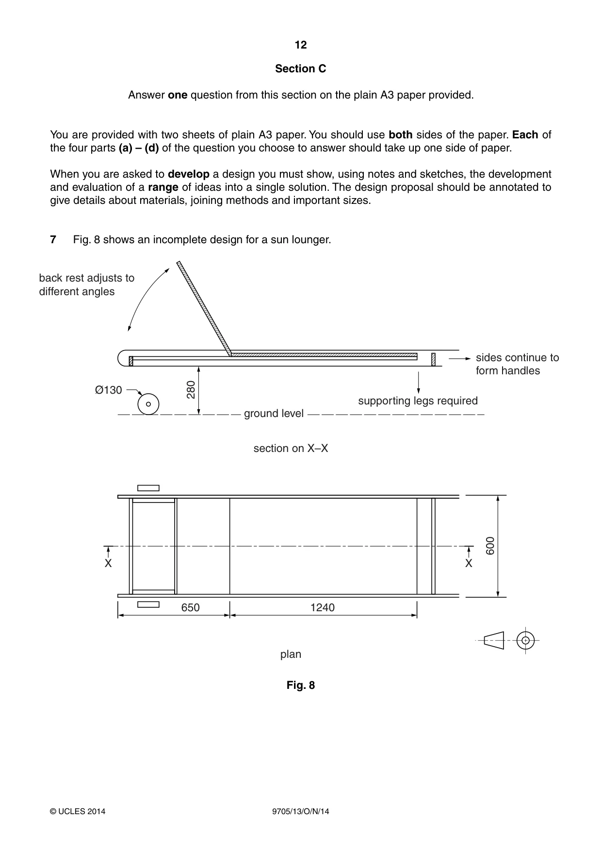
12 9705/13/O/N/14 © UCLES 2014 Section C Answer one question from this section on the plain A3 paper provided. You are provided with two sheets of plain A3 paper. You should use both sides of the paper. Each of the four parts (a) – (d) of the question you choose to answer should take up one side of paper. When you are asked to develop a design you must show, using notes and sketches, the development and evaluation of a range of ideas into a single solution. The design proposal should be annotated to give details about materials, joining methods and important sizes. 7 Fig. 8 shows an incomplete design for a sun lounger. 280 Ø130 ground level section on X–X supporting legs required sides continue to form handles back rest adjusts to different angles X X 600 650 1240 plan Fig. 8
Question paper, page 13
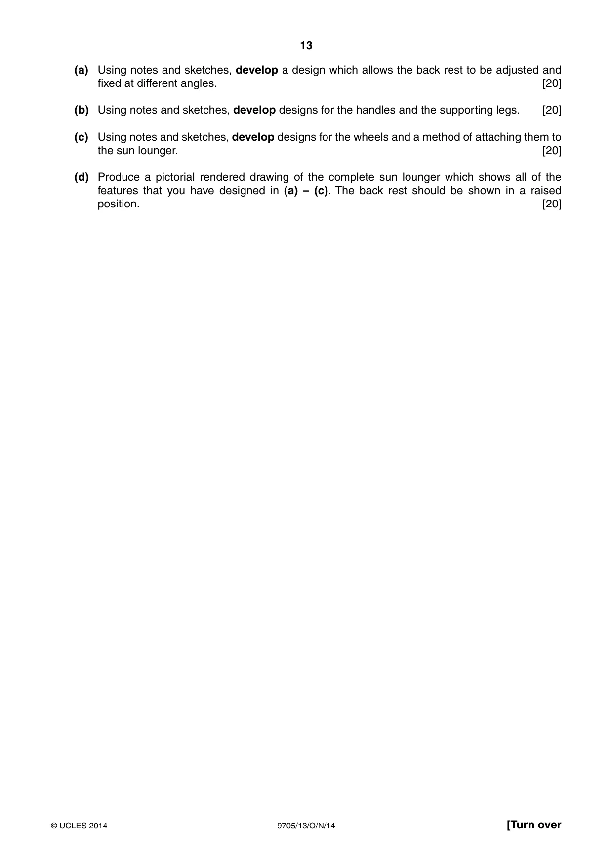
13 9705/13/O/N/14 © UCLES 2014 [Turn over (a) Using notes and sketches, develop a design which allows the back rest to be adjusted and fixed at different angles. [20] (b) Using notes and sketches, develop designs for the handles and the supporting legs. [20] (c) Using notes and sketches, develop designs for the wheels and a method of attaching them to the sun lounger. [20] (d) Produce a pictorial rendered drawing of the complete sun lounger which shows all of the features that you have designed in (a) – (c). The back rest should be shown in a raised position. [20]
Question paper, page 14
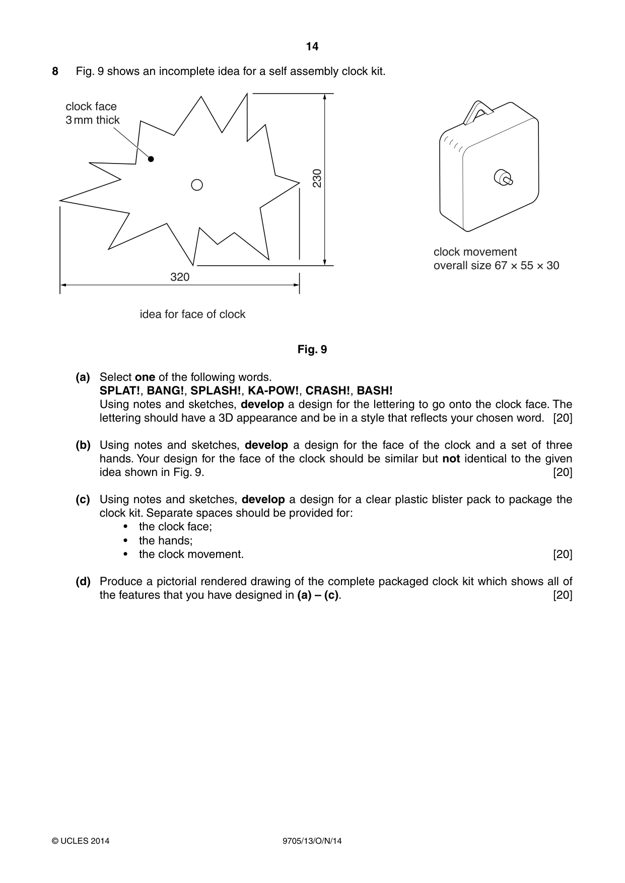
14 9705/13/O/N/14 © UCLES 2014 8 Fig. 9 shows an incomplete idea for a self assembly clock kit. 230 320 idea for face of clock clock face 3 mm thick clock movement overall size 67 × 55 × 30 Fig. 9 (a) Select one of the following words. SPLAT!, BANG!, SPLASH!, KA-POW!, CRASH!, BASH! Using notes and sketches, develop a design for the lettering to go onto the clock face. The lettering should have a 3D appearance and be in a style that reflects your chosen word. [20] (b) Using notes and sketches, develop a design for the face of the clock and a set of three hands. Your design for the face of the clock should be similar but not identical to the given idea shown in Fig. 9. [20] (c) Using notes and sketches, develop a design for a clear plastic blister pack to package the clock kit. Separate spaces should be provided for: • the clock face; • the hands; • the clock movement. [20] (d) Produce a pictorial rendered drawing of the complete packaged clock kit which shows all of the features that you have designed in (a) – (c). [20]
Question paper, page 15
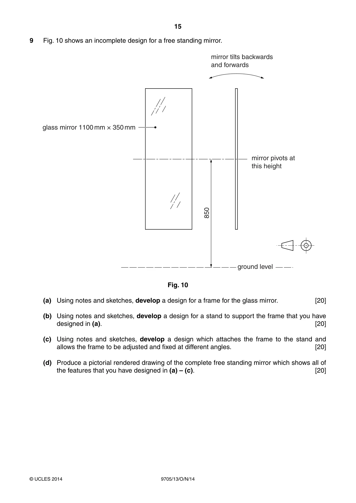
15 9705/13/O/N/14 © UCLES 2014 9 Fig. 10 shows an incomplete design for a free standing mirror. 850 glass mirror 1100 mm × 350 mm mirror tilts backwards and forwards mirror pivots at this height ground level Fig. 10 (a) Using notes and sketches, develop a design for a frame for the glass mirror. [20] (b) Using notes and sketches, develop a design for a stand to support the frame that you have designed in (a). [20] (c) Using notes and sketches, develop a design which attaches the frame to the stand and allows the frame to be adjusted and fixed at different angles. [20] (d) Produce a pictorial rendered drawing of the complete free standing mirror which shows all of the features that you have designed in (a) – (c). [20]
Question paper, page 16
16 9705/13/O/N/14 © UCLES 2014 Permission to reproduce items where third-party owned material protected by copyright is included has been sought and cleared where possible. Every reasonable effort has been made by the publisher (UCLES) to trace copyright holders, but if any items requiring clearance have unwittingly been included, the publisher will be pleased to make amends at the earliest possible opportunity. Cambridge International Examinations is part of the Cambridge Assessment Group. Cambridge Assessment is the brand name of University of Cambridge Local Examinations Syndicate (UCLES), which is itself a department of the University of Cambridge. BLANK PAGE
Mark scheme, page 1
® IGCSE is the registered trademark of Cambridge International Examinations. CAMBRIDGE INTERNATIONAL EXAMINATIONS Cambridge International Advanced Subsidiary and Advanced Level MARK SCHEME for the October/November 2014 series 9705 DESIGN AND TECHNOLOGY 9705/13 Paper 1, maximum raw mark 120 This mark scheme is published as an aid to teachers and candidates, to indicate the requirements of the examination. It shows the basis on which Examiners were instructed to award marks. It does not indicate the details of the discussions that took place at an Examiners’ meeting before marking began, which would have considered the acceptability of alternative answers. Mark schemes should be read in conjunction with the question paper and the Principal Examiner Report for Teachers. Cambridge will not enter into discussions about these mark schemes. Cambridge is publishing the mark schemes for the October/November 2014 series for most Cambridge IGCSE®, Cambridge International A and AS Level components and some Cambridge O Level components.
Mark scheme, page 2
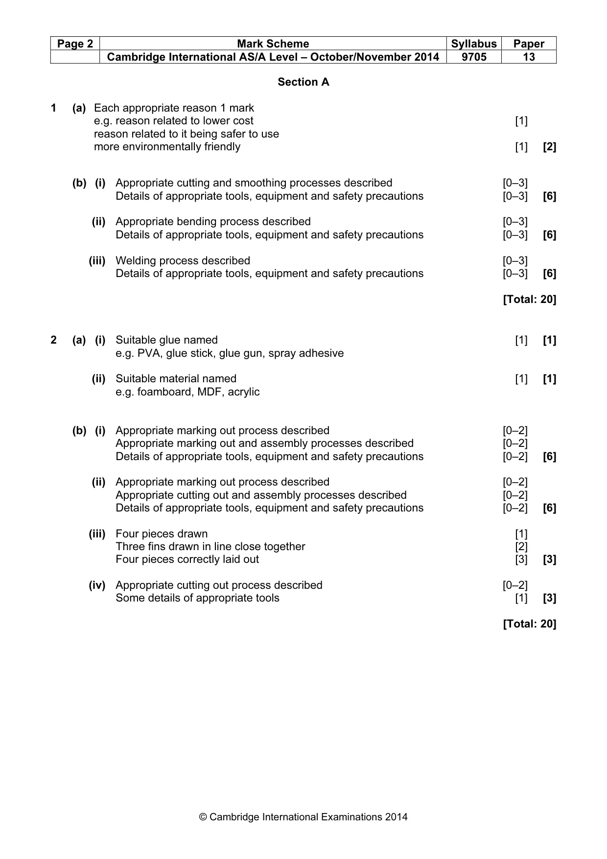
Page 2 Mark Scheme Syllabus Paper Cambridge International AS/A Level – October/November 2014 9705 13 © Cambridge International Examinations 2014 Section A 1 (a) Each appropriate reason 1 mark e.g. reason related to lower cost [1] reason related to it being safer to use more environmentally friendly [1] [2] (b) (i) Appropriate cutting and smoothing processes described [0–3] Details of appropriate tools, equipment and safety precautions [0–3] [6] (ii) Appropriate bending process described [0–3] Details of appropriate tools, equipment and safety precautions [0–3] [6] (iii) Welding process described [0–3] Details of appropriate tools, equipment and safety precautions [0–3] [6] [Total: 20] 2 (a) (i) Suitable glue named [1] [1] e.g. PVA, glue stick, glue gun, spray adhesive (ii) Suitable material named [1] [1] e.g. foamboard, MDF, acrylic (b) (i) Appropriate marking out process described [0–2] Appropriate marking out and assembly processes described [0–2] Details of appropriate tools, equipment and safety precautions [0–2] [6] (ii) Appropriate marking out process described [0–2] Appropriate cutting out and assembly processes described [0–2] Details of appropriate tools, equipment and safety precautions [0–2] [6] (iii) Four pieces drawn [1] Three fins drawn in line close together [2] Four pieces correctly laid out [3] [3] (iv) Appropriate cutting out process described [0–2] Some details of appropriate tools [1] [3] [Total: 20]
Mark scheme, page 3
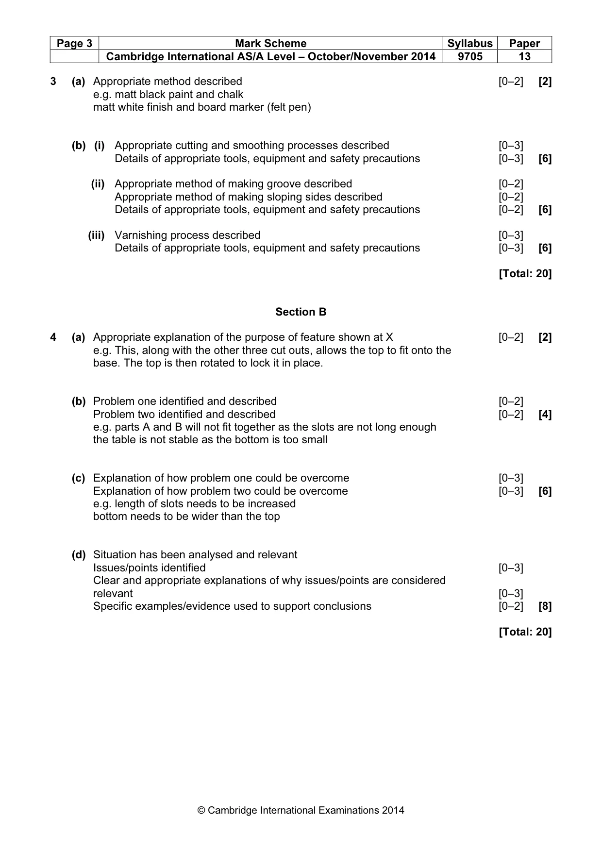
Page 3 Mark Scheme Syllabus Paper Cambridge International AS/A Level – October/November 2014 9705 13 © Cambridge International Examinations 2014 3 (a) Appropriate method described [0–2] [2] e.g. matt black paint and chalk matt white finish and board marker (felt pen) (b) (i) Appropriate cutting and smoothing processes described [0–3] Details of appropriate tools, equipment and safety precautions [0–3] [6] (ii) Appropriate method of making groove described [0–2] Appropriate method of making sloping sides described [0–2] Details of appropriate tools, equipment and safety precautions [0–2] [6] (iii) Varnishing process described [0–3] Details of appropriate tools, equipment and safety precautions [0–3] [6] [Total: 20] Section B 4 (a) Appropriate explanation of the purpose of feature shown at X [0–2] [2] e.g. This, along with the other three cut outs, allows the top to fit onto the base. The top is then rotated to lock it in place. (b) Problem one identified and described [0–2] Problem two identified and described [0–2] [4] e.g. parts A and B will not fit together as the slots are not long enough the table is not stable as the bottom is too small (c) Explanation of how problem one could be overcome [0–3] Explanation of how problem two could be overcome [0–3] [6] e.g. length of slots needs to be increased bottom needs to be wider than the top (d) Situation has been analysed and relevant Issues/points identified [0–3] Clear and appropriate explanations of why issues/points are considered relevant [0–3] Specific examples/evidence used to support conclusions [0–2] [8] [Total: 20]
Mark scheme, page 4
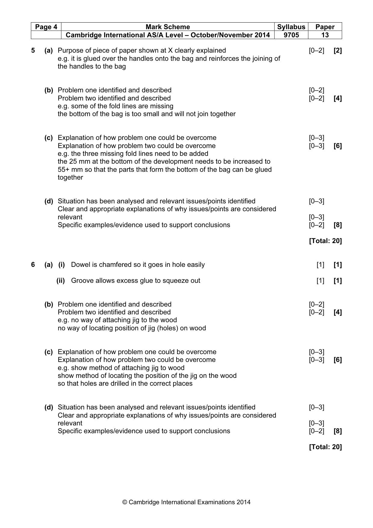
Page 4 Mark Scheme Syllabus Paper Cambridge International AS/A Level – October/November 2014 9705 13 © Cambridge International Examinations 2014 5 (a) Purpose of piece of paper shown at X clearly explained [0–2] [2] e.g. it is glued over the handles onto the bag and reinforces the joining of the handles to the bag (b) Problem one identified and described [0–2] Problem two identified and described [0–2] [4] e.g. some of the fold lines are missing the bottom of the bag is too small and will not join together (c) Explanation of how problem one could be overcome [0–3] Explanation of how problem two could be overcome [0–3] [6] e.g. the three missing fold lines need to be added the 25 mm at the bottom of the development needs to be increased to 55+ mm so that the parts that form the bottom of the bag can be glued together (d) Situation has been analysed and relevant issues/points identified [0–3] Clear and appropriate explanations of why issues/points are considered relevant [0–3] Specific examples/evidence used to support conclusions [0–2] [8] [Total: 20] 6 (a) (i) Dowel is chamfered so it goes in hole easily [1] [1] (ii) Groove allows excess glue to squeeze out [1] [1] (b) Problem one identified and described [0–2] Problem two identified and described [0–2] [4] e.g. no way of attaching jig to the wood no way of locating position of jig (holes) on wood (c) Explanation of how problem one could be overcome [0–3] Explanation of how problem two could be overcome [0–3] [6] e.g. show method of attaching jig to wood show method of locating the position of the jig on the wood so that holes are drilled in the correct places (d) Situation has been analysed and relevant issues/points identified [0–3] Clear and appropriate explanations of why issues/points are considered relevant [0–3] Specific examples/evidence used to support conclusions [0–2] [8] [Total: 20]
Mark scheme, page 5
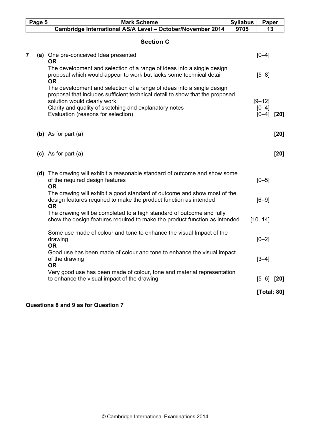
Page 5 Mark Scheme Syllabus Paper Cambridge International AS/A Level – October/November 2014 9705 13 © Cambridge International Examinations 2014 Section C 7 (a) One pre-conceived Idea presented [0–4] OR The development and selection of a range of ideas into a single design proposal which would appear to work but lacks some technical detail [5–8] OR The development and selection of a range of ideas into a single design proposal that includes sufficient technical detail to show that the proposed solution would clearly work [9–12] Clarity and quality of sketching and explanatory notes [0–4] Evaluation (reasons for selection) [0–4] [20] (b) As for part (a) [20] (c) As for part (a) [20] (d) The drawing will exhibit a reasonable standard of outcome and show some of the required design features [0–5] OR The drawing will exhibit a good standard of outcome and show most of the design features required to make the product function as intended [6–9] OR The drawing will be completed to a high standard of outcome and fully show the design features required to make the product function as intended [10–14] Some use made of colour and tone to enhance the visual Impact of the drawing [0–2] OR Good use has been made of colour and tone to enhance the visual impact of the drawing [3–4] OR Very good use has been made of colour, tone and material representation to enhance the visual impact of the drawing [5–6] [20] [Total: 80] Questions 8 and 9 as for Question 7
What you needed in this session
Cambridge’s own grade thresholds for 2014 Oct/Nov, Paper 1 · Variant 3. A higher threshold means an easier paper — the bar moves with how the cohort did.