Cambridge IGCSE Physics 0625 — 2023 Oct/Nov Paper 5 · Variant 3
0625/53/O/N/23 · 4 questions · 40 marks · ≈45 min
The question paper and its mark scheme, free to read here and free to download. This is Cambridge’s own paper, exactly as it was sat.
Question paper12 pages


Mark scheme8 pages
Answers below. Sit the paper first if you are practising.
Questions as text
Q1 · In this experiment, you will determine the density of sand by two methods
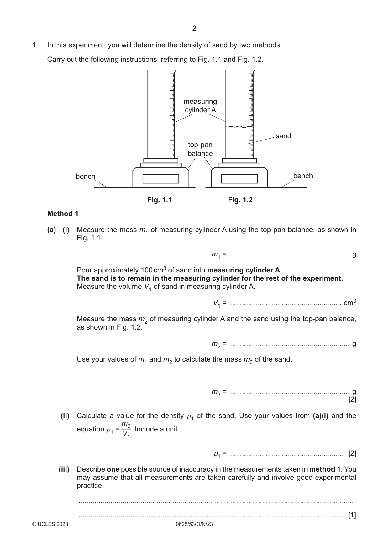
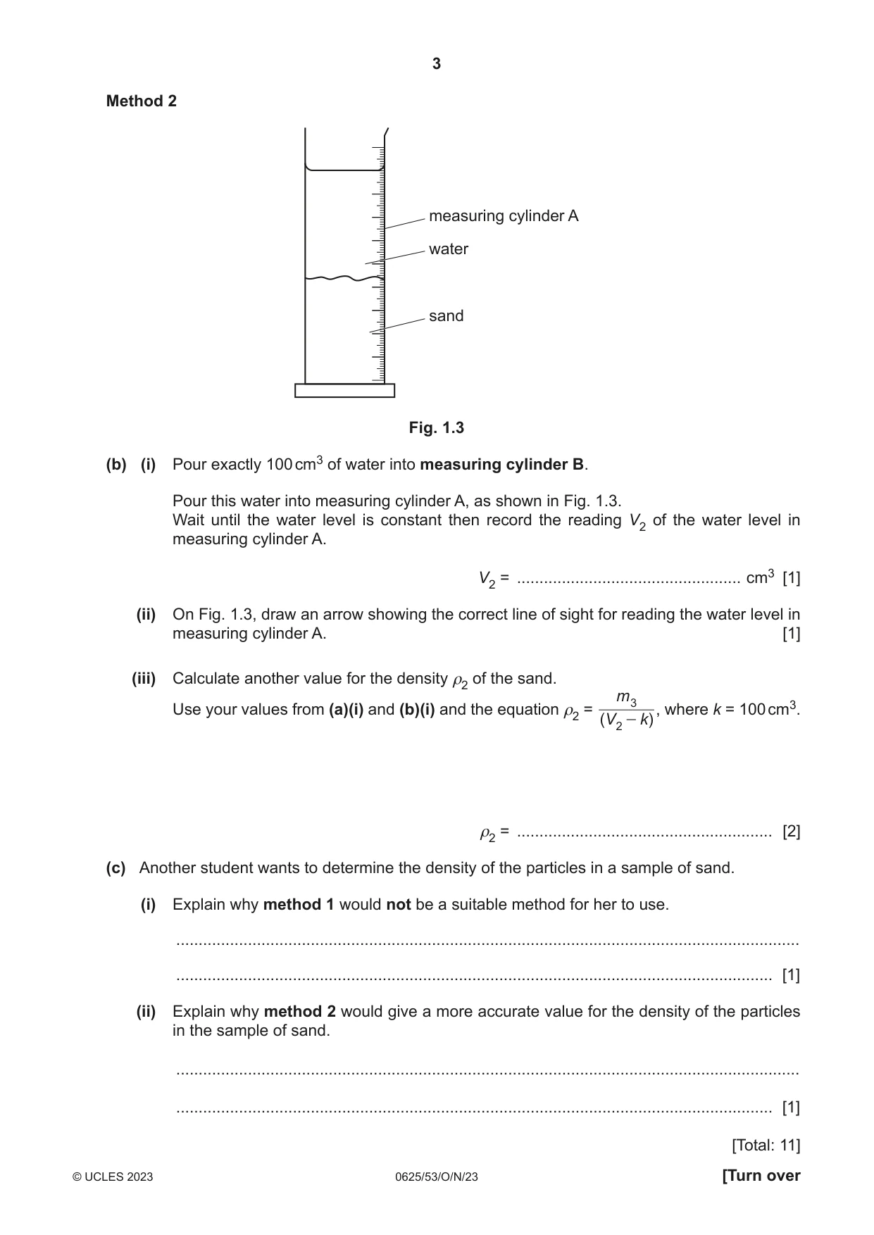
1 In this experiment, you will determine the density of sand by two methods. Carry out the following instructions, referring to Fig. 1.1 and Fig. 1.2. measuring cylinder A sand top-pan balance bench bench Fig. 1.1 Fig. 1.2 Method 1 (a) (i) Measure the mass m1 of measuring cylinder A using the top-pan balance, as shown in Fig. 1.1. m1 = ............................................................ g Pour approximately 100 cm3 of sand into measuring cylinder A. The sand is to remain in the measuring cylinder for the rest of the experiment. Measure the volume V1 of sand in measuring cylinder A. V1 = ........................................................ cm3 Measure the mass m2 of measuring cylinder A and the sand using the top-pan balance, as shown in Fig. 1.2. m2 = ............................................................ g Use your values of m1 and m2 to calculate the mass m3 of the sand. m3 = ............................................................ g [2] (ii) Calculate a value for the density ρ1 of the sand. Use your values from (a)(i) and the m3 equation ρ1 = . Include a unit. V1 ρ1 = ......................................................... [2] (iii) Describe one possible source of inaccuracy in the measurements taken in method 1. You may assume that all measurements are taken carefully and involve good experimental practice. ........................................................................................................................................... ..................................................................................................................................... [1] Method 2 measuring cylinder A water sand Fig. 1.3 (b) (i) Pour exactly 100 cm3 of water into measuring cylinder B. Pour this water into measuring cylinder A, as shown in Fig. 1.3. Wait until the water level is constant then record the reading V2 of the water level in measuring cylinder A. V2 = .................................................. cm3 [1] (ii) On Fig. 1.3, draw an arrow showing the correct line of sight for reading the water level in measuring cylinder A. [1] (iii) Calculate another value for the density ρ2 of the sand. m 3 , where k = 100 cm3. Use your values from (a)(i) and (b)(i) and the equation ρ2 = (V 2 - k) ρ2 = ......................................................... [2] (c) Another student wants to determine the density of the particles in a sample of sand. (i) Explain why method 1 would not be a suitable method for her to use. ........................................................................................................................................... ..................................................................................................................................... [1] (ii) Explain why method 2 would give a more accurate value for the density of the particles in the sample of sand. ........................................................................................................................................... ..................................................................................................................................... [1] [Total: 11]
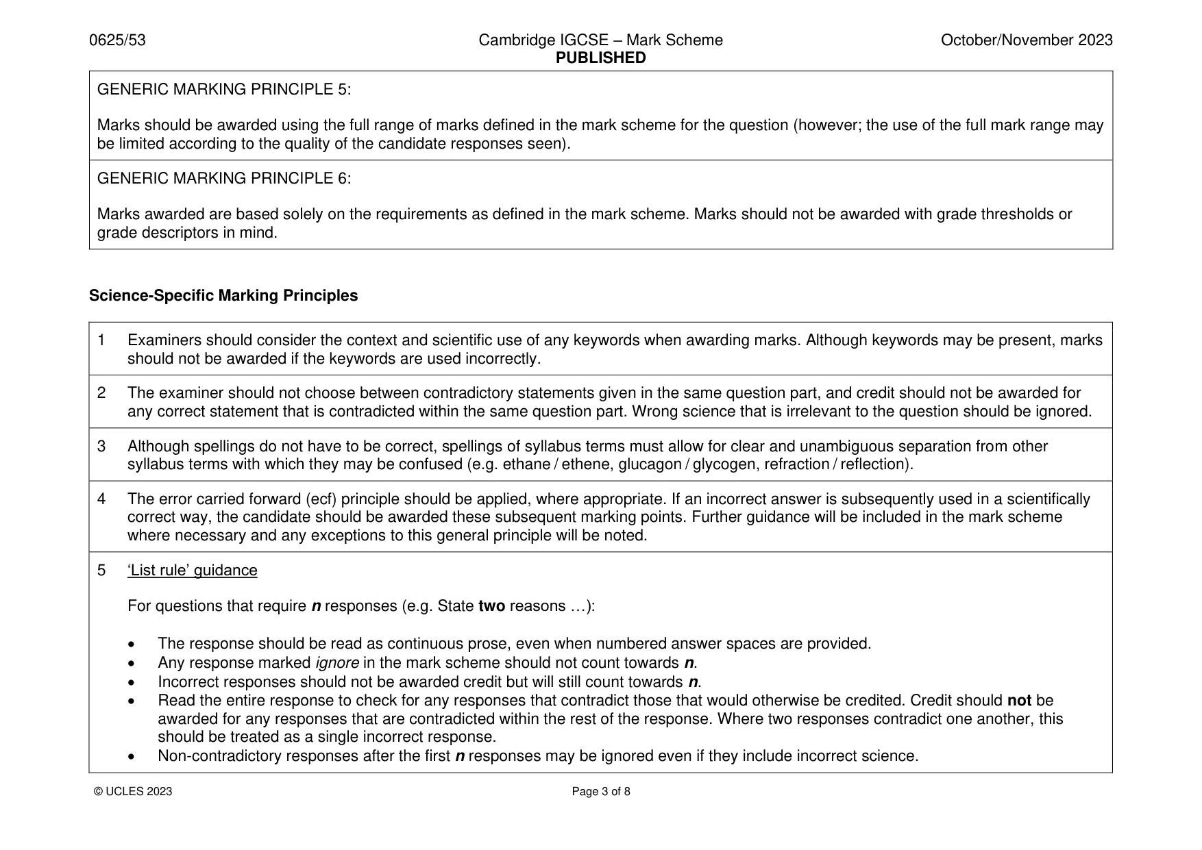
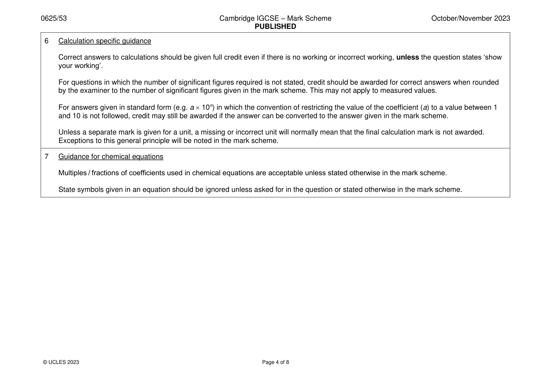
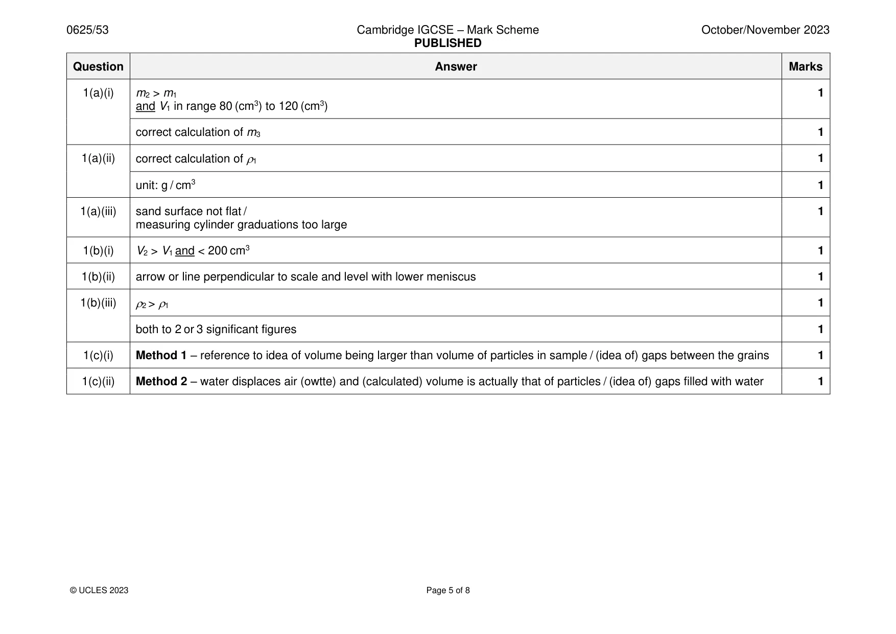
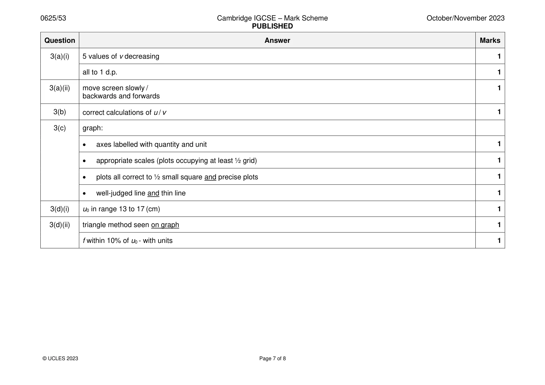
Mark scheme: Question Answer Marks 1(a)(i) m2 > m1 1 and V1 in range 80 (cm3) to 120 (cm3) correct calculation of m3 1 1(a)(ii) correct calculation of 1 1 unit: g / cm3 1 1(a)(iii) sand surface not flat / 1 measuring cylinder graduations too large 1(b)(i) V2 > V1 and < 200 cm3 1 1(b)(ii) arrow or line perpendicular to scale and level with lower meniscus 1 1(b)(iii) 2 > 1 1 both to 2 or 3 significant figures 1 1(c)(i) Method 1 – reference to idea of volume being larger than volume of particles in sample / (idea of) gaps between the grains 1 1(c)(ii) Method 2 – water displaces air (owtte) and (calculated) volume is actually that of particles / (idea of) gaps filled with water 1
Q2 · In this experiment, you will investigate the cooling of hot water in surroundings with…
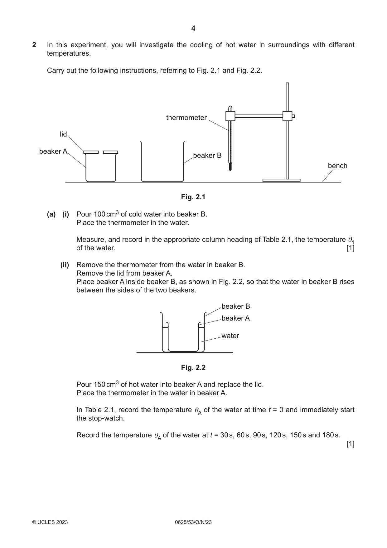
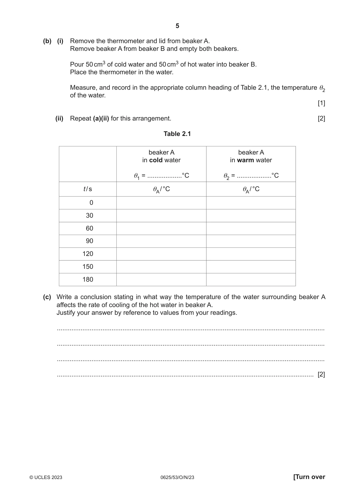
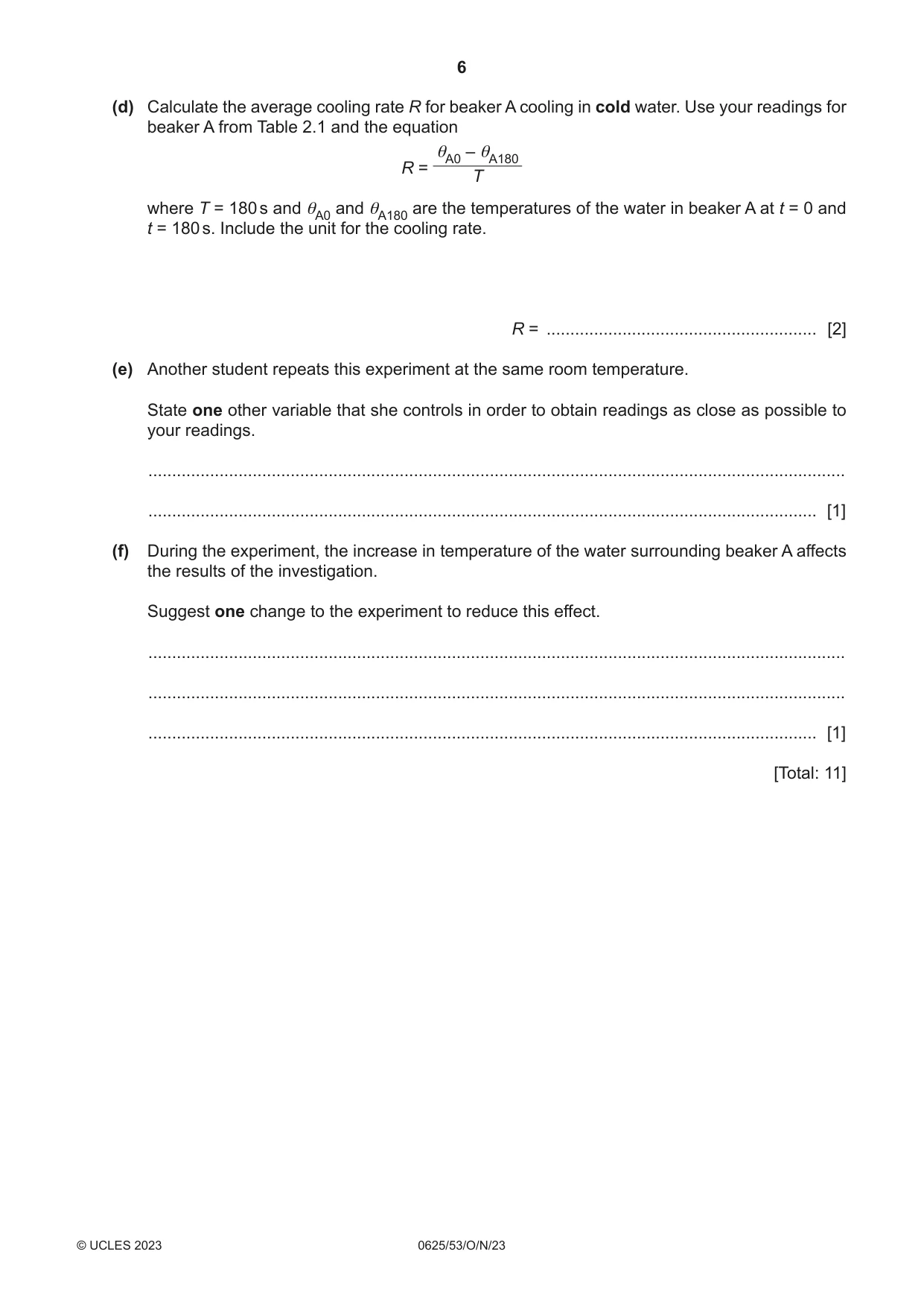
2 In this experiment, you will investigate the cooling of hot water in surroundings with different temperatures. Carry out the following instructions, referring to Fig. 2.1 and Fig. 2.2. thermometer lid beaker A beaker B bench Fig. 2.1 (a) (i) Pour 100 cm3 of cold water into beaker B. Place the thermometer in the water. Measure, and record in the appropriate column heading of Table 2.1, the temperature θ1 of the water. [1] (ii) Remove the thermometer from the water in beaker B. Remove the lid from beaker A. Place beaker A inside beaker B, as shown in Fig. 2.2, so that the water in beaker B rises between the sides of the two beakers. beaker B beaker A water Fig. 2.2 Pour 150 cm3 of hot water into beaker A and replace the lid. Place the thermometer in the water in beaker A. In Table 2.1, record the temperature θA of the water at time t = 0 and immediately start the stop-watch. Record the temperature θA of the water at t = 30 s, 60 s, 90 s, 120 s, 150 s and 180 s. [1] (b) (i) Remove the thermometer and lid from beaker A. Remove beaker A from beaker B and empty both beakers. Pour 50 cm3 of cold water and 50 cm3 of hot water into beaker B. Place the thermometer in the water. Measure, and record in the appropriate column heading of Table 2.1, the temperature θ2 of the water. [1] (ii) Repeat (a)(ii) for this arrangement. [2] Table 2.1 beaker A beaker A in cold water in warm water θ1 = ...................°C θ2 = ...................°C t / s θA / °C θA / °C 0 30 60 90 120 150 180 (c) Write a conclusion stating in what way the temperature of the water surrounding beaker A affects the rate of cooling of the hot water in beaker A. Justify your answer by reference to values from your readings. ................................................................................................................................................... ................................................................................................................................................... ................................................................................................................................................... ............................................................................................................................................. [2] (d) Calculate the average cooling rate R for beaker A cooling in cold water. Use your readings for beaker A from Table 2.1 and the equation θA0 – θA180 R = T where T = 180 s and θA0 and θA180 are the temperatures of the water in beaker A at t = 0 and t = 180 s. Include the unit for the cooling rate. R = ......................................................... [2] (e) Another student repeats this experiment at the same room temperature. State one other variable that she controls in order to obtain readings as close as possible to your readings. ................................................................................................................................................... ............................................................................................................................................. [1] (f) During the experiment, the increase in temperature of the water surrounding beaker A affects the results of the investigation. Suggest one change to the experiment to reduce this effect. ................................................................................................................................................... ................................................................................................................................................... ............................................................................................................................................. [1] [Total: 11]
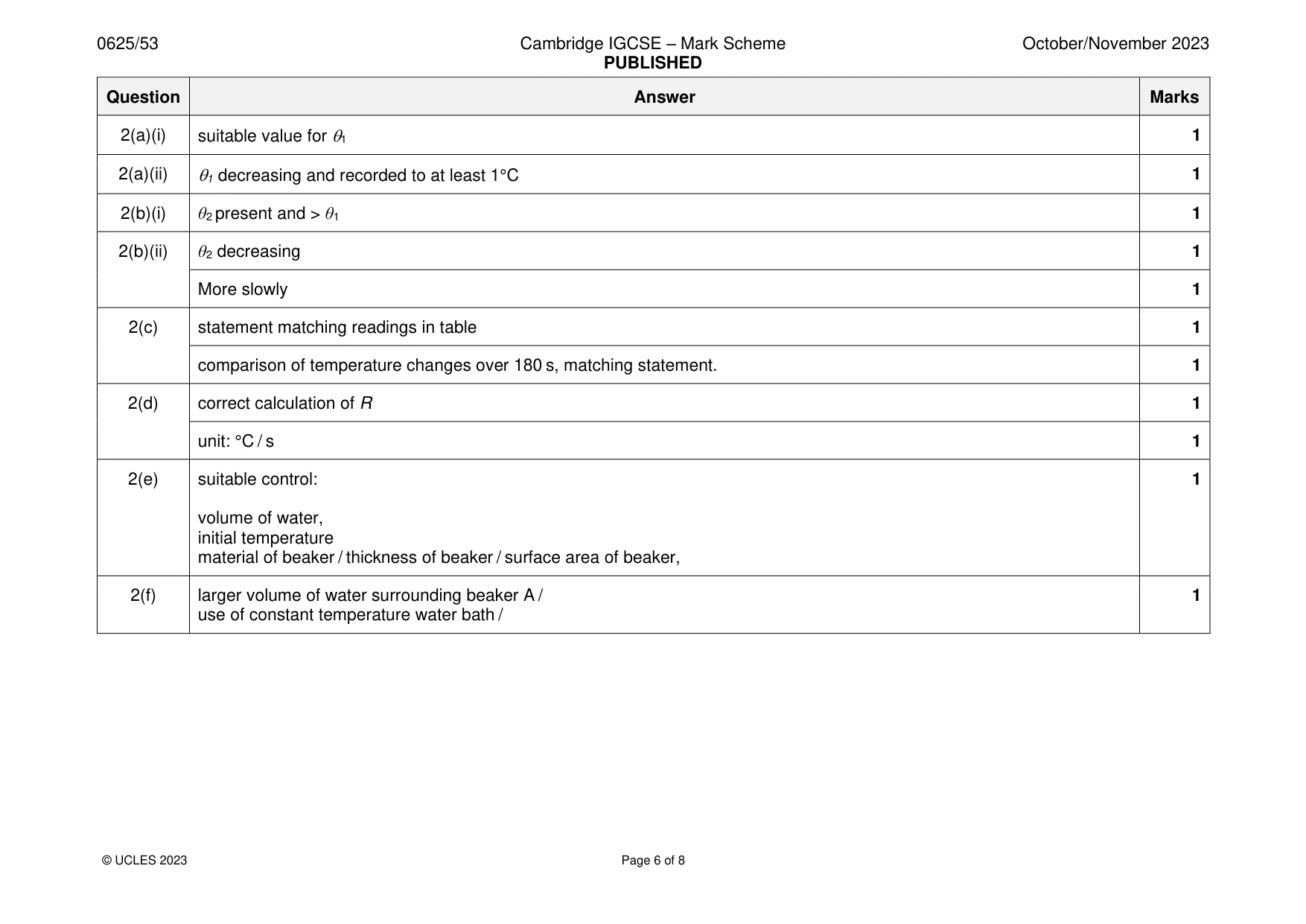
Mark scheme: 2(a)(i) suitable value for 1 1 2(a)(ii) 1 decreasing and recorded to at least 1°C 1 2(b)(i) θ2 present and > θ1 1 2(b)(ii) θ2 decreasing 1 More slowly 1 2(c) statement matching readings in table 1 comparison of temperature changes over 180 s, matching statement. 1 2(d) correct calculation of R 1 unit: °C / s 1 2(e) suitable control: 1 volume of water, initial temperature material of beaker / thickness of beaker / surface area of beaker, 2(f) larger volume of water surrounding beaker A / 1 use of constant temperature water bath /
Q3 · In this experiment, you will determine the focal length of a converging lens
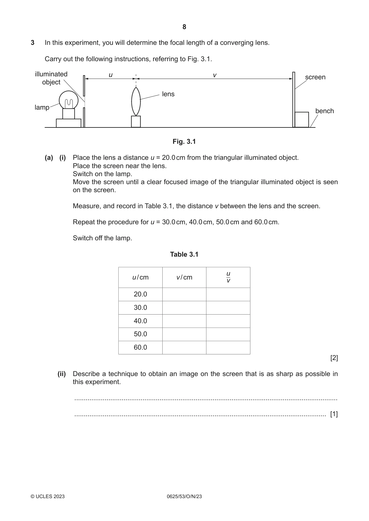
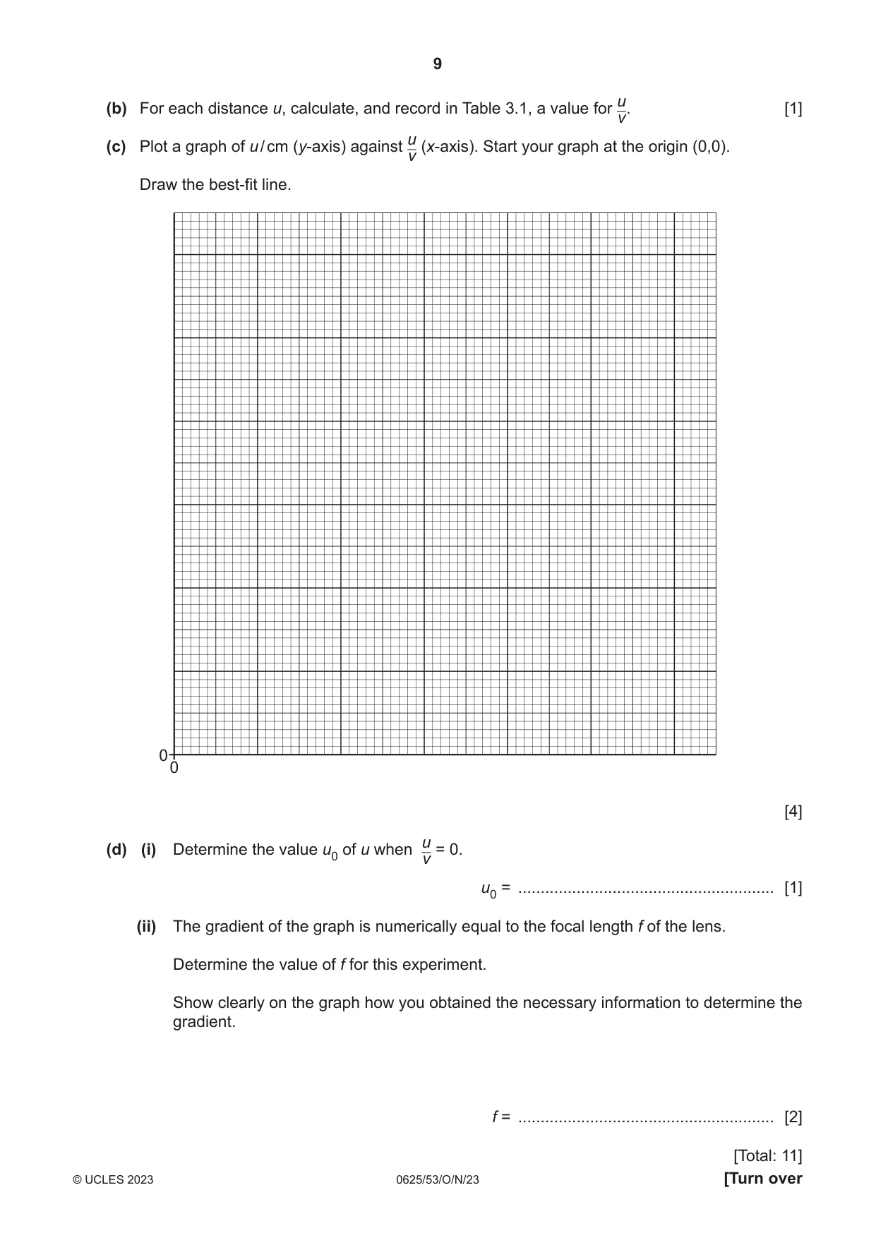
3 In this experiment, you will determine the focal length of a converging lens. Carry out the following instructions, referring to Fig. 3.1. illuminated u v screen object lens lamp bench Fig. 3.1 (a) (i) Place the lens a distance u = 20.0 cm from the triangular illuminated object. Place the screen near the lens. Switch on the lamp. Move the screen until a clear focused image of the triangular illuminated object is seen on the screen. Measure, and record in Table 3.1, the distance v between the lens and the screen. Repeat the procedure for u = 30.0 cm, 40.0 cm, 50.0 cm and 60.0 cm. Switch off the lamp. Table 3.1 u u / cm v / cm v 20.0 30.0 40.0 50.0 60.0 [2] (ii) Describe a technique to obtain an image on the screen that is as sharp as possible in this experiment. ........................................................................................................................................... ..................................................................................................................................... [1] u (b) For each distance u, calculate, and record in Table 3.1, a value for v. [1] u(c) Plot a graph of u / cm (y-axis) against (x-axis). Start your graph at the origin (0,0). v Draw the best-fit line. 0 0 [4] u(d) (i) Determine the value u0 of u when = 0. v u0 = ......................................................... [1] (ii) The gradient of the graph is numerically equal to the focal length f of the lens. Determine the value of f for this experiment. Show clearly on the graph how you obtained the necessary information to determine the gradient. f = ......................................................... [2] [Total: 11]
Mark scheme: 3(a)(i) 5 values of v decreasing 1 all to 1 d.p. 1 3(a)(ii) move screen slowly / 1 backwards and forwards 3(b) correct calculations of u / v 1 3(c) graph: • axes labelled with quantity and unit 1 • appropriate scales (plots occupying at least ½ grid) 1 • plots all correct to ½ small square and precise plots 1 • well-judged line and thin line 1 3(d)(i) u0 in range 13 to 17 (cm) 1 3(d)(ii) triangle method seen on graph 1 f within 10% of u0 - with units 1
Q4 · A student investigates the brightness of a lamp
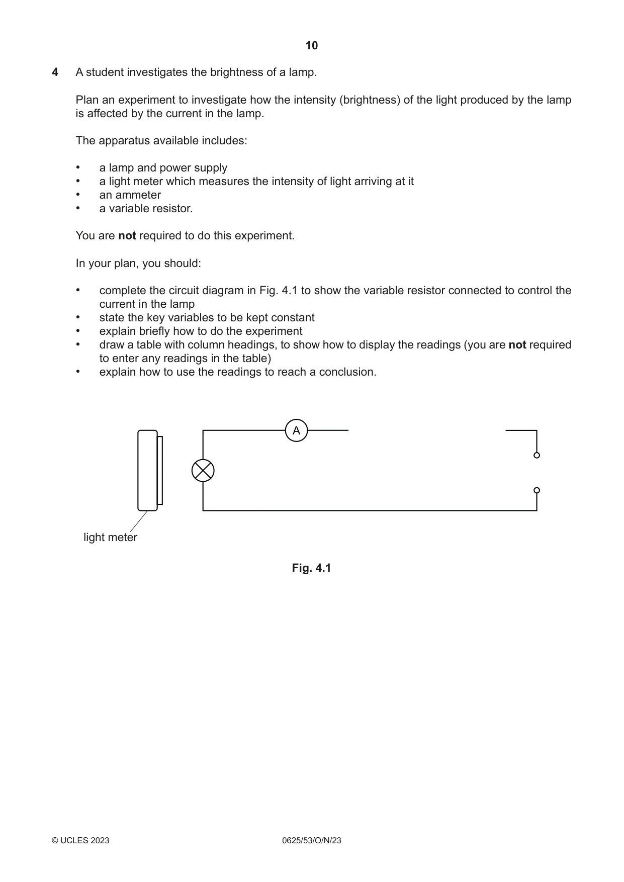
4 A student investigates the brightness of a lamp. Plan an experiment to investigate how the intensity (brightness) of the light produced by the lamp is affected by the current in the lamp. The apparatus available includes: • a lamp and power supply • a light meter which measures the intensity of light arriving at it • an ammeter • a variable resistor. You are not required to do this experiment. In your plan, you should: • complete the circuit diagram in Fig. 4.1 to show the variable resistor connected to control the current in the lamp • state the key variables to be kept constant • explain briefly how to do the experiment • draw a table with column headings, to show how to display the readings (you are not required to enter any readings in the table) • explain how to use the readings to reach a conclusion. A light meter Fig. 4.1 .......................................................................................................................................................... .......................................................................................................................................................... .......................................................................................................................................................... .......................................................................................................................................................... .......................................................................................................................................................... .......................................................................................................................................................... .......................................................................................................................................................... .......................................................................................................................................................... .......................................................................................................................................................... .......................................................................................................................................................... .......................................................................................................................................................... .......................................................................................................................................................... .......................................................................................................................................................... .......................................................................................................................................................... .......................................................................................................................................................... .......................................................................................................................................................... .......................................................................................................................................................... .......................................................................................................................................................... .......................................................................................................................................................... .................................................................................................................................................... [7]
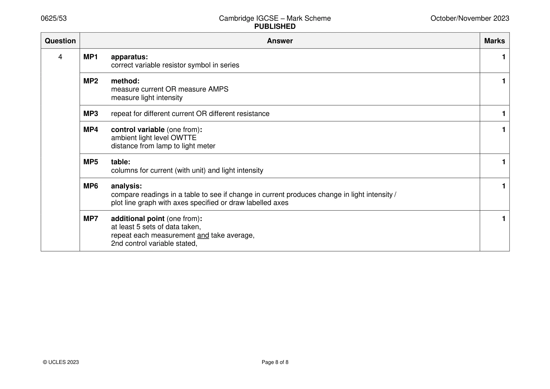
Mark scheme: 4 MP1 apparatus: 1 correct variable resistor symbol in series MP2 method: 1 measure current OR measure AMPS measure light intensity MP3 repeat for different current OR different resistance 1 MP4 control variable (one from): 1 ambient light level OWTTE distance from lamp to light meter MP5 table: 1 columns for current (with unit) and light intensity MP6 analysis: 1 compare readings in a table to see if change in current produces change in light intensity / plot line graph with axes specified or draw labelled axes MP7 additional point (one from): 1 at least 5 sets of data taken, repeat each measurement and take average, 2nd control variable stated,
What was in this paper
The subtopics covered by these 4 questions, and how many questions each got. Open one in a new tab to see every Cambridge question on it.
What you needed in this session
Cambridge’s own grade thresholds for 2023 Oct/Nov, Paper 5 · Variant 3. A higher threshold means an easier paper — the bar moves with how the cohort did.