Cambridge IGCSE Physics 0625 — 2022 Oct/Nov Paper 5 · Variant 1
0625/51/O/N/22 · 4 questions · 40 marks · ≈45 min
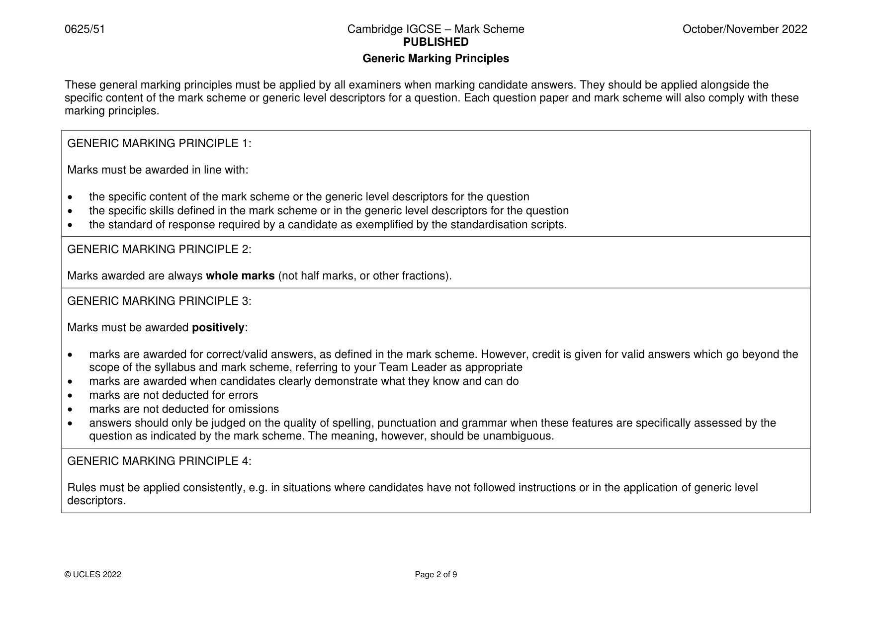
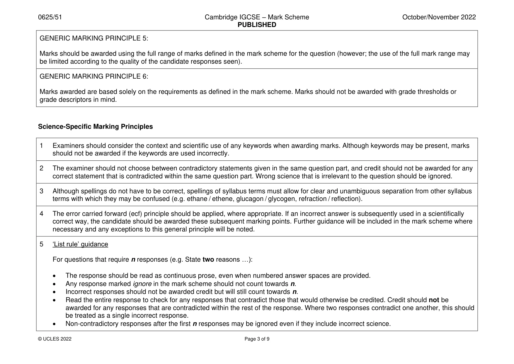
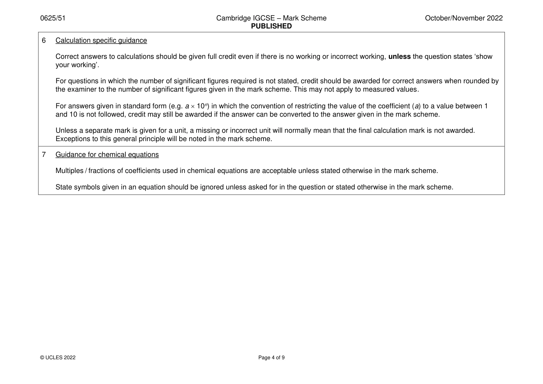
The question paper and its mark scheme, free to read here and free to download. This is Cambridge’s own paper, exactly as it was sat.
Question paper12 pages

Mark scheme9 pages
Answers below. Sit the paper first if you are practising.
Questions as text
Q1 · In this experiment, you will investigate the period of a pendulum
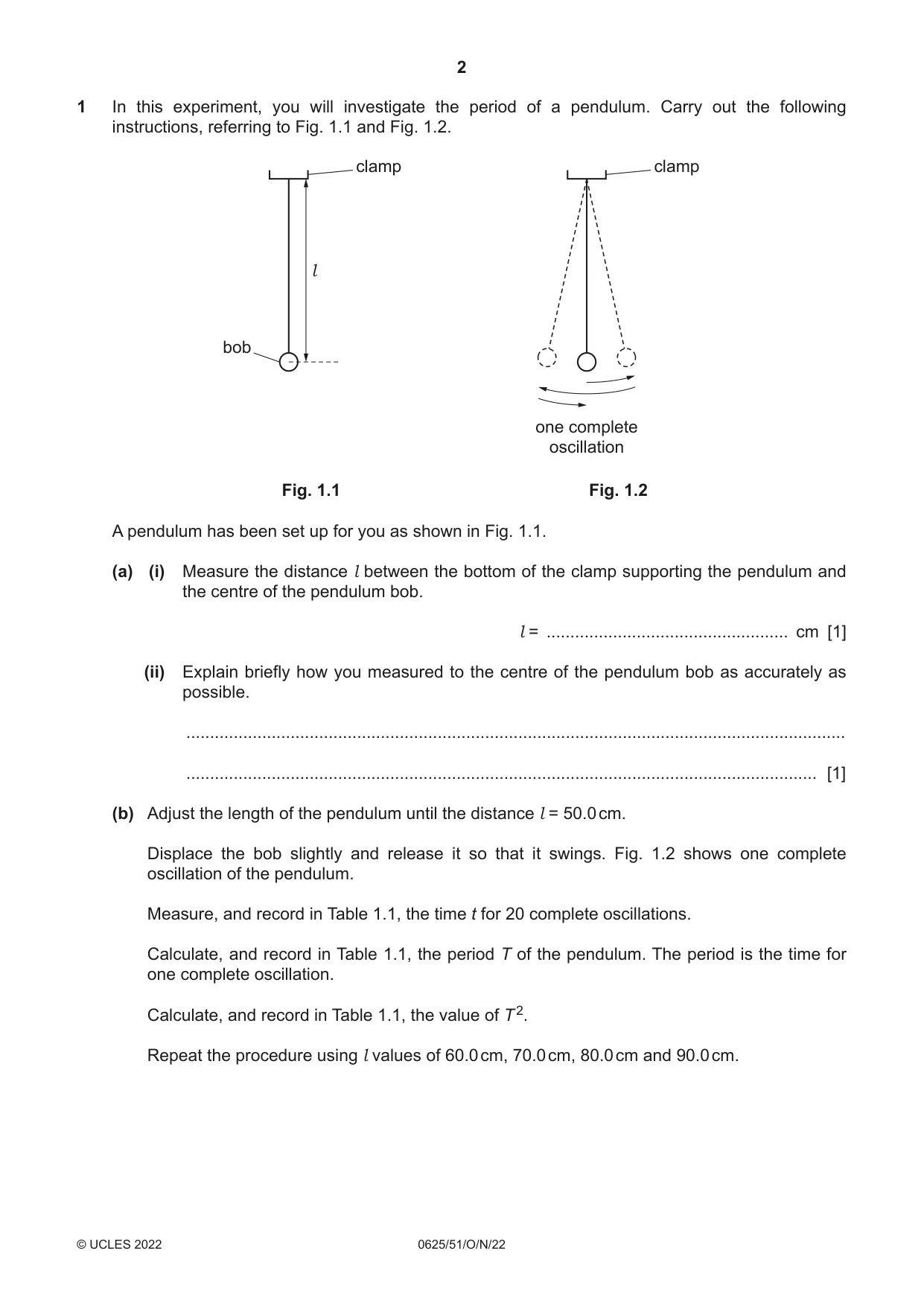
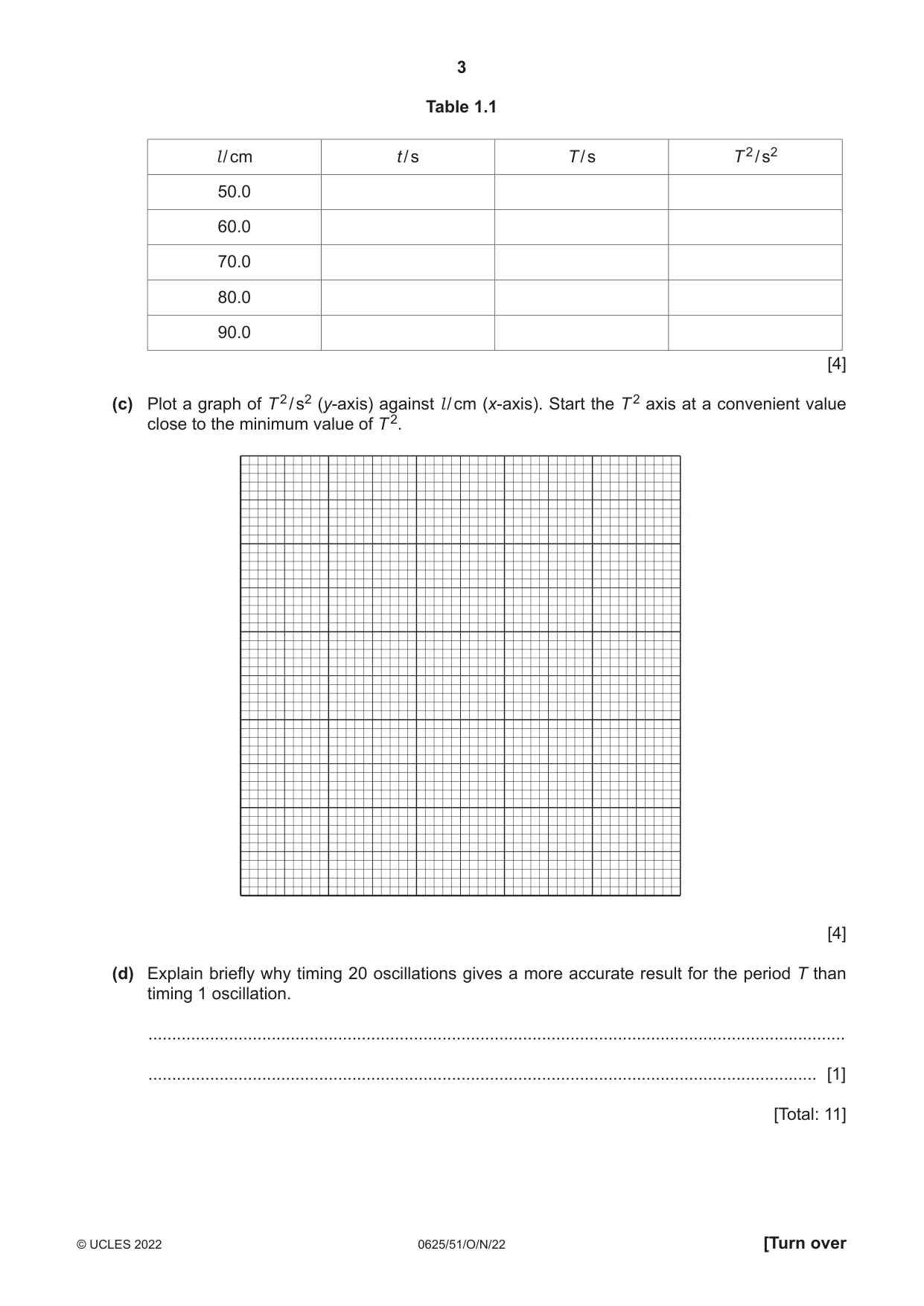
1 In this experiment, you will investigate the period of a pendulum. Carry out the following instructions, referring to Fig. 1.1 and Fig. 1.2. clamp clamp l bob one complete oscillation Fig. 1.1 Fig. 1.2 A pendulum has been set up for you as shown in Fig. 1.1. (a) (i) Measure the distance l between the bottom of the clamp supporting the pendulum and the centre of the pendulum bob. l = ................................................... cm [1] (ii) Explain briefly how you measured to the centre of the pendulum bob as accurately as possible. ........................................................................................................................................... ..................................................................................................................................... [1] (b) Adjust the length of the pendulum until the distance l = 50.0 cm. Displace the bob slightly and release it so that it swings. Fig. 1.2 shows one complete oscillation of the pendulum. Measure, and record in Table 1.1, the time t for 20 complete oscillations. Calculate, and record in Table 1.1, the period T of the pendulum. The period is the time for one complete oscillation. Calculate, and record in Table 1.1, the value of T 2. Repeat the procedure using l values of 60.0 cm, 70.0 cm, 80.0 cm and 90.0 cm. Table 1.1 l / cm t / s T / s T 2 / s2 50.0 60.0 70.0 80.0 90.0 [4] (c) Plot a graph of T 2 / s2 (y-axis) against l / cm (x-axis). Start the T 2 axis at a convenient value close to the minimum value of T 2. [4] (d) Explain briefly why timing 20 oscillations gives a more accurate result for the period T than timing 1 oscillation. ................................................................................................................................................... ............................................................................................................................................. [1] [Total: 11]
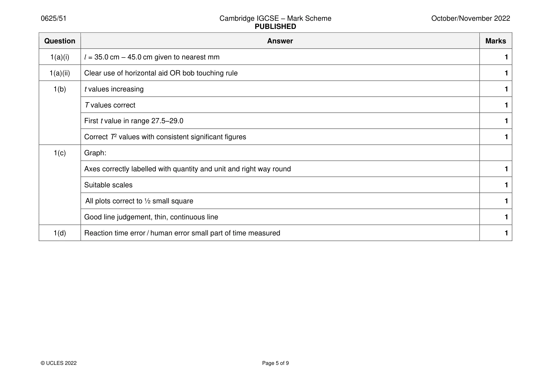
Mark scheme: Question Answer Marks 1(a)(i) l = 35.0 cm – 45.0 cm given to nearest mm 1 1(a)(ii) Clear use of horizontal aid OR bob touching rule 1 1(b) t values increasing 1 T values correct 1 First t value in range 27.5–29.0 1 Correct T2 values with consistent significant figures 1 1(c) Graph: Axes correctly labelled with quantity and unit and right way round 1 Suitable scales 1 All plots correct to ½ small square 1 Good line judgement, thin, continuous line 1 1(d) Reaction time error / human error small part of time measured 1
More questions on Physical quantities and measurement techniques
Q2 · In this experiment, you will investigate the resistance of a lamp
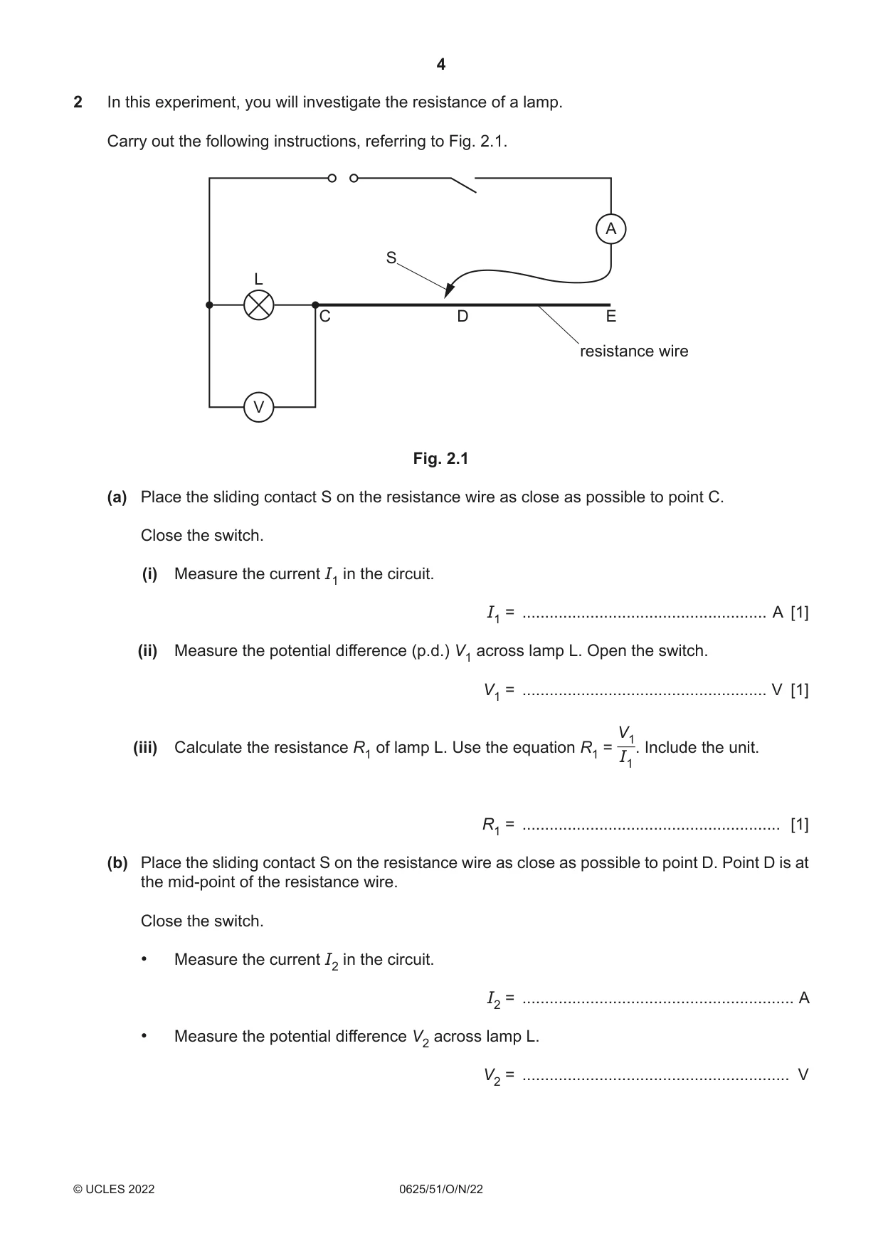
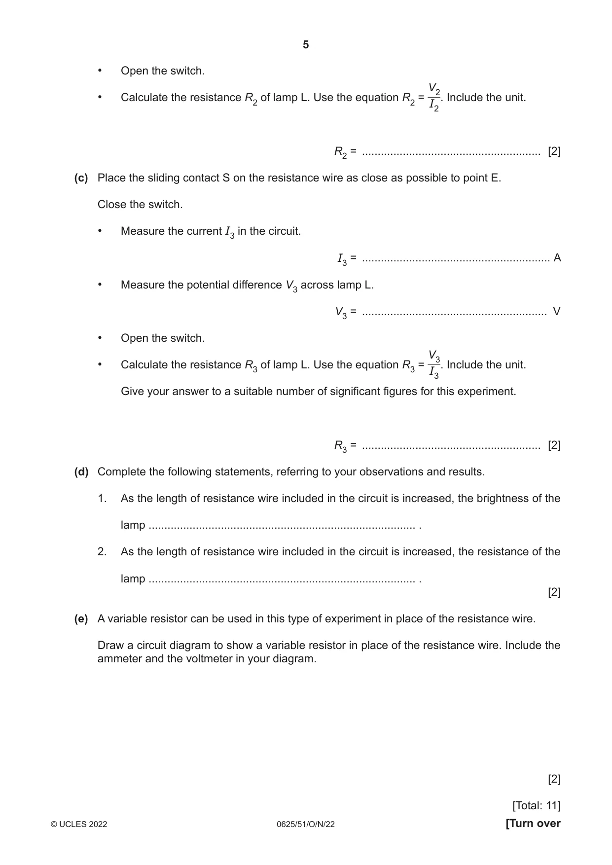
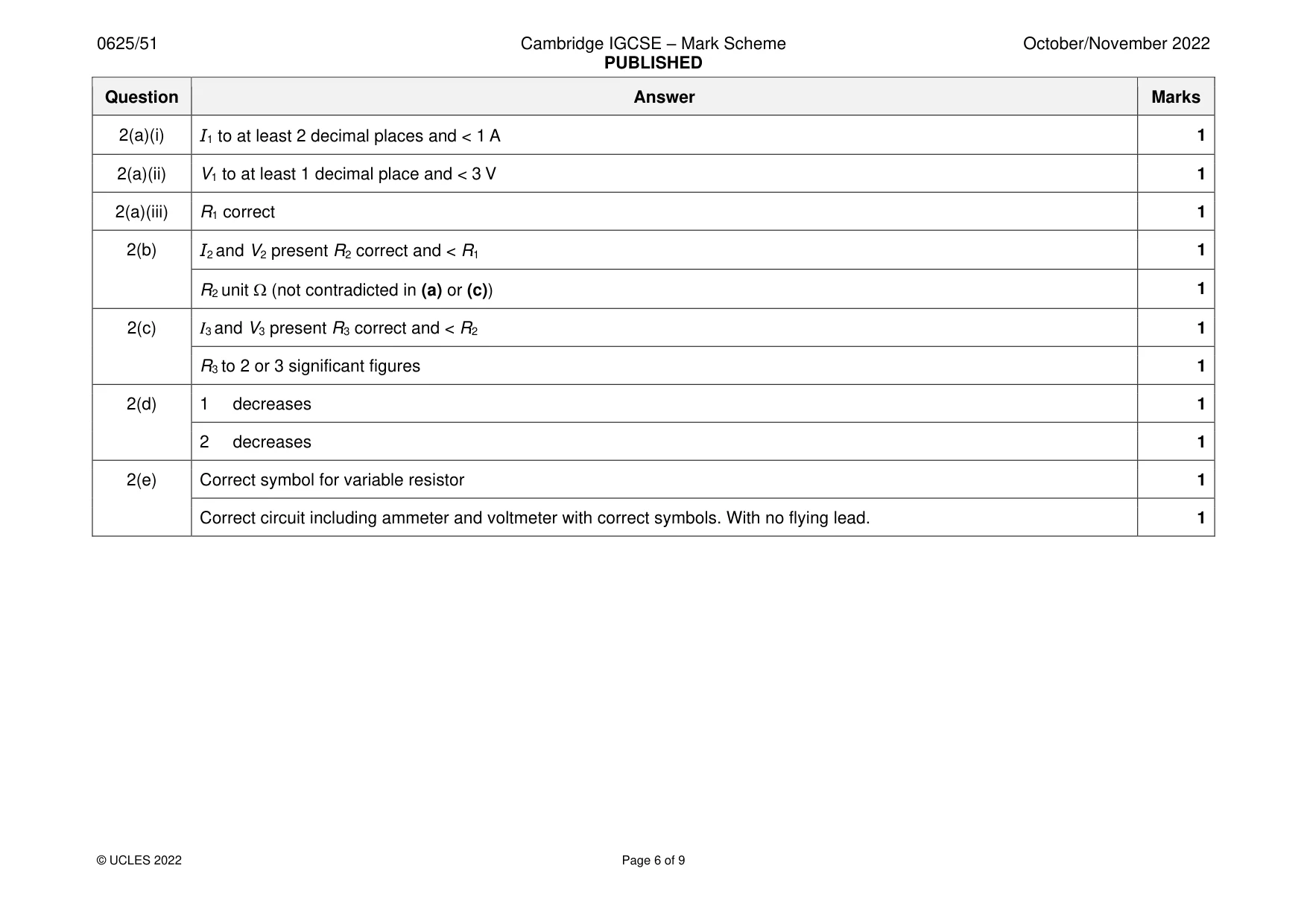
2 In this experiment, you will investigate the resistance of a lamp. Carry out the following instructions, referring to Fig. 2.1. A S L C D E resistance wire V Fig. 2.1 (a) Place the sliding contact S on the resistance wire as close as possible to point C. Close the switch. (i) Measure the current I1 in the circuit. I1 = ...................................................... A [1] (ii) Measure the potential difference (p.d.) V1 across lamp L. Open the switch. V1 = ...................................................... V [1] V1 (iii) Calculate the resistance R1 of lamp L. Use the equation R1 = . Include the unit. I1 R1 = ......................................................... [1] (b) Place the sliding contact S on the resistance wire as close as possible to point D. Point D is at the mid-point of the resistance wire. Close the switch. • Measure the current I2 in the circuit. I2 = ............................................................ A • Measure the potential difference V2 across lamp L. V2 = ........................................................... V • Open the switch. V2 • Calculate the resistance R2 of lamp L. Use the equation R2 = . Include the unit. I2 R2 = ......................................................... [2] (c) Place the sliding contact S on the resistance wire as close as possible to point E. Close the switch. • Measure the current I3 in the circuit. I3 = ............................................................ A • Measure the potential difference V3 across lamp L. V3 = ........................................................... V • Open the switch. V3 • Calculate the resistance R3 of lamp L. Use the equation R3 = . Include the unit. I3 Give your answer to a suitable number of significant figures for this experiment. R3 = ......................................................... [2] (d) Complete the following statements, referring to your observations and results. 1. As the length of resistance wire included in the circuit is increased, the brightness of the lamp ..................................................................................... . 2. As the length of resistance wire included in the circuit is increased, the resistance of the lamp ..................................................................................... . [2] (e) A variable resistor can be used in this type of experiment in place of the resistance wire. Draw a circuit diagram to show a variable resistor in place of the resistance wire. Include the ammeter and the voltmeter in your diagram. [2] [Total: 11]
Mark scheme: 2(a)(i) I1 to at least 2 decimal places and < 1 A 1 2(a)(ii) V1 to at least 1 decimal place and < 3 V 1 2(a)(iii) R1 correct 1 2(b) I2 and V2 present R2 correct and < R1 1 R2 unit (not contradicted in (a) or (c)) 1 2(c) I3 and V3 present R3 correct and < R2 1 R3 to 2 or 3 significant figures 1 2(d) 1 decreases 1 2 decreases 1 2(e) Correct symbol for variable resistor 1 Correct circuit including ammeter and voltmeter with correct symbols. With no flying lead. 1
Q3 · In this experiment, you will investigate the effect of the starting temperature on the…
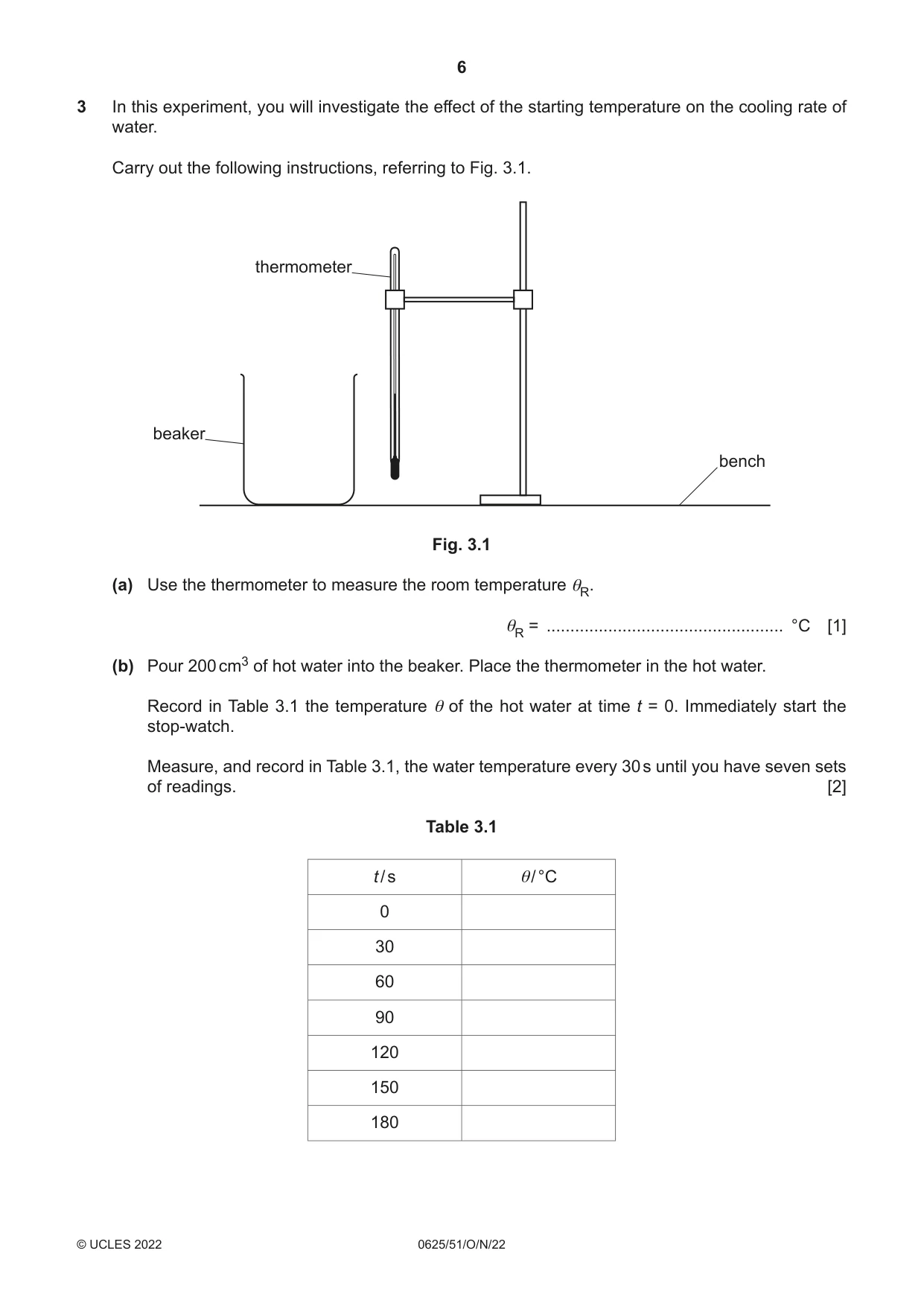
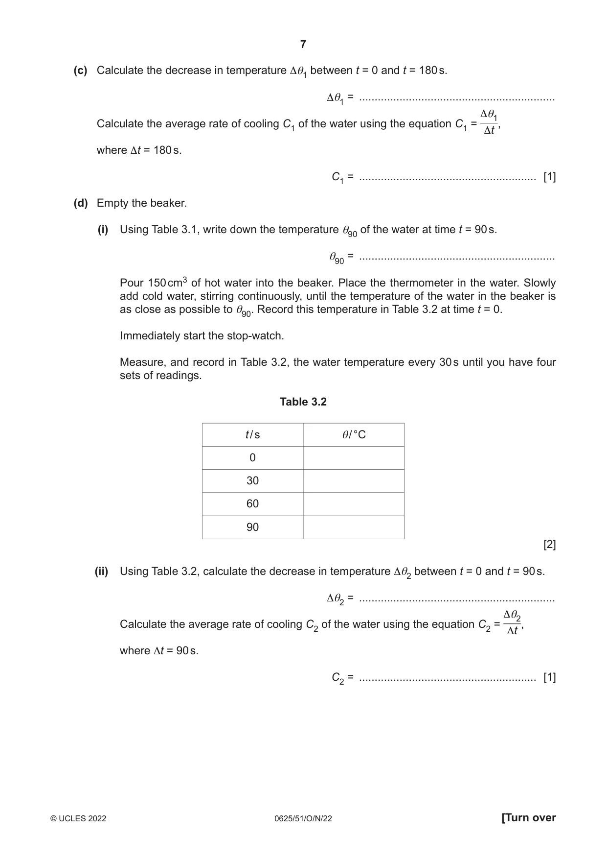
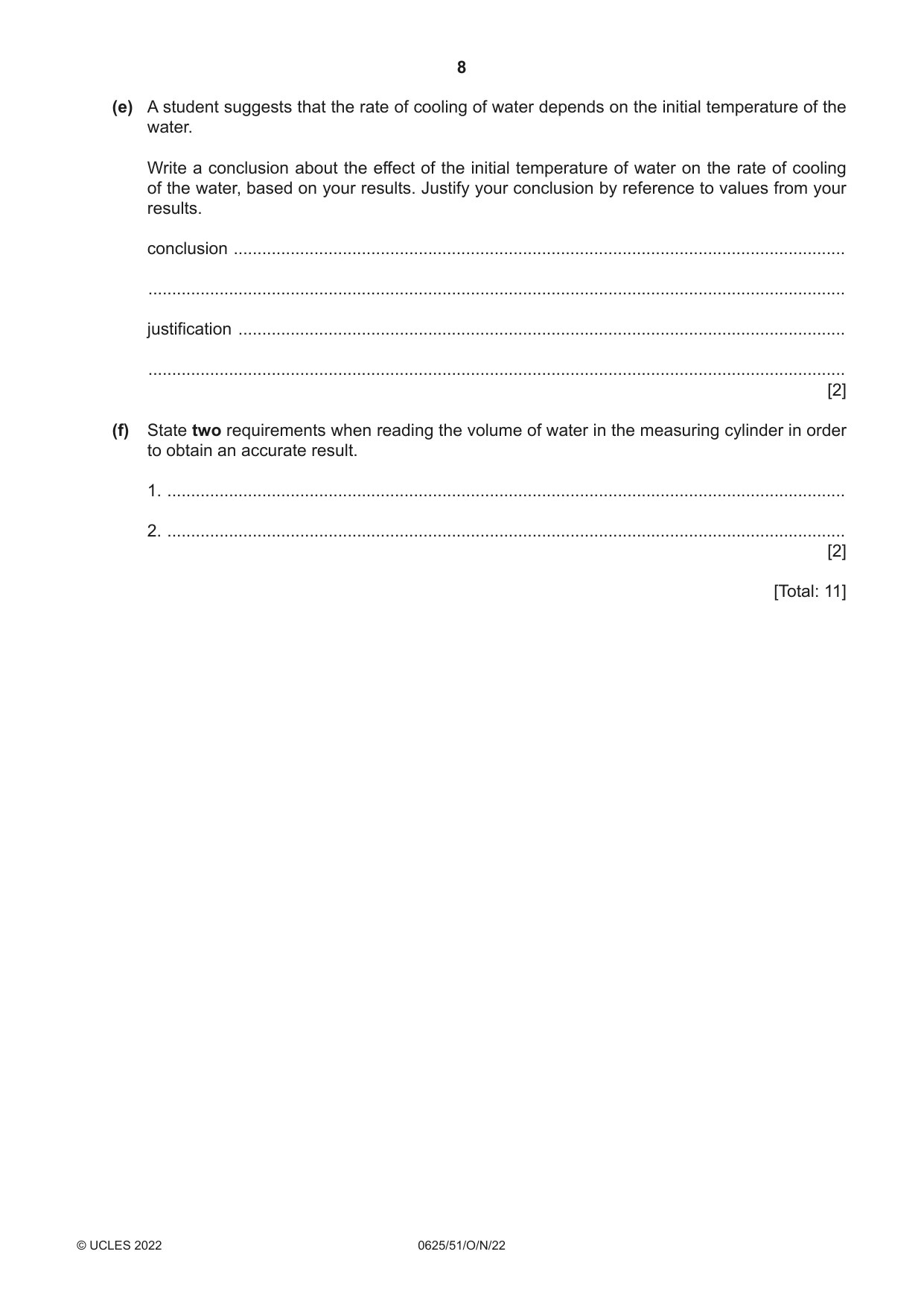
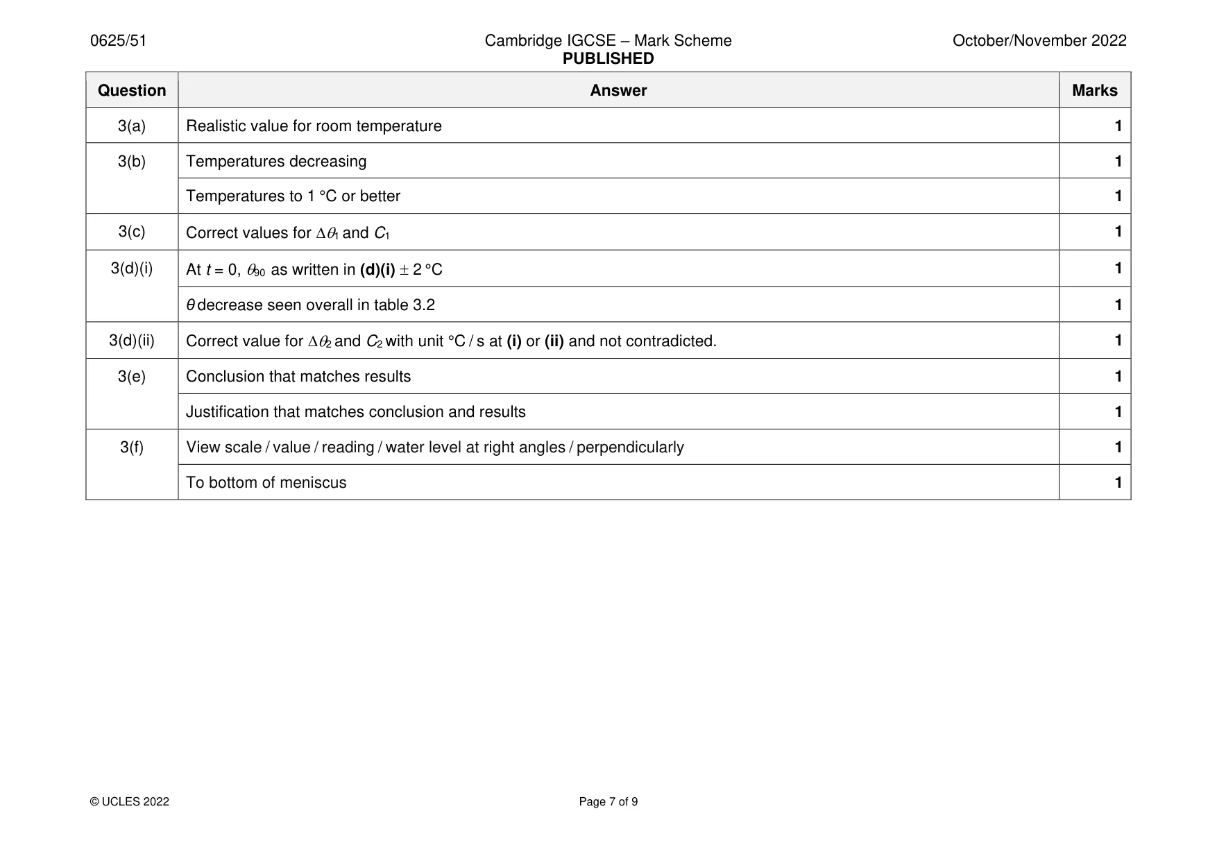
3 In this experiment, you will investigate the effect of the starting temperature on the cooling rate of water. Carry out the following instructions, referring to Fig. 3.1. thermometer beaker bench Fig. 3.1 (a) Use the thermometer to measure the room temperature θR. θR = .................................................. °C [1] (b) Pour 200 cm3 of hot water into the beaker. Place the thermometer in the hot water. Record in Table 3.1 the temperature θ of the hot water at time t = 0. Immediately start the stop-watch. Measure, and record in Table 3.1, the water temperature every 30 s until you have seven sets of readings. [2] Table 3.1 t / s θ/ °C 0 30 60 90 120 150 180 (c) Calculate the decrease in temperature Δθ1 between t = 0 and t = 180 s. Δθ1 = ............................................................... Δθ1 Calculate the average rate of cooling C1 of the water using the equation C1 = , Δt where Δt = 180 s. C1 = ......................................................... [1] (d) Empty the beaker. (i) Using Table 3.1, write down the temperature θ90 of the water at time t = 90 s. θ90 = ............................................................... Pour 150 cm3 of hot water into the beaker. Place the thermometer in the water. Slowly add cold water, stirring continuously, until the temperature of the water in the beaker is as close as possible to θ90. Record this temperature in Table 3.2 at time t = 0. Immediately start the stop-watch. Measure, and record in Table 3.2, the water temperature every 30 s until you have four sets of readings. Table 3.2 t / s θ/ °C 0 30 60 90 [2] (ii) Using Table 3.2, calculate the decrease in temperature Δθ2 between t = 0 and t = 90 s. Δθ2 = ............................................................... Δθ2 Calculate the average rate of cooling C2 of the water using the equation C2 = , Δt where Δt = 90 s. C2 = ......................................................... [1] (e) A student suggests that the rate of cooling of water depends on the initial temperature of the water. Write a conclusion about the effect of the initial temperature of water on the rate of cooling of the water, based on your results. Justify your conclusion by reference to values from your results. conclusion ................................................................................................................................. ................................................................................................................................................... justification ................................................................................................................................ ................................................................................................................................................... [2] (f) State two requirements when reading the volume of water in the measuring cylinder in order to obtain an accurate result. 1. ............................................................................................................................................... 2. ............................................................................................................................................... [2] [Total: 11]
Mark scheme: 3(a) Realistic value for room temperature 1 3(b) Temperatures decreasing 1 Temperatures to 1 °C or better 1 3(c) Correct values for 1 and C1 1 3(d)(i) At t = 0, 90 as written in (d)(i) 2 °C 1 θ decrease seen overall in table 3.2 1 3(d)(ii) Correct value for 2 and C2 with unit °C / s at (i) or (ii) and not contradicted. 1 3(e) Conclusion that matches results 1 Justification that matches conclusion and results 1 3(f) View scale / value / reading / water level at right angles / perpendicularly 1 To bottom of meniscus 1
Q4 · A student investigates the horizontal distance travelled by a metal ball after it rolls…
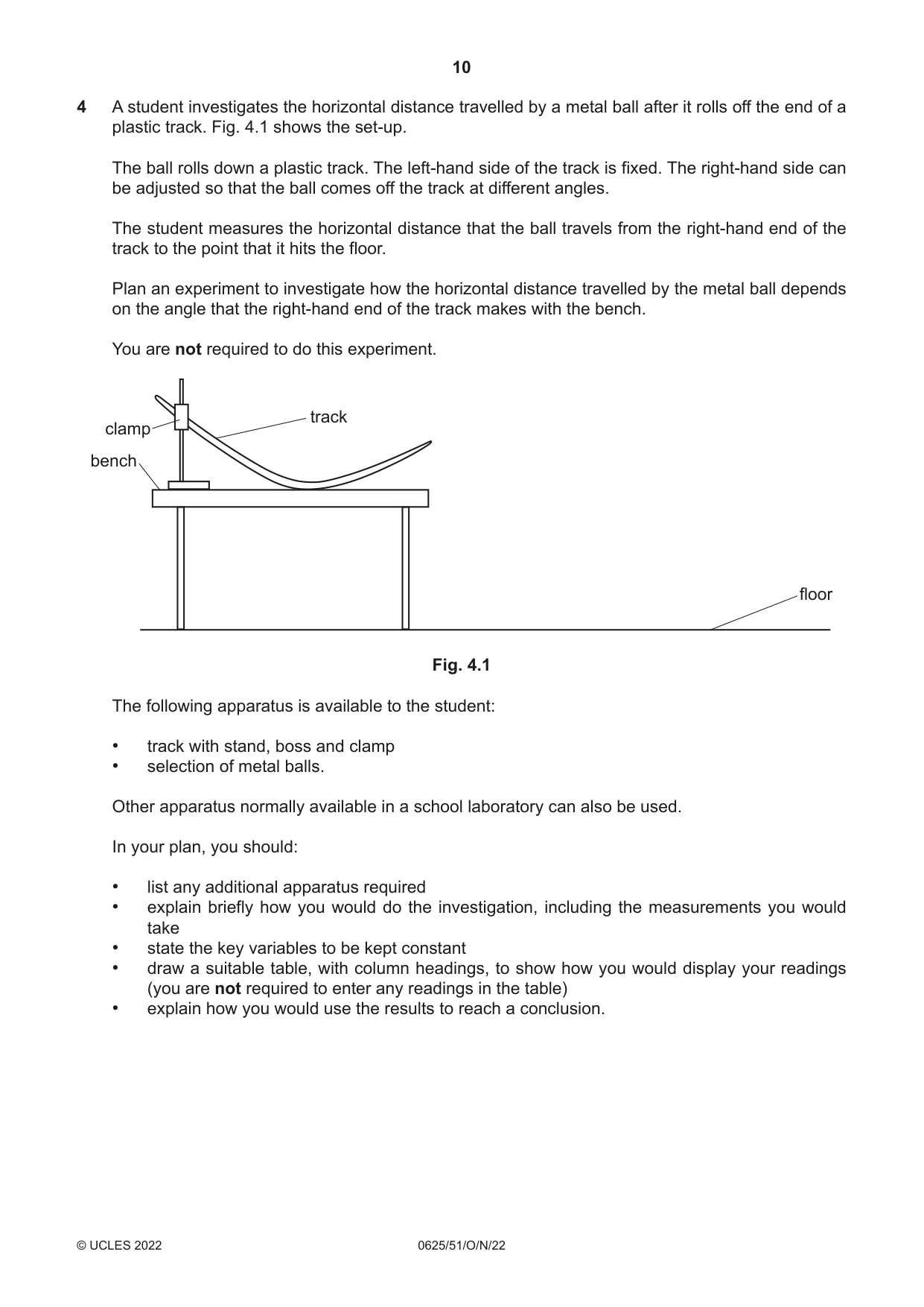
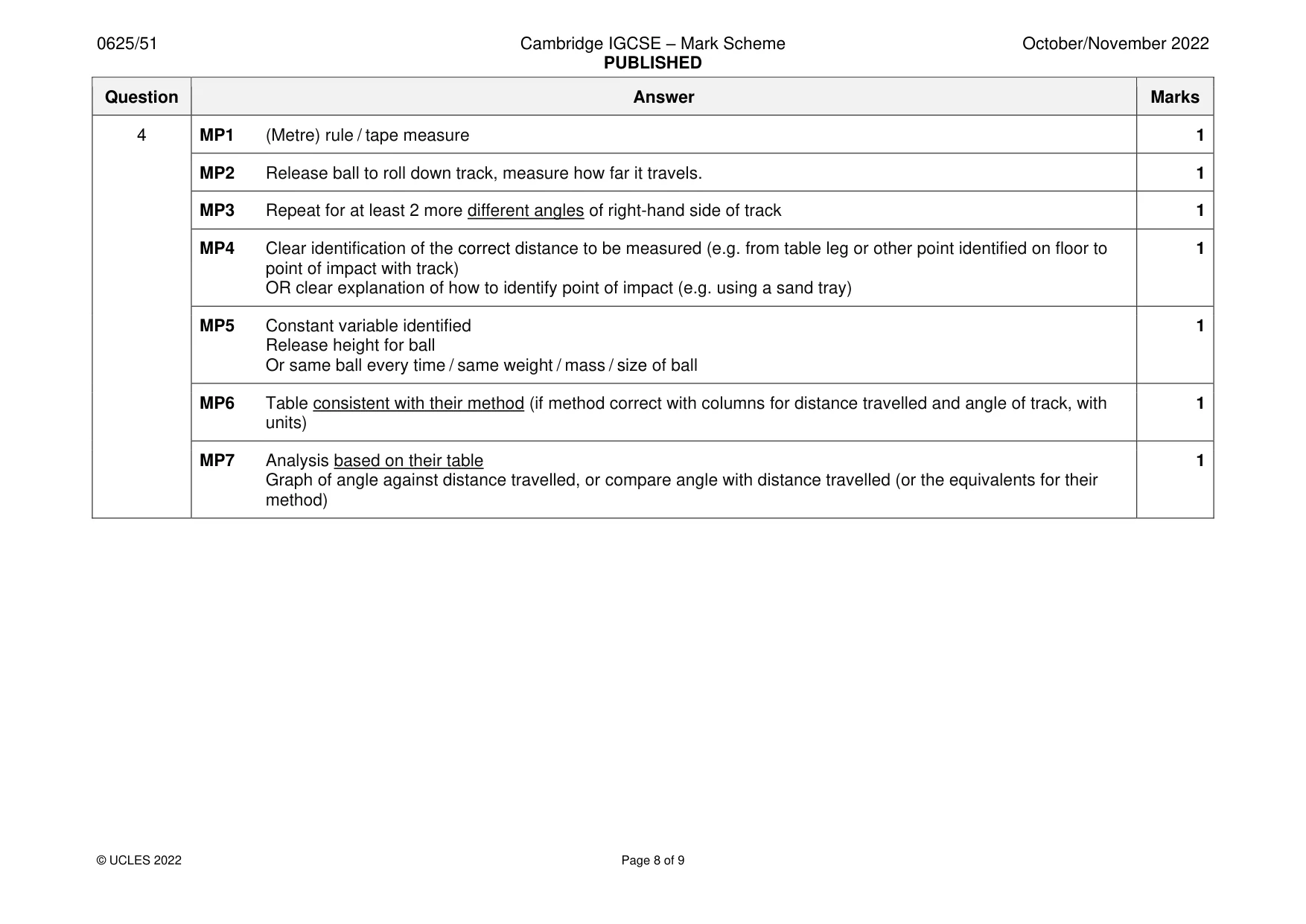
4 A student investigates the horizontal distance travelled by a metal ball after it rolls off the end of a plastic track. Fig. 4.1 shows the set-up. The ball rolls down a plastic track. The left-hand side of the track is fixed. The right-hand side can be adjusted so that the ball comes off the track at different angles. The student measures the horizontal distance that the ball travels from the right-hand end of the track to the point that it hits the floor. Plan an experiment to investigate how the horizontal distance travelled by the metal ball depends on the angle that the right-hand end of the track makes with the bench. You are not required to do this experiment. track clamp bench floor Fig. 4.1 The following apparatus is available to the student: • track with stand, boss and clamp • selection of metal balls. Other apparatus normally available in a school laboratory can also be used. In your plan, you should: • list any additional apparatus required • explain briefly how you would do the investigation, including the measurements you would take • state the key variables to be kept constant • draw a suitable table, with column headings, to show how you would display your readings (you are not required to enter any readings in the table) • explain how you would use the results to reach a conclusion. .......................................................................................................................................................... .......................................................................................................................................................... .......................................................................................................................................................... .......................................................................................................................................................... .......................................................................................................................................................... .......................................................................................................................................................... .......................................................................................................................................................... .......................................................................................................................................................... .......................................................................................................................................................... .......................................................................................................................................................... .......................................................................................................................................................... .......................................................................................................................................................... .......................................................................................................................................................... .......................................................................................................................................................... .......................................................................................................................................................... .......................................................................................................................................................... .................................................................................................................................................... [7]
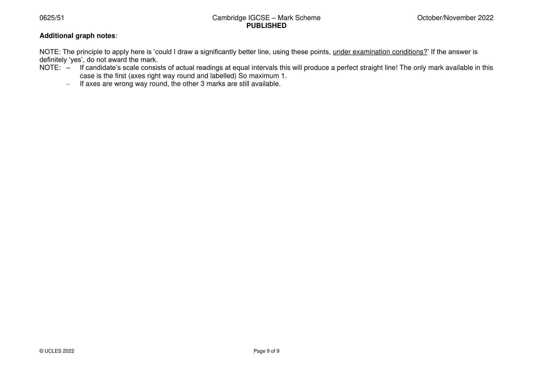
Mark scheme: 4 MP1 (Metre) rule / tape measure 1 MP2 Release ball to roll down track, measure how far it travels. 1 MP3 Repeat for at least 2 more different angles of right-hand side of track 1 MP4 Clear identification of the correct distance to be measured (e.g. from table leg or other point identified on floor to 1 point of impact with track) OR clear explanation of how to identify point of impact (e.g. using a sand tray) MP5 Constant variable identified 1 Release height for ball Or same ball every time / same weight / mass / size of ball MP6 Table consistent with their method (if method correct with columns for distance travelled and angle of track, with 1 units) MP7 Analysis based on their table 1 Graph of angle against distance travelled, or compare angle with distance travelled (or the equivalents for their method) Additional graph notes: NOTE: The principle to apply here is ‘could I draw a significantly better line, using these points, under examination conditions?’ If the answer is definitely ‘yes’, do not award the mark. NOTE: – If candidate’s scale consists of actual readings at equal intervals this will produce a perfect straight line! The only mark available in this case is the first (axes right way round and labelled) So maximum 1. – If axes are wrong way round, the other 3 marks are still available.
What was in this paper
The subtopics covered by these 4 questions, and how many questions each got. Open one in a new tab to see every Cambridge question on it.
What you needed in this session
Cambridge’s own grade thresholds for 2022 Oct/Nov, Paper 5 · Variant 1. A higher threshold means an easier paper — the bar moves with how the cohort did.