Cambridge IGCSE Physics 0625 — 2020 May/June Paper 6 · Variant 3
0625/63/M/J/20 · 4 questions · 40 marks · ≈45 min
The question paper and its mark scheme, free to read here and free to download. This is Cambridge’s own paper, exactly as it was sat.
Question paper16 pages
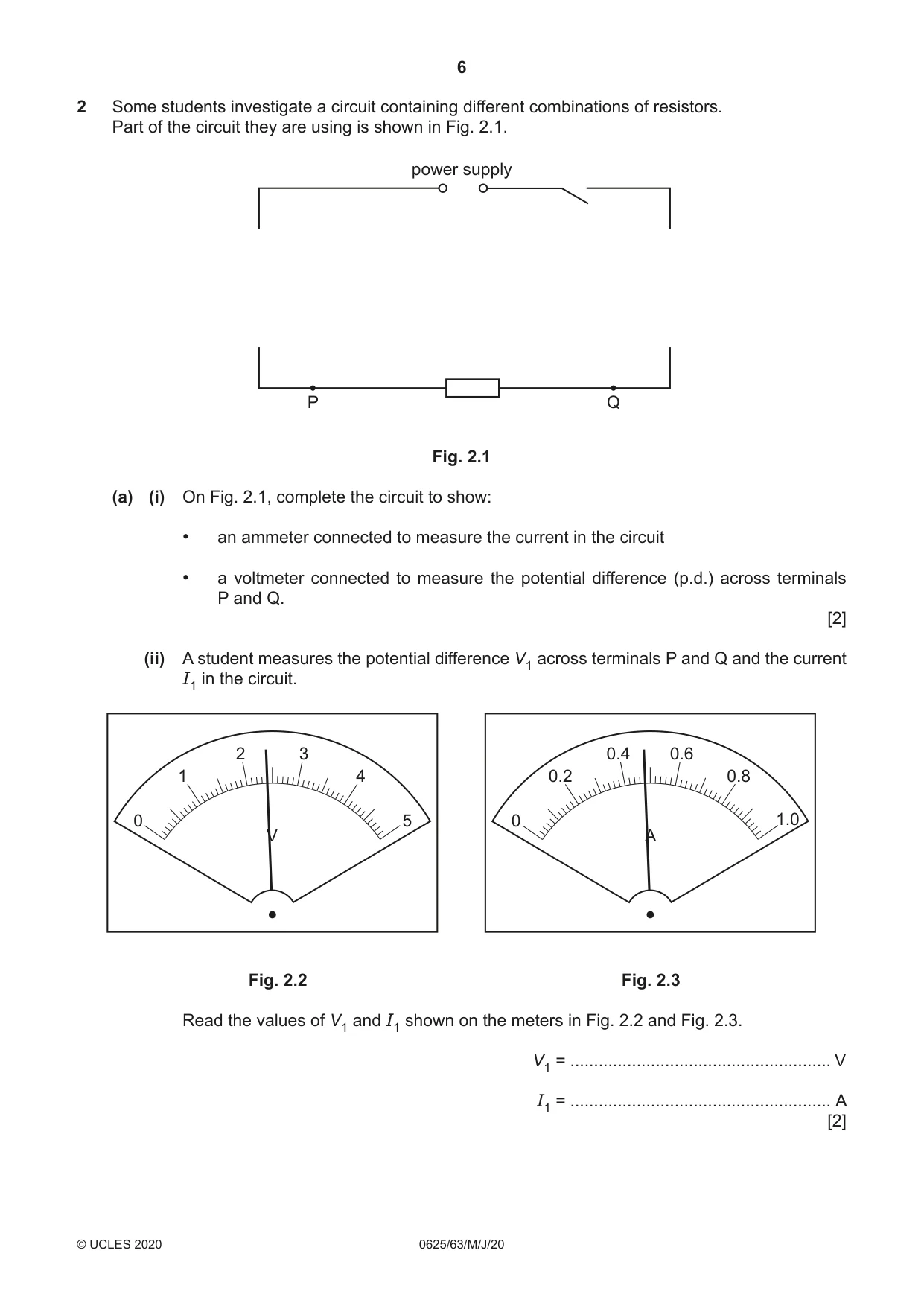
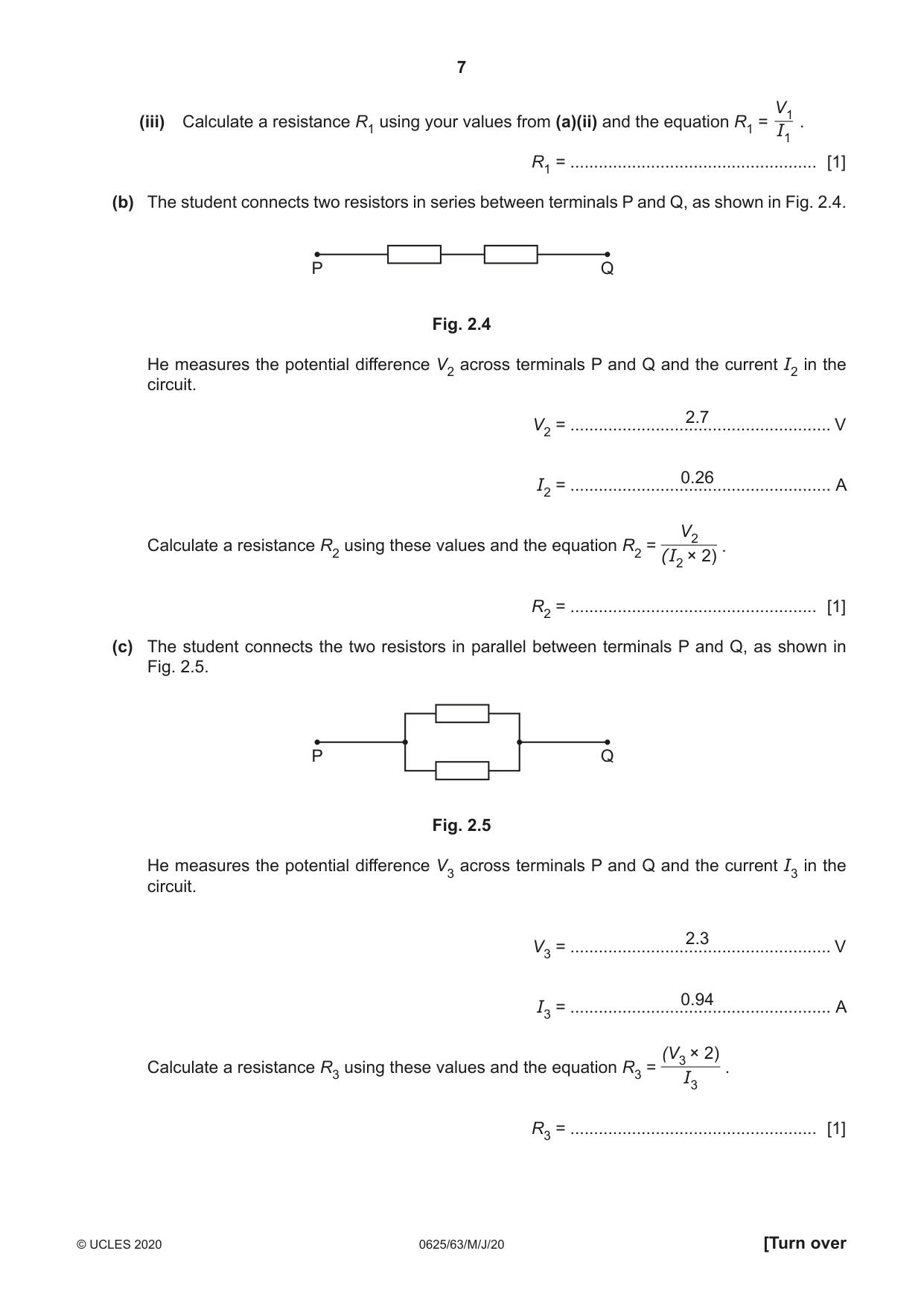
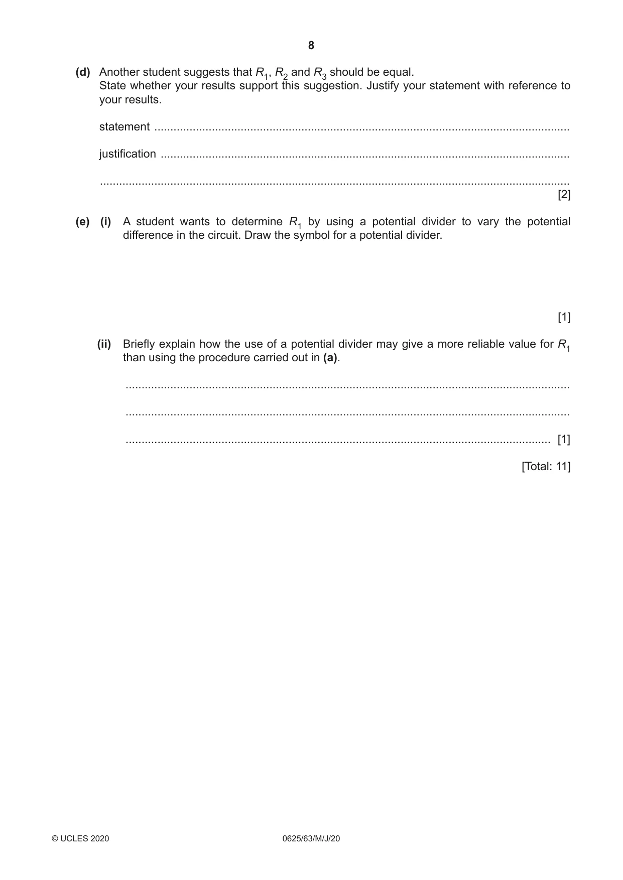



Mark scheme8 pages
Answers below. Sit the paper first if you are practising.
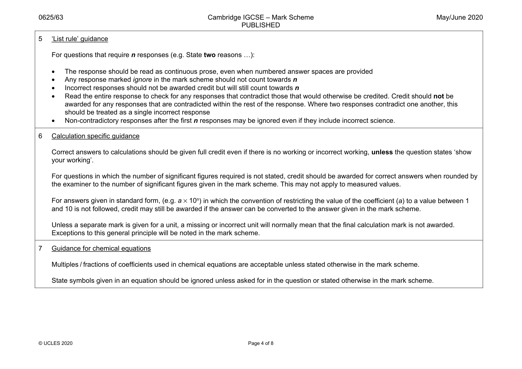
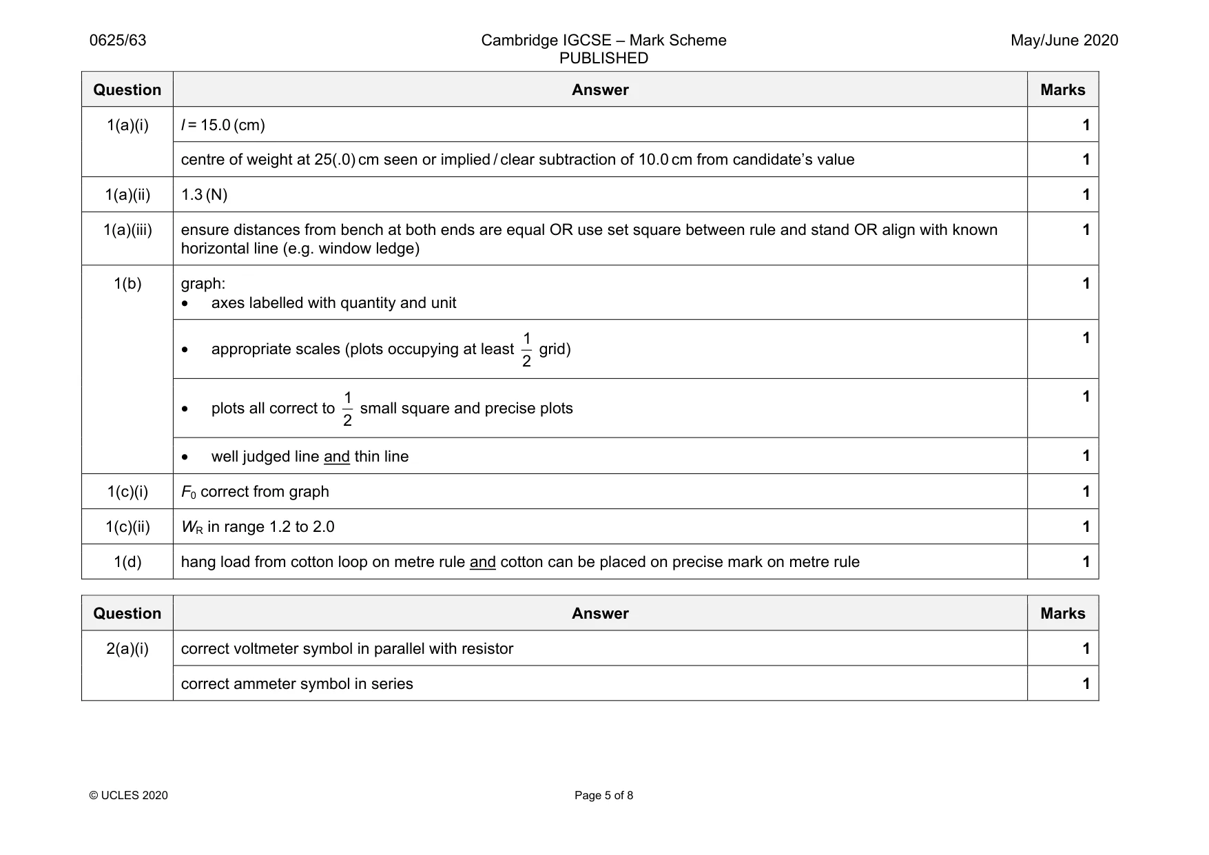
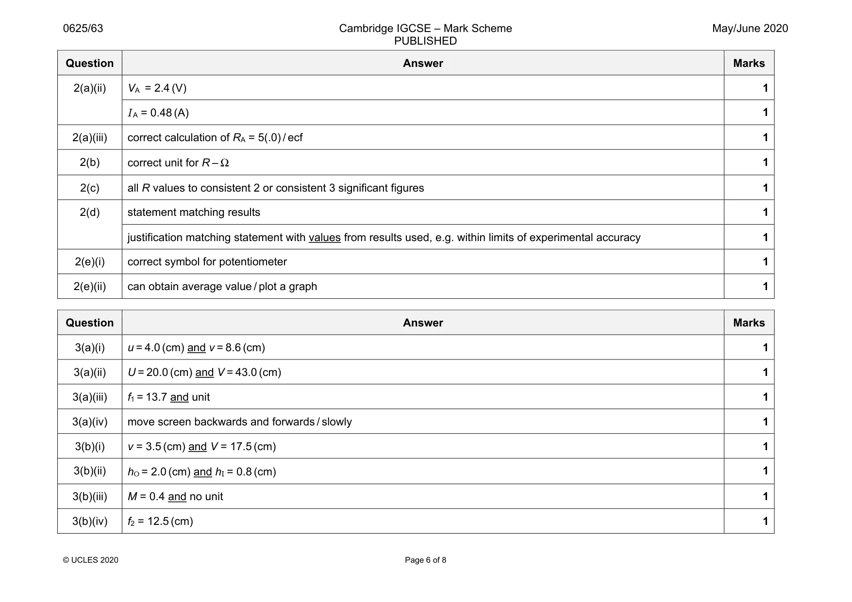
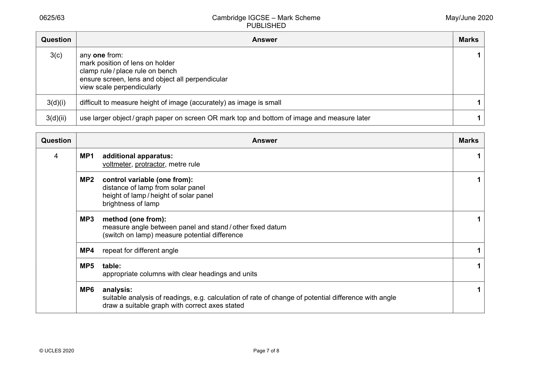
Questions as text
Q1 · A student determines the weight of a metre rule
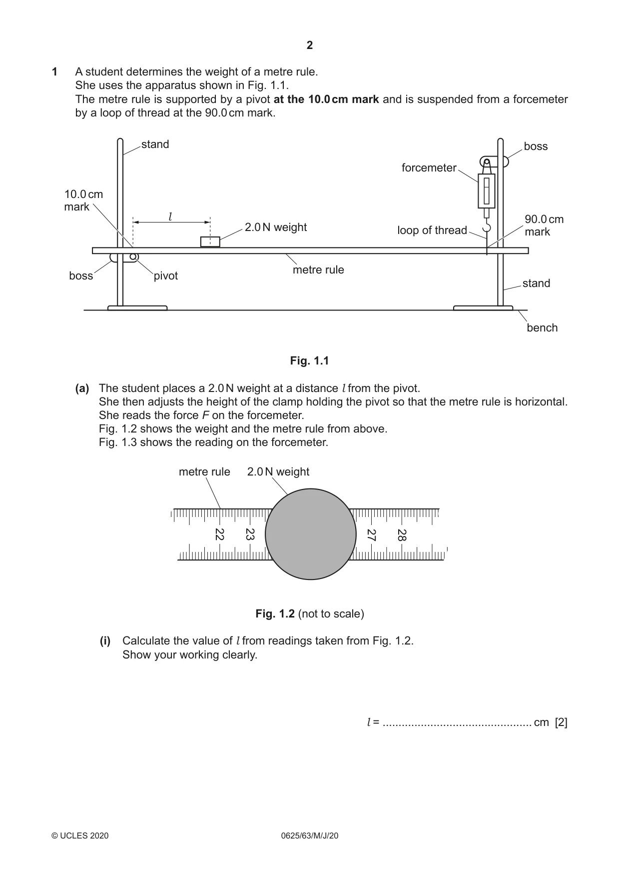
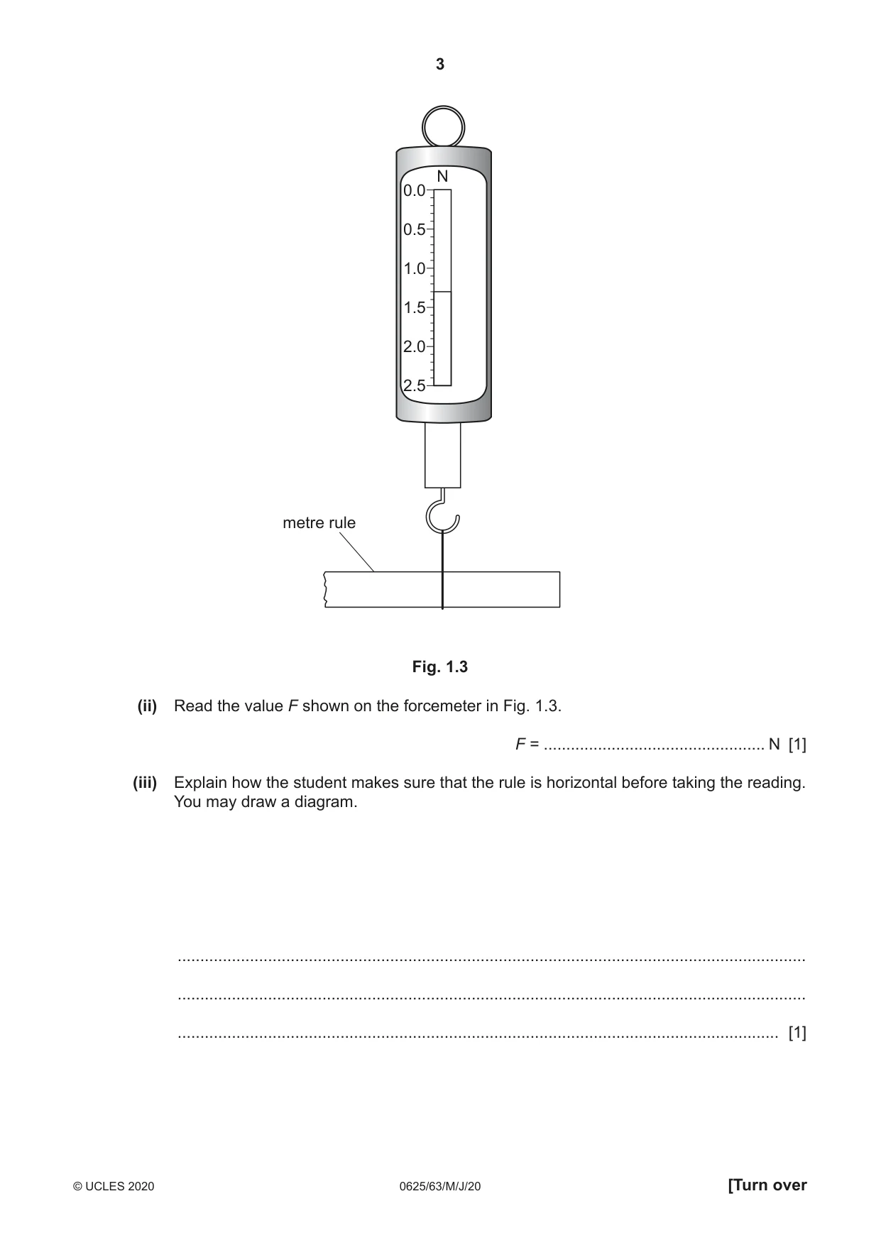
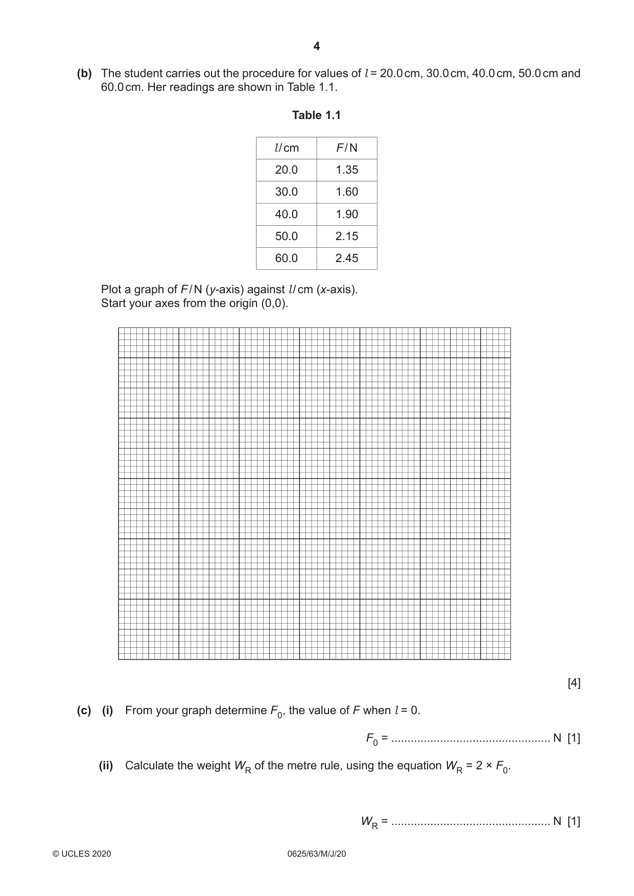
1 A student determines the weight of a metre rule. She uses the apparatus shown in Fig. 1.1. The metre rule is supported by a pivot at the 10.0 cm mark and is suspended from a forcemeter by a loop of thread at the 90.0 cm mark. stand boss forcemeter 10.0 cm mark l 90.0 cm 2.0 N weight loop of thread mark metre rule boss pivot stand bench Fig. 1.1 (a) The student places a 2.0 N weight at a distance l from the pivot. She then adjusts the height of the clamp holding the pivot so that the metre rule is horizontal. She reads the force F on the forcemeter. Fig. 1.2 shows the weight and the metre rule from above. Fig. 1.3 shows the reading on the forcemeter. metre rule 2.0 N weight 22 23 27 28 Fig. 1.2 (not to scale) (i) Calculate the value of l from readings taken from Fig. 1.2. Show your working clearly. l = ............................................... cm [2] N 0.0 0.5 1.0 1.5 2.0 2.5 metre rule Fig. 1.3 (ii) Read the value F shown on the forcemeter in Fig. 1.3. F = ................................................. N [1] (iii) Explain how the student makes sure that the rule is horizontal before taking the reading. You may draw a diagram. ........................................................................................................................................... ........................................................................................................................................... ..................................................................................................................................... [1] (b) The student carries out the procedure for values of l = 20.0 cm, 30.0 cm, 40.0 cm, 50.0 cm and 60.0 cm. Her readings are shown in Table 1.1. Table 1.1 l / cm F / N 20.0 1.35 30.0 1.60 40.0 1.90 50.0 2.15 60.0 2.45 Plot a graph of F / N (y-axis) against l / cm (x-axis). Start your axes from the origin (0,0). [4] (c) (i) From your graph determine F0, the value of F when l = 0. F0 = ................................................. N [1] (ii) Calculate the weight WR of the metre rule, using the equation WR = 2 × F0. WR = ................................................. N [1] (d) Another student carrying out this experiment finds it difficult to be sure that he has placed the centre of the 2.0 N weight on the metre rule at the correct value of l. Suggest a more precise method of applying a 2.0 N load to the metre rule in this experiment. Explain why this method is an improvement. ................................................................................................................................................... ................................................................................................................................................... ............................................................................................................................................. [1] [Total: 11]
Mark scheme: 1(a)(i) l = 15.0 (cm) 1 centre of weight at 25(.0) cm seen or implied / clear subtraction of 10.0 cm from candidate’s value 1 1(a)(ii) 1.3 (N) 1 1(a)(iii) ensure distances from bench at both ends are equal OR use set square between rule and stand OR align with known horizontal line (e.g. window ledge) 1 1(b) graph: • axes labelled with quantity and unit 1 • appropriate scales (plots occupying at least 1 2 grid) 1 • plots all correct to 1 2 small square and precise plots 1 • well judged line and thin line 1 1(c)(i) F0 correct from graph 1 1(c)(ii) WR in range 1.2 to 2.0 1 1(d) hang load from cotton loop on metre rule and cotton can be placed on precise mark on metre rule 1
Q2 · Some students investigate a circuit containing different combinations of resistors
2 Some students investigate a circuit containing different combinations of resistors. Part of the circuit they are using is shown in Fig. 2.1. power supply P Q Fig. 2.1 (a) (i) On Fig. 2.1, complete the circuit to show: • an ammeter connected to measure the current in the circuit • a voltmeter connected to measure the potential difference (p.d.) across terminals P and Q. [2] (ii) A student measures the potential difference V1 across terminals P and Q and the current I1 in the circuit. 2 3 0.4 0.6 1 4 0.2 0.8 0 5 0 1.0 V A Fig. 2.2 Fig. 2.3 Read the values of V1 and I1 shown on the meters in Fig. 2.2 and Fig. 2.3. V1 = ....................................................... V I1 = ....................................................... A [2] V1 (iii) Calculate a resistance R1 using your values from (a)(ii) and the equation R1 = . I1 R1 = .................................................... [1] (b) The student connects two resistors in series between terminals P and Q, as shown in Fig. 2.4. P Q Fig. 2.4 He measures the potential difference V2 across terminals P and Q and the current I2 in the circuit. 2.7 V2 = ....................................................... V 0.26 I2 = ....................................................... A V2 Calculate a resistance R2 using these values and the equation R2 = . (I2 × 2) R2 = .................................................... [1] (c) The student connects the two resistors in parallel between terminals P and Q, as shown in Fig. 2.5. P Q Fig. 2.5 He measures the potential difference V3 across terminals P and Q and the current I3 in the circuit. 2.3 V3 = ....................................................... V 0.94 I3 = ....................................................... A (V3 × 2) Calculate a resistance R3 using these values and the equation R3 = . I3 R3 = .................................................... [1] (d) Another student suggests that R1, R2 and R3 should be equal. State whether your results support this suggestion. Justify your statement with reference to your results. statement .................................................................................................................................. justification ................................................................................................................................ ................................................................................................................................................... [2] (e) (i) A student wants to determine R1 by using a potential divider to vary the potential difference in the circuit. Draw the symbol for a potential divider. [1] (ii) Briefly explain how the use of a potential divider may give a more reliable value for R1 than using the procedure carried out in (a). ........................................................................................................................................... ........................................................................................................................................... ..................................................................................................................................... [1] [Total: 11]
Mark scheme: 2(a)(i) correct voltmeter symbol in parallel with resistor 1 correct ammeter symbol in series 1 Question Answer Marks 2(a)(ii) VA = 2.4 (V) 1 I A = 0.48 (A) 1 2(a)(iii) correct calculation of RA = 5(.0) / ecf 1 2(b) correct unit for R – Ω 1 2(c) all R values to consistent 2 or consistent 3 significant figures 1 2(d) statement matching results 1 justification matching statement with values from results used, e.g. within limits of experimental accuracy 1 2(e)(i) correct symbol for potentiometer 1 2(e)(ii) can obtain average value / plot a graph 1
Q3 · A student determines the focal length of a converging lens
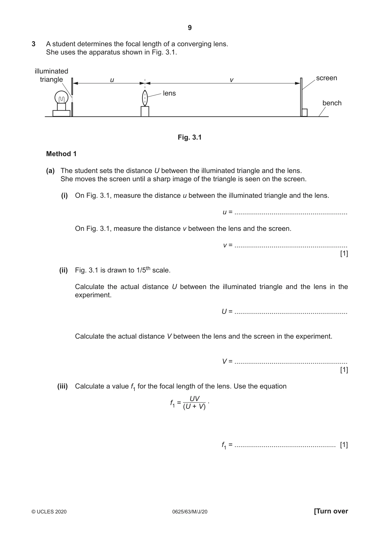
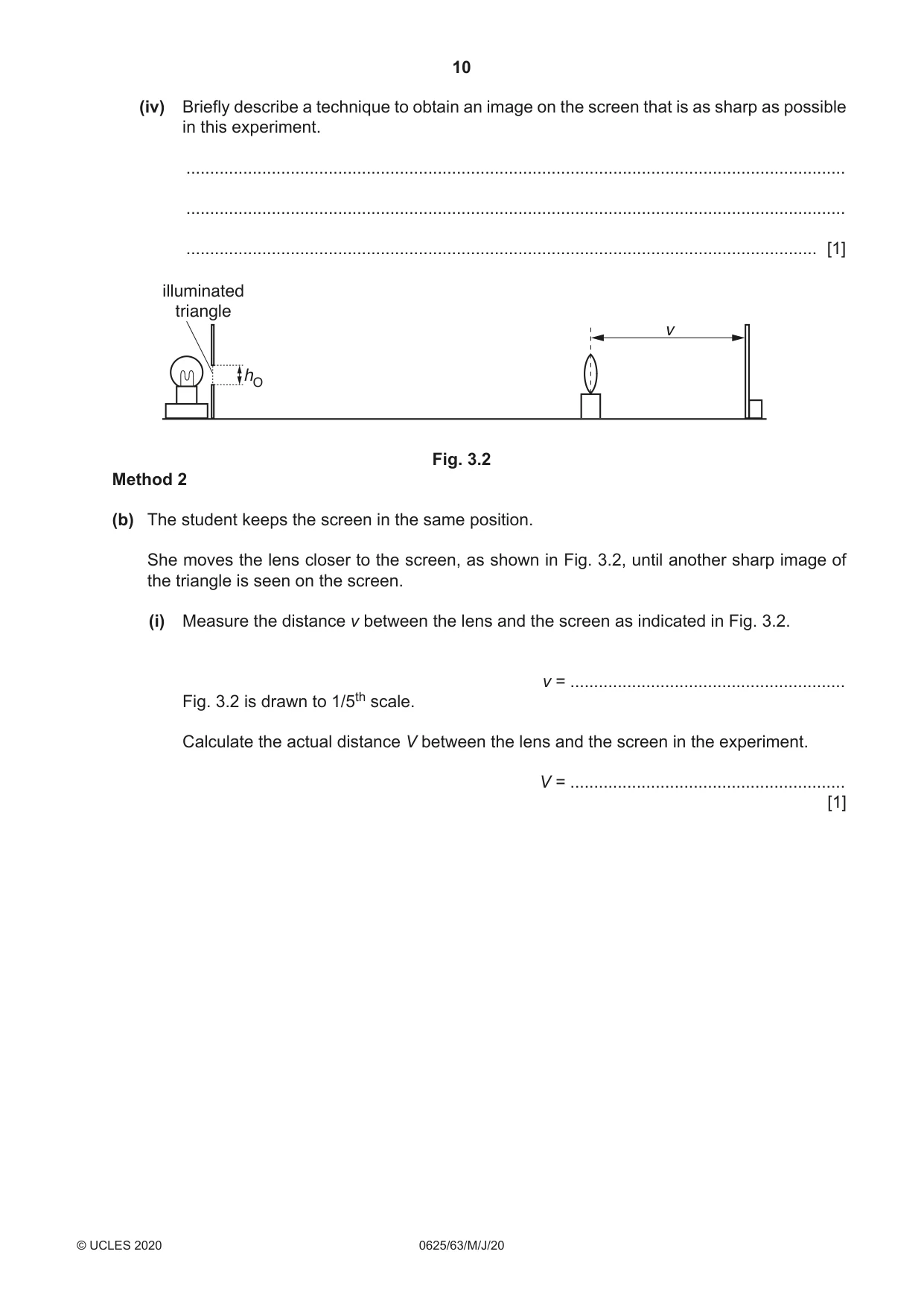
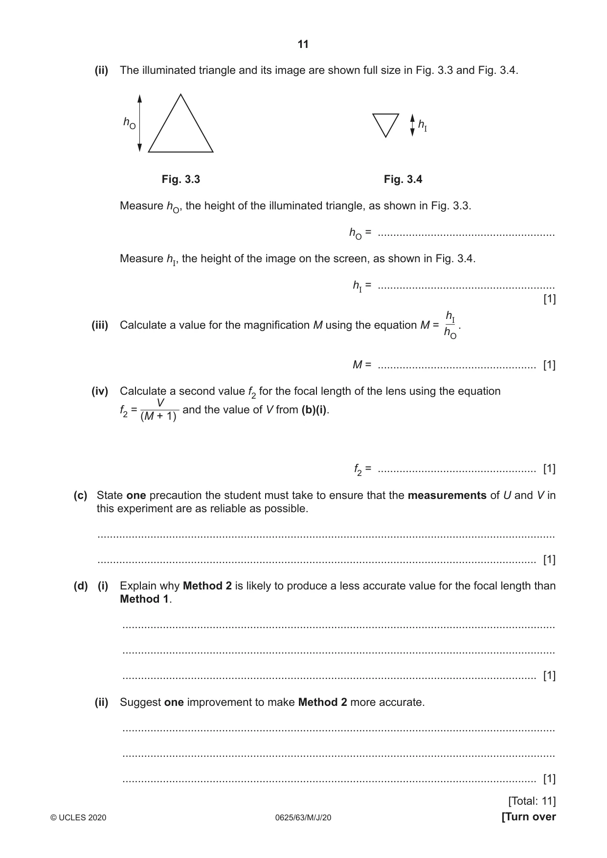
3 A student determines the focal length of a converging lens. She uses the apparatus shown in Fig. 3.1. illuminated triangle u v screen lens bench Fig. 3.1 Method 1 (a) The student sets the distance U between the illuminated triangle and the lens. She moves the screen until a sharp image of the triangle is seen on the screen. (i) On Fig. 3.1, measure the distance u between the illuminated triangle and the lens. u = .......................................................... On Fig. 3.1, measure the distance v between the lens and the screen. v = .......................................................... [1] (ii) Fig. 3.1 is drawn to 1/5th scale. Calculate the actual distance U between the illuminated triangle and the lens in the experiment. U = .......................................................... Calculate the actual distance V between the lens and the screen in the experiment. V = .......................................................... [1] (iii) Calculate a value f1 for the focal length of the lens. Use the equation UV . f1 = (U + V) f1 = .................................................... [1] (iv) Briefly describe a technique to obtain an image on the screen that is as sharp as possible in this experiment. ........................................................................................................................................... ........................................................................................................................................... ..................................................................................................................................... [1] illuminated triangle v hO Fig. 3.2 Method 2 (b) The student keeps the screen in the same position. She moves the lens closer to the screen, as shown in Fig. 3.2, until another sharp image of the triangle is seen on the screen. (i) Measure the distance v between the lens and the screen as indicated in Fig. 3.2. v = .......................................................... Fig. 3.2 is drawn to 1/5th scale. Calculate the actual distance V between the lens and the screen in the experiment. V = .......................................................... [1] (ii) The illuminated triangle and its image are shown full size in Fig. 3.3 and Fig. 3.4. hO hI Fig. 3.3 Fig. 3.4 Measure hO, the height of the illuminated triangle, as shown in Fig. 3.3. hO = ......................................................... Measure hI, the height of the image on the screen, as shown in Fig. 3.4. hI = ......................................................... [1] hI (iii) Calculate a value for the magnification M using the equation M = . hO M = ................................................... [1] (iv) Calculate a second value f2 for the focal length of the lens using the equation V f2 = and the value of V from (b)(i). (M + 1) f2 = ................................................... [1] (c) State one precaution the student must take to ensure that the measurements of U and V in this experiment are as reliable as possible. ................................................................................................................................................... ............................................................................................................................................. [1] (d) (i) Explain why Method 2 is likely to produce a less accurate value for the focal length than Method 1. ........................................................................................................................................... ........................................................................................................................................... ..................................................................................................................................... [1] (ii) Suggest one improvement to make Method 2 more accurate. ........................................................................................................................................... ........................................................................................................................................... ..................................................................................................................................... [1] [Total: 11]
Mark scheme: 3(a)(i) u = 4.0 (cm) and v = 8.6 (cm) 1 3(a)(ii) U = 20.0 (cm) and V = 43.0 (cm) 1 3(a)(iii) f1 = 13.7 and unit 1 3(a)(iv) move screen backwards and forwards / slowly 1 3(b)(i) v = 3.5 (cm) and V = 17.5 (cm) 1 3(b)(ii) hO = 2.0 (cm) and hI = 0.8 (cm) 1 3(b)(iii) M = 0.4 and no unit 1 3(b)(iv) f2 = 12.5 (cm) 1 Question Answer Marks 3(c) any one from: mark position of lens on holder clamp rule / place rule on bench ensure screen, lens and object all perpendicular view scale perpendicularly 1 3(d)(i) difficult to measure height of image (accurately) as image is small 1 3(d)(ii) use larger object / graph paper on screen OR mark top and bottom of image and measure later 1
Q4 · A student investigates the factors affecting the electrical output of a solar cell
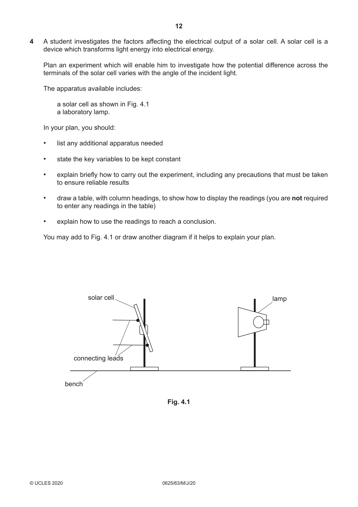
4 A student investigates the factors affecting the electrical output of a solar cell. A solar cell is a device which transforms light energy into electrical energy. Plan an experiment which will enable him to investigate how the potential difference across the terminals of the solar cell varies with the angle of the incident light. The apparatus available includes: a solar cell as shown in Fig. 4.1 a laboratory lamp. In your plan, you should: • list any additional apparatus needed • state the key variables to be kept constant • explain briefly how to carry out the experiment, including any precautions that must be taken to ensure reliable results • draw a table, with column headings, to show how to display the readings (you are not required to enter any readings in the table) • explain how to use the readings to reach a conclusion. You may add to Fig. 4.1 or draw another diagram if it helps to explain your plan. solar cell lamp connecting leads bench Fig. 4.1 .................................................................................................................................................................. .................................................................................................................................................................. .................................................................................................................................................................. .................................................................................................................................................................. .................................................................................................................................................................. .................................................................................................................................................................. .................................................................................................................................................................. .................................................................................................................................................................. .................................................................................................................................................................. .................................................................................................................................................................. .................................................................................................................................................................. .................................................................................................................................................................. .................................................................................................................................................................. .................................................................................................................................................................. .................................................................................................................................................................. .................................................................................................................................................................. .................................................................................................................................................................. .................................................................................................................................................................. .................................................................................................................................................................. .................................................................................................................................................................. .................................................................................................................................................................. ............................................................................................................................................................ [7] [Total: 7]
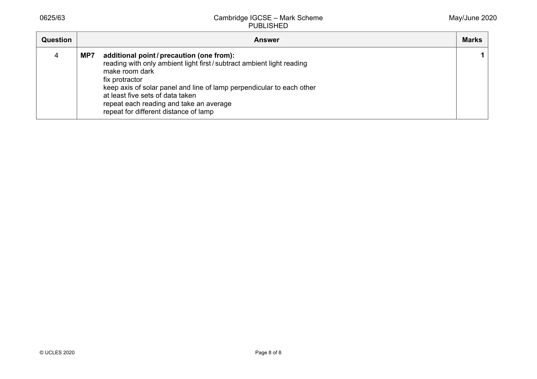
Mark scheme: 4 MP1 additional apparatus: voltmeter, protractor, metre rule 1 MP2 control variable (one from): distance of lamp from solar panel height of lamp / height of solar panel brightness of lamp 1 MP3 method (one from): measure angle between panel and stand / other fixed datum (switch on lamp) measure potential difference 1 MP4 repeat for different angle 1 MP5 table: appropriate columns with clear headings and units 1 MP6 analysis: suitable analysis of readings, e.g. calculation of rate of change of potential difference with angle draw a suitable graph with correct axes stated 1 Question Answer Marks 4 MP7 additional point / precaution (one from): reading with only ambient light first / subtract ambient light reading make room dark fix protractor keep axis of solar panel and line of lamp perpendicular to each other at least five sets of data taken repeat each reading and take an average repeat for different distance of lamp 1
What was in this paper
The subtopics covered by these 4 questions, and how many questions each got. Open one in a new tab to see every Cambridge question on it.