Cambridge IGCSE Physics 0625 — 2010 May/June Paper 5 · Variant 1
0625/51/M/J/10 · 4 questions · 40 marks · ≈45 min
The question paper and its mark scheme, free to read here and free to download. This is Cambridge’s own paper, exactly as it was sat.
Question paper12 pages

Mark scheme3 pages
Answers below. Sit the paper first if you are practising.
Questions as text
Q1 · In this experiment, you are to investigate the stretching of springs
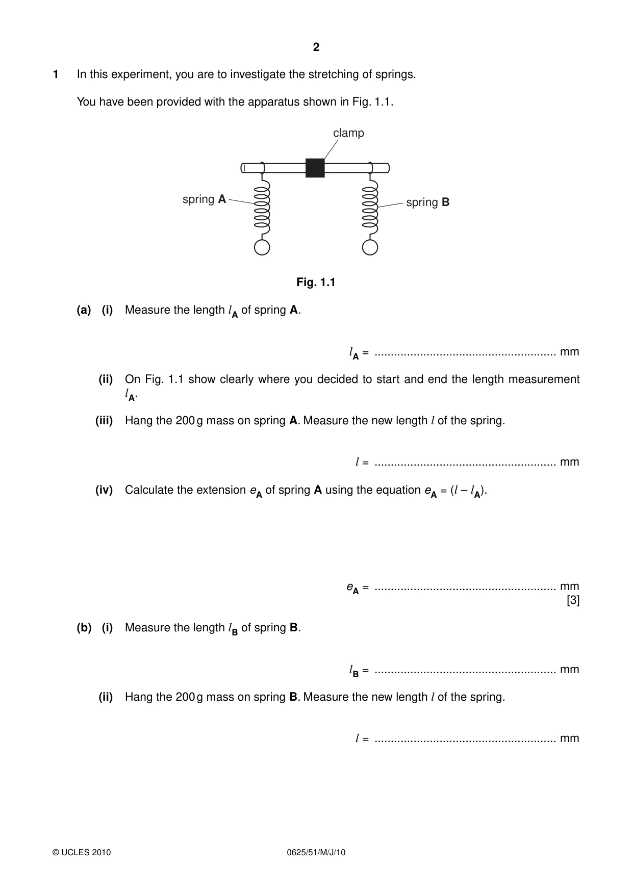
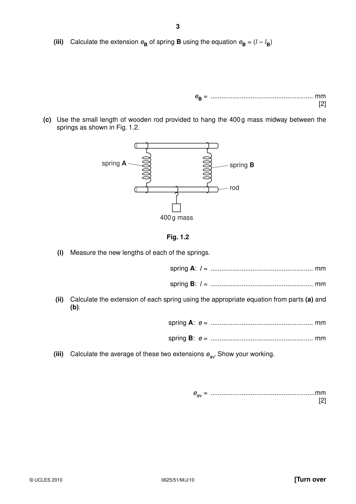
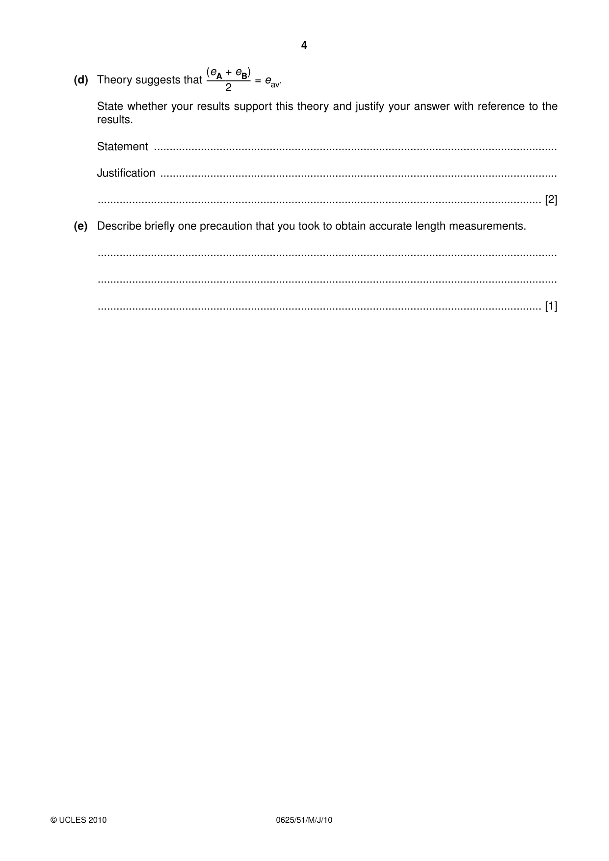
1 In this experiment, you are to investigate the stretching of springs. You have been provided with the apparatus shown in Fig. 1.1. clamp spring A spring B Fig. 1.1 (a) (i) Measure the length lA of spring A. lA = ........................................................ mm (ii) On Fig. 1.1 show clearly where you decided to start and end the length measurement lA. (iii) Hang the 200 g mass on spring A. Measure the new length l of the spring. l = ........................................................ mm (iv) Calculate the extension eA of spring A using the equation eA = (l – lA). eA = ........................................................ mm [3] (b) (i) Measure the length lB of spring B. lB = ........................................................ mm (ii) Hang the 200 g mass on spring B. Measure the new length l of the spring. l = ........................................................ mm (iii) Calculate the extension eB of spring B using the equation eB = (l – lB) eB = ........................................................ mm [2] (c) Use the small length of wooden rod provided to hang the 400 g mass midway between the springs as shown in Fig. 1.2. spring A spring B rod 400 g mass Fig. 1.2 (i) Measure the new lengths of each of the springs. spring A: l = ........................................................ mm spring B: l = ........................................................ mm (ii) Calculate the extension of each spring using the appropriate equation from parts (a) and (b). spring A: e = ........................................................ mm spring B: e = ........................................................ mm (iii) Calculate the average of these two extensions eav. Show your working. eav = .........................................................mm [2] (eA + eB) (d) Theory suggests that ––––––– = eav. 2 State whether your results support this theory and justify your answer with reference to the results. Statement ................................................................................................................................. Justification ............................................................................................................................... .............................................................................................................................................. [2] (e) Describe briefly one precaution that you took to obtain accurate length measurements. ................................................................................................................................................... ................................................................................................................................................... .............................................................................................................................................. [1]
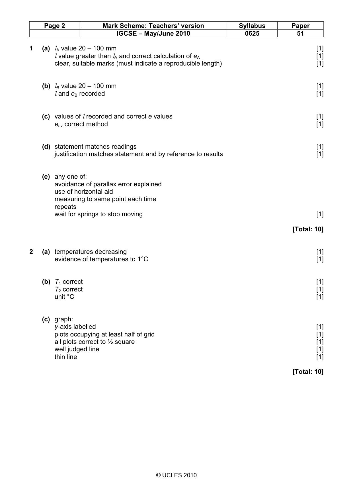
Mark scheme: 1 (a) lA value 20 – 100 mm [1] l value greater than lA and correct calculation of eA [1] clear, suitable marks (must indicate a reproducible length) [1] (b) lB value 20 – 100 mm [1] l and eB recorded [1] (c) values of l recorded and correct e values [1] eav correct method [1] (d) statement matches readings [1] justification matches statement and by reference to results [1] (e) any one of: avoidance of parallax error explained use of horizontal aid measuring to same point each time repeats wait for springs to stop moving [1] [Total: 10]
More questions on Physical quantities and measurement techniques
Q2 · In this experiment, you are to investigate the cooling of water
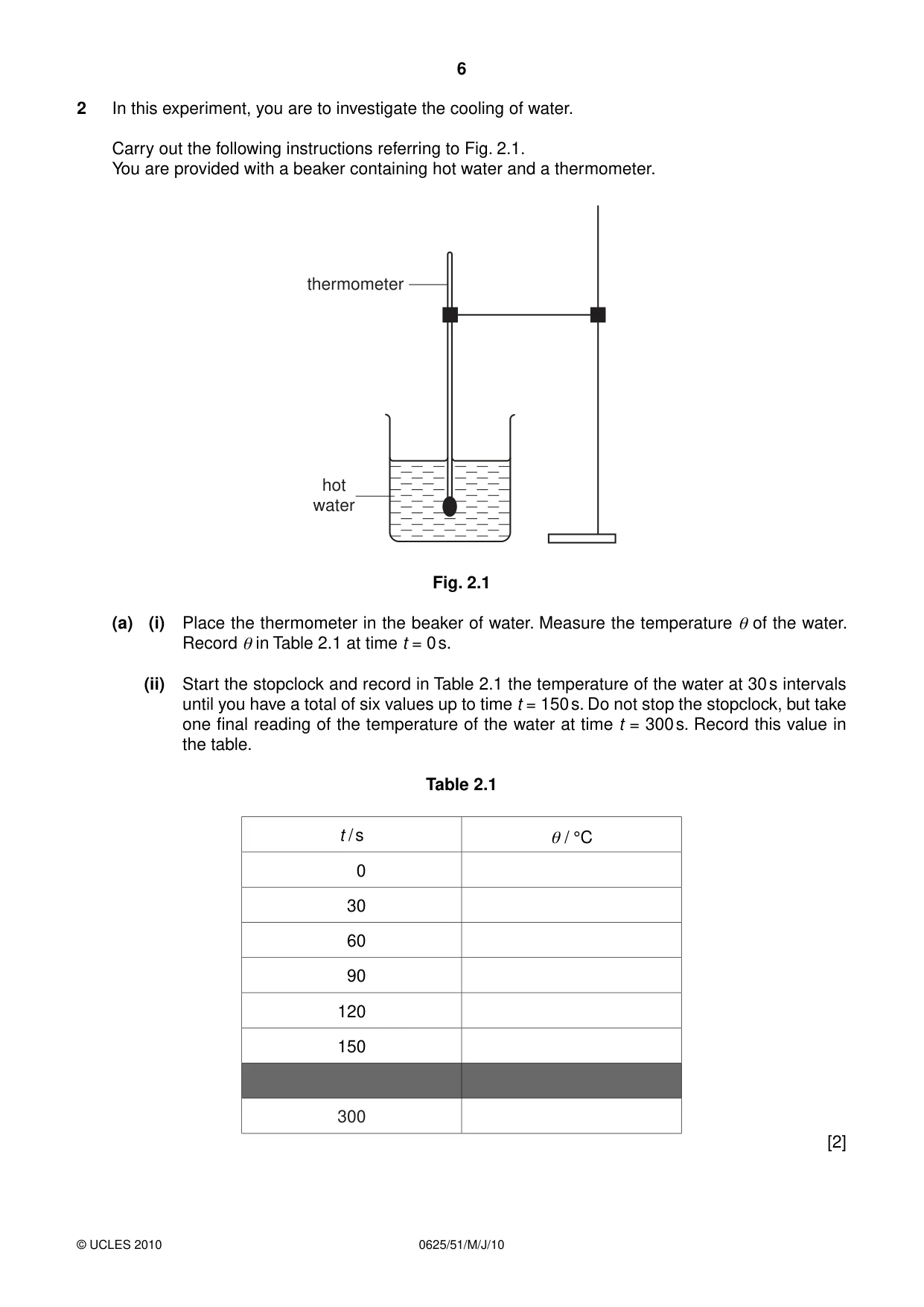
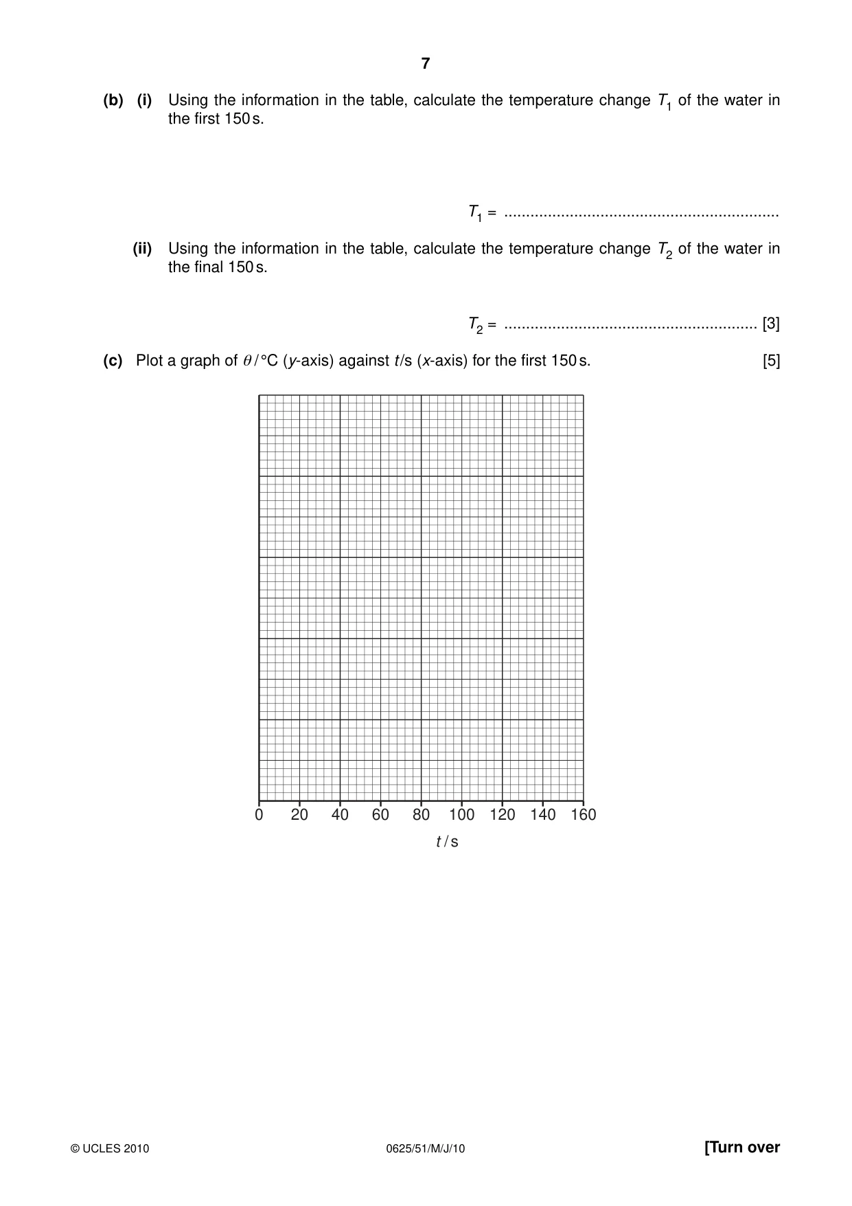
2 In this experiment, you are to investigate the cooling of water. Carry out the following instructions referring to Fig. 2.1. You are provided with a beaker containing hot water and a thermometer. thermometer hot water Fig. 2.1 (a) (i) Place the thermometer in the beaker of water. Measure the temperature θ of the water. Record θ in Table 2.1 at time t = 0 s. (ii) Start the stopclock and record in Table 2.1 the temperature of the water at 30 s intervals until you have a total of six values up to time t = 150 s. Do not stop the stopclock, but take one final reading of the temperature of the water at time t = 300 s. Record this value in the table. Table 2.1 t / s θ / °C 0 30 60 90 120 150 300 [2] (b) (i) Using the information in the table, calculate the temperature change T1 of the water in the first 150 s. T1 = ............................................................... (ii) Using the information in the table, calculate the temperature change T2 of the water in the final 150 s. T2 = .......................................................... [3] (c) Plot a graph of θ / °C (y-axis) against t /s (x-axis) for the first 150 s. [5] 0 20 40 60 80 100 120 140 160 t / s
Mark scheme: 2 (a) temperatures decreasing [1] evidence of temperatures to 1°C [1] (b) T1 correct [1] T2 correct [1] unit °C [1] (c) graph: y-axis labelled [1] plots occupying at least half of grid [1] all plots correct to ½ square [1] well judged line [1] thin line [1] [Total: 10] IGCSE – May/June 2010 0625 51
Q3 · In this experiment, you will investigate the effect of the length of resistance wire in a…
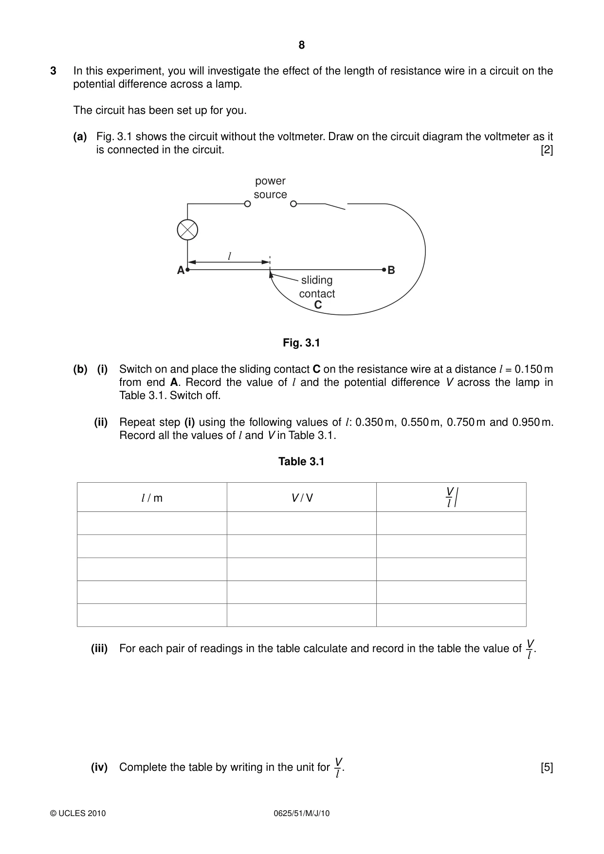
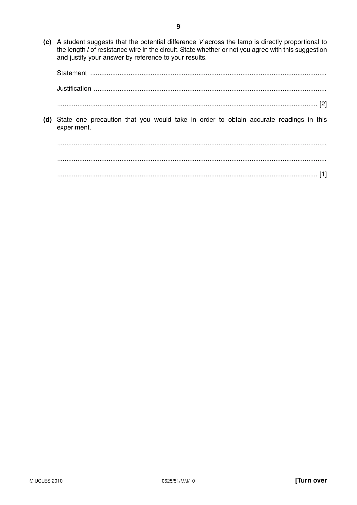
3 In this experiment, you will investigate the effect of the length of resistance wire in a circuit on the potential difference across a lamp. The circuit has been set up for you. (a) Fig. 3.1 shows the circuit without the voltmeter. Draw on the circuit diagram the voltmeter as it is connected in the circuit. [2] power source l A B sliding contact C Fig. 3.1 (b) (i) Switch on and place the sliding contact C on the resistance wire at a distance l = 0.150 m from end A. Record the value of l and the potential difference V across the lamp in Table 3.1. Switch off. (ii) Repeat step (i) using the following values of l: 0.350 m, 0.550 m, 0.750 m and 0.950 m. Record all the values of l and V in Table 3.1. Table 3.1 l / m V / V V–l / (iii) For each pair of readings in the table calculate and record in the table the value of . V–l (iv) Complete the table by writing in the unit for . [5] V–l (c) A student suggests that the potential difference V across the lamp is directly proportional to the length l of resistance wire in the circuit. State whether or not you agree with this suggestion and justify your answer by reference to your results. Statement ................................................................................................................................. Justification ............................................................................................................................... .............................................................................................................................................. [2] (d) State one precaution that you would take in order to obtain accurate readings in this experiment. ................................................................................................................................................... ................................................................................................................................................... .............................................................................................................................................. [1]
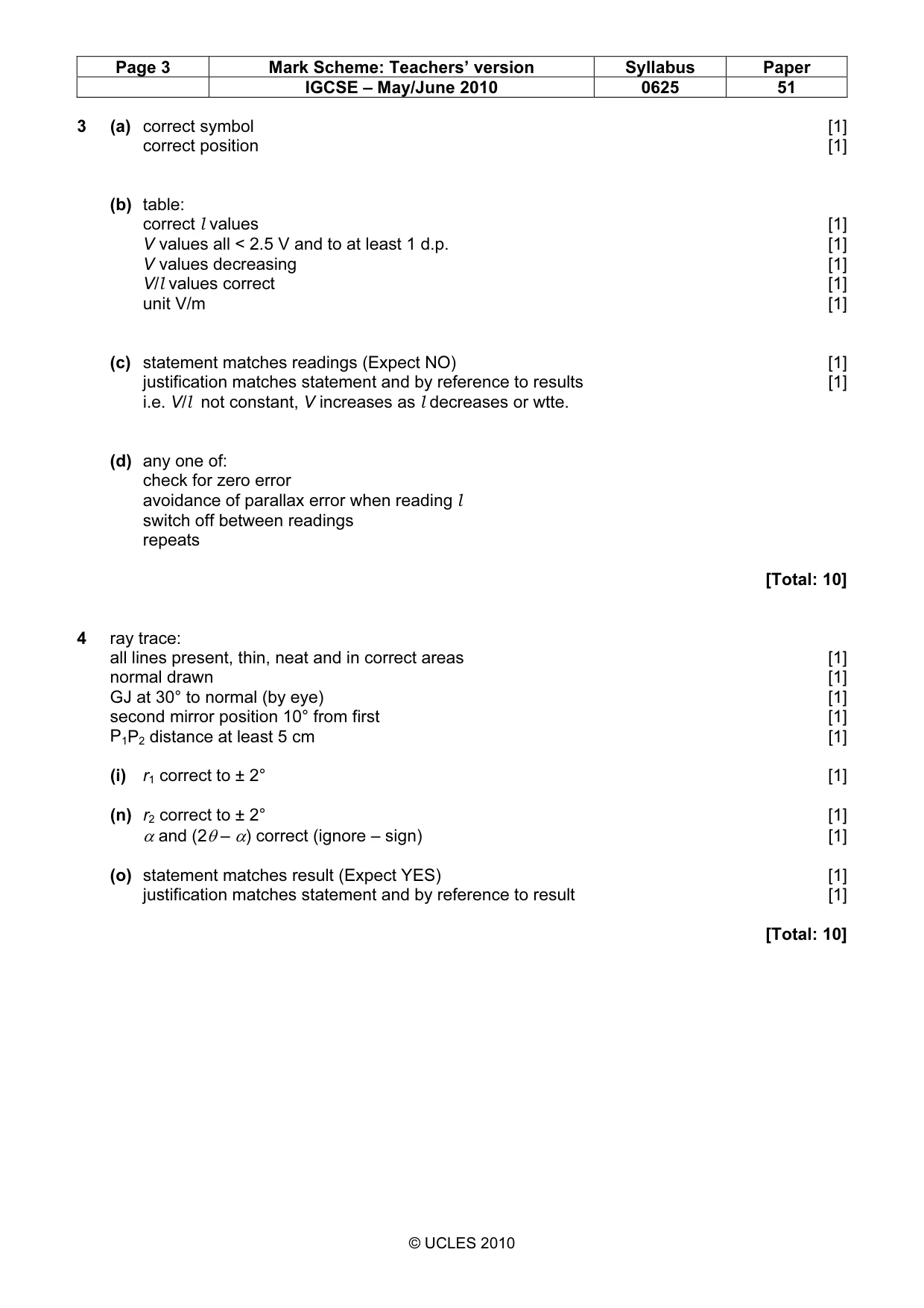
Mark scheme: 3 (a) correct symbol [1] correct position [1] (b) table: correct l values [1] V values all < 2.5 V and to at least 1 d.p. [1] V values decreasing [1] V/l values correct [1] unit V/m [1] (c) statement matches readings (Expect NO) [1] justification matches statement and by reference to results [1] i.e. V/l not constant, V increases as l decreases or wtte. (d) any one of: check for zero error avoidance of parallax error when reading l switch off between readings repeats [Total: 10]
Q4 · In this experiment, you are to investigate reflection from a plane mirror
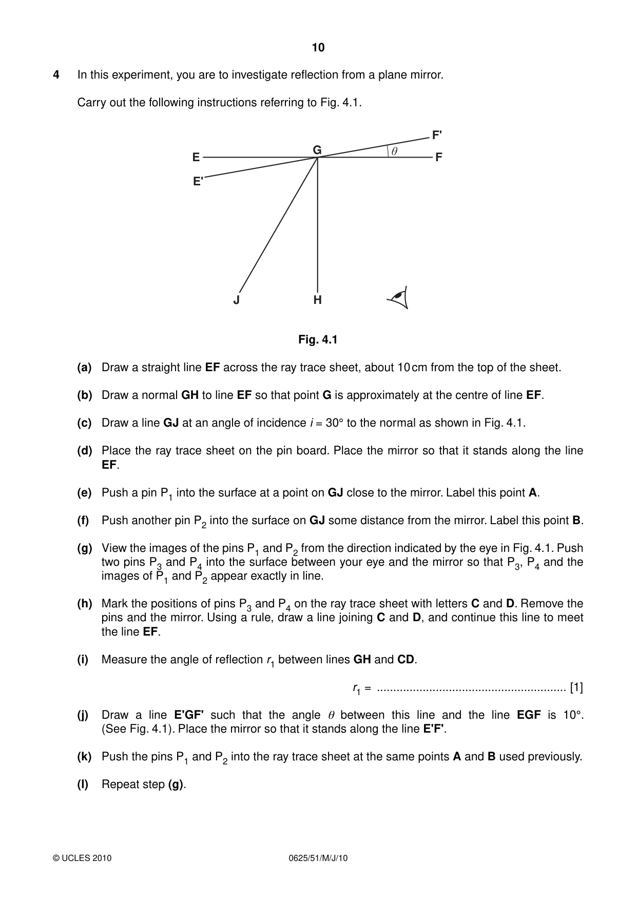
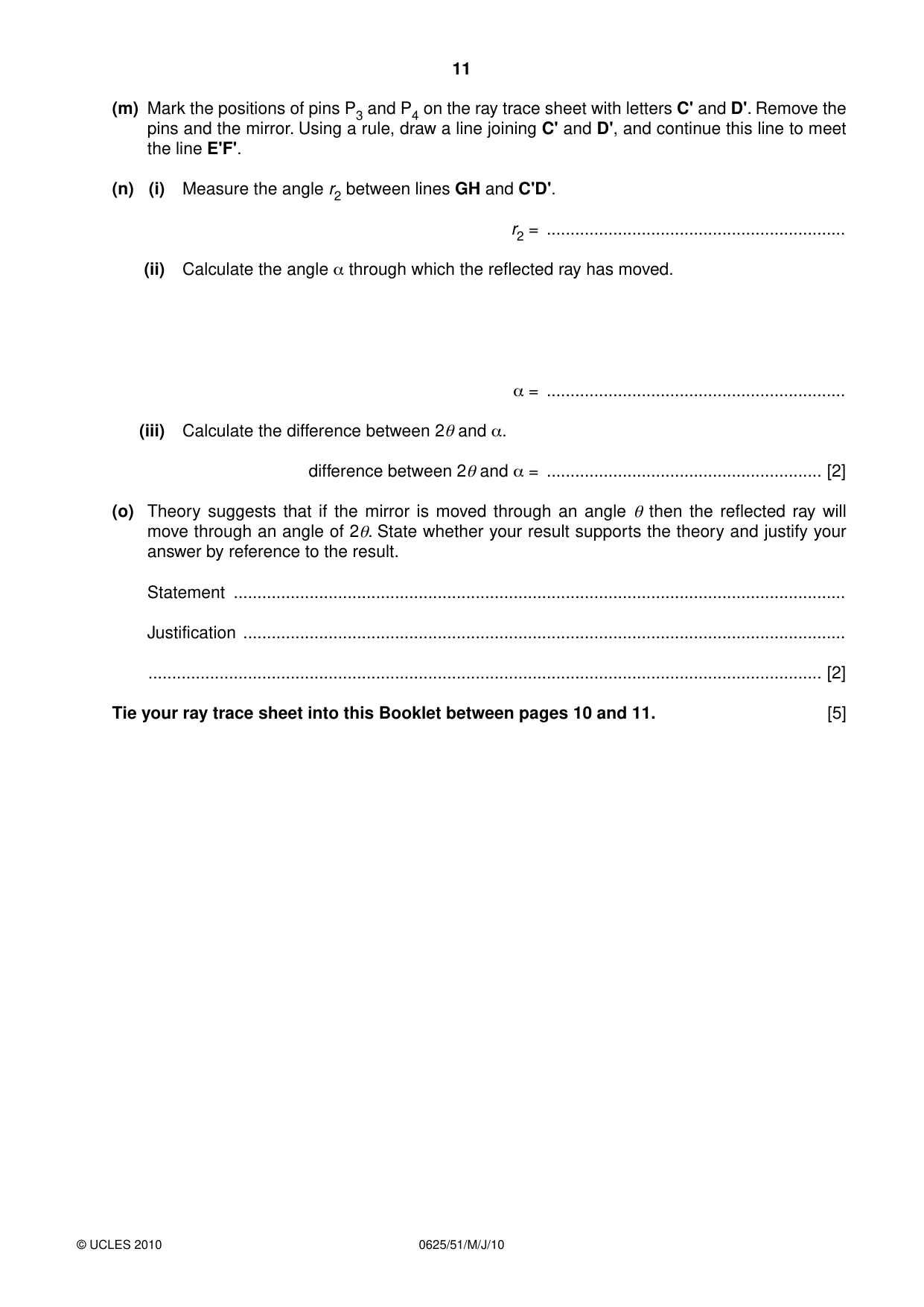
4 In this experiment, you are to investigate reflection from a plane mirror. Carry out the following instructions referring to Fig. 4.1. F' G θ E F E' J H Fig. 4.1 (a) Draw a straight line EF across the ray trace sheet, about 10 cm from the top of the sheet. (b) Draw a normal GH to line EF so that point G is approximately at the centre of line EF. (c) Draw a line GJ at an angle of incidence i = 30° to the normal as shown in Fig. 4.1. (d) Place the ray trace sheet on the pin board. Place the mirror so that it stands along the line EF. (e) Push a pin P1 into the surface at a point on GJ close to the mirror. Label this point A. (f) Push another pin P2 into the surface on GJ some distance from the mirror. Label this point B. (g) View the images of the pins P1 and P2 from the direction indicated by the eye in Fig. 4.1. Push two pins P3 and P4 into the surface between your eye and the mirror so that P3, P4 and the images of P1 and P2 appear exactly in line. (h) Mark the positions of pins P3 and P4 on the ray trace sheet with letters C and D. Remove the pins and the mirror. Using a rule, draw a line joining C and D, and continue this line to meet the line EF. (i) Measure the angle of reflection r1 between lines GH and CD. r1 = .......................................................... [1] (j) Draw a line E'GF' such that the angle θ between this line and the line EGF is 10°. (See Fig. 4.1). Place the mirror so that it stands along the line E'F'. (k) Push the pins P1 and P2 into the ray trace sheet at the same points A and B used previously. (l) Repeat step (g). (m) Mark the positions of pins P3 and P4 on the ray trace sheet with letters C' and D'. Remove the pins and the mirror. Using a rule, draw a line joining C' and D', and continue this line to meet the line E'F'. (n) (i) Measure the angle r2 between lines GH and C'D'. r2 = ............................................................... (ii) Calculate the angle α through which the reflected ray has moved. α = ............................................................... (iii) Calculate the difference between 2θ and α. difference between 2θ and α = .......................................................... [2] (o) Theory suggests that if the mirror is moved through an angle θ then the reflected ray will move through an angle of 2θ. State whether your result supports the theory and justify your answer by reference to the result. Statement ................................................................................................................................. Justification ............................................................................................................................... .............................................................................................................................................. [2] Tie your ray trace sheet into this Booklet between pages 10 and 11. [5]
Mark scheme: 4 ray trace: all lines present, thin, neat and in correct areas [1] normal drawn [1] GJ at 30° to normal (by eye) [1] second mirror position 10° from first [1] P1P2 distance at least 5 cm [1] (i) r1 correct to ± 2° [1] (n) r2 correct to ± 2° [1] α and (2θ – α) correct (ignore – sign) [1] (o) statement matches result (Expect YES) [1] justification matches statement and by reference to result [1] [Total: 10]
What was in this paper
The subtopics covered by these 4 questions, and how many questions each got. Open one in a new tab to see every Cambridge question on it.
What you needed in this session
Cambridge’s own grade thresholds for 2010 May/June, Paper 5 · Variant 1. A higher threshold means an easier paper — the bar moves with how the cohort did.