Cambridge IGCSE Physics 0625 — 2006 May/June Paper 6 · Variant 1
0625/61/M/J/06 · 5 questions · 40 marks · ≈45 min
The question paper and its mark scheme, free to read here and free to download. This is Cambridge’s own paper, exactly as it was sat.
Question paper12 pages
Mark scheme3 pages
Answers below. Sit the paper first if you are practising.
Questions as text
Q1 · The IGCSE class is determining the density of a sample of card
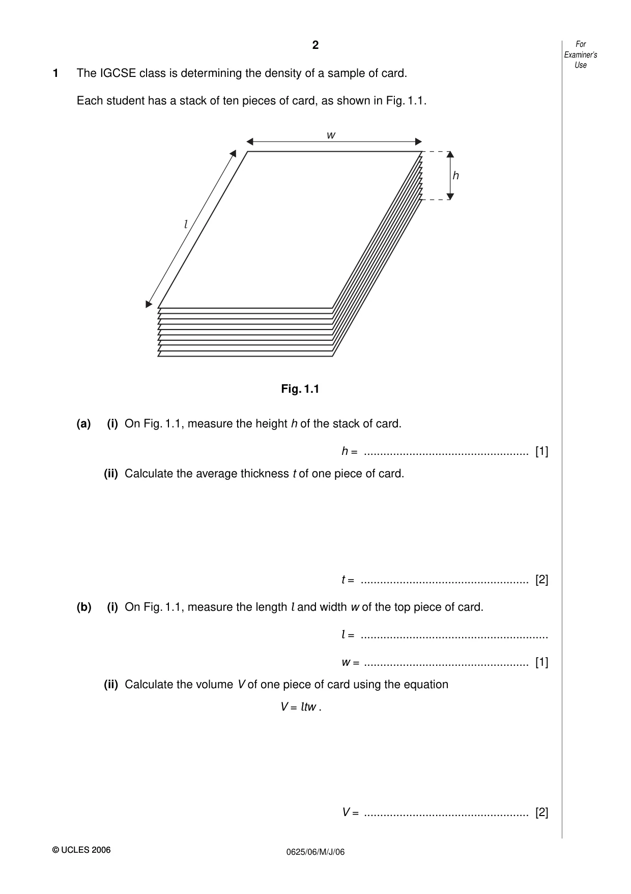
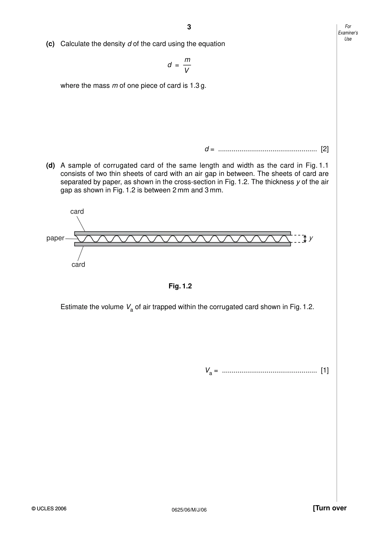
1 The IGCSE class is determining the density of a sample of card. Each student has a stack of ten pieces of card, as shown in Fig. 1.1. w h l Fig. 1.1 (a) (i) On Fig. 1.1, measure the height h of the stack of card. h = ................................................... [1] (ii) Calculate the average thickness t of one piece of card. t = .................................................... [2] (b) (i) On Fig. 1.1, measure the length l and width w of the top piece of card. l = .......................................................... w = ................................................... [1] (ii) Calculate the volume V of one piece of card using the equation V = ltw . V = ................................................... [2] Examiner’s Use (c) Calculate the density d of the card using the equation m d = –– V where the mass m of one piece of card is 1.3 g. d = ................................................... [2] (d) A sample of corrugated card of the same length and width as the card in Fig. 1.1 consists of two thin sheets of card with an air gap in between. The sheets of card are separated by paper, as shown in the cross-section in Fig. 1.2. The thickness y of the air gap as shown in Fig. 1.2 is between 2 mm and 3 mm. card paper y card Fig. 1.2 Estimate the volume Va of air trapped within the corrugated card shown in Fig. 1.2. Va = ................................................. [1]
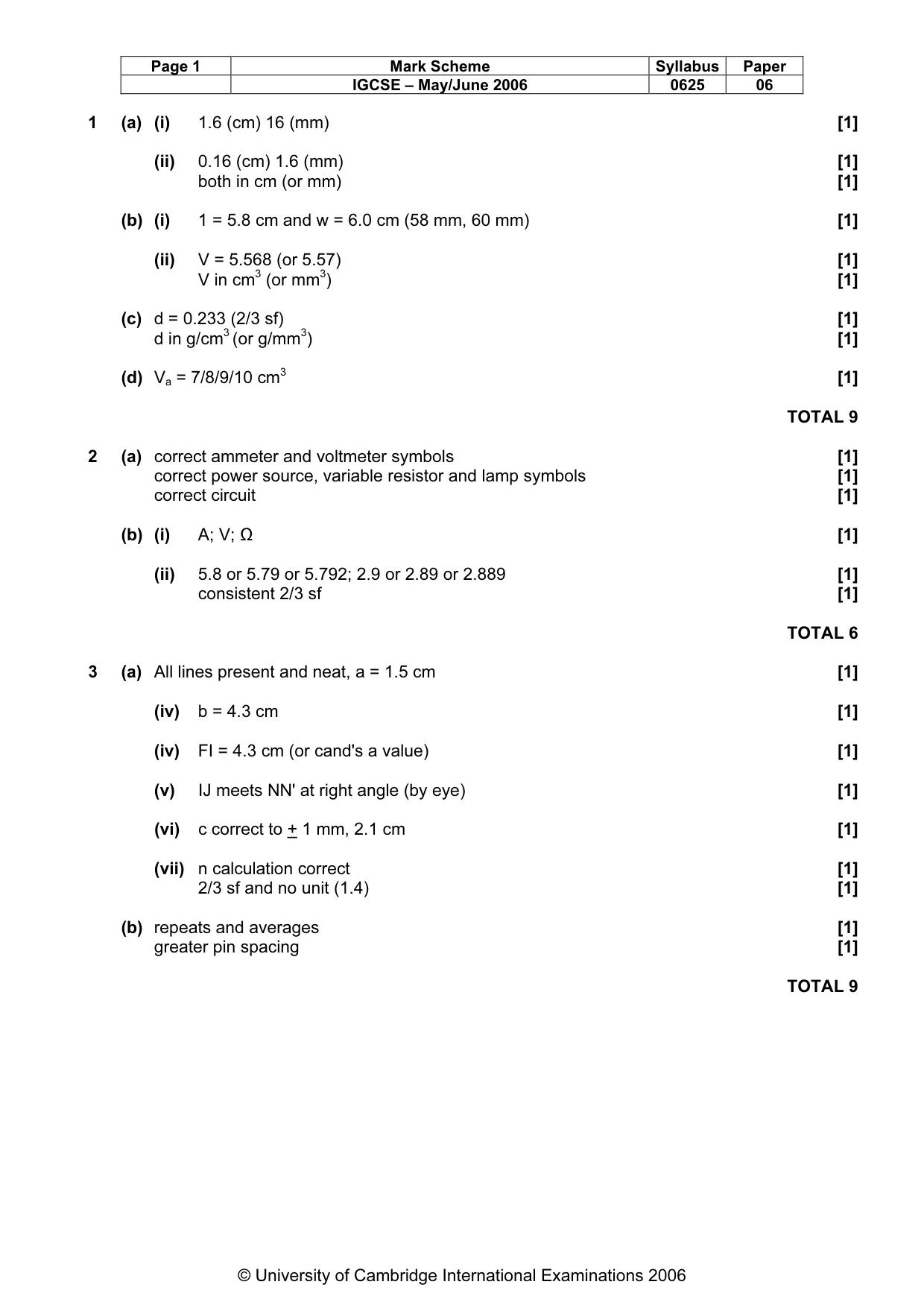
Mark scheme: 1 (a) (i) 1.6 (cm) 16 (mm) [1] (ii) 0.16 (cm) 1.6 (mm) [1] both in cm (or mm) [1] (b) (i) 1 = 5.8 cm and w = 6.0 cm (58 mm, 60 mm) [1] (ii) V = 5.568 (or 5.57) [1] V in cm3 (or mm3) [1] (c) d = 0.233 (2/3 sf) [1] d in g/cm3 (or g/mm3) [1] (d) Va = 7/8/9/10 cm3 [1] TOTAL 9
More questions on Physical quantities and measurement techniques
Q2 · The IGCSE class is investigating the resistance of lamps in different circuit arrangements
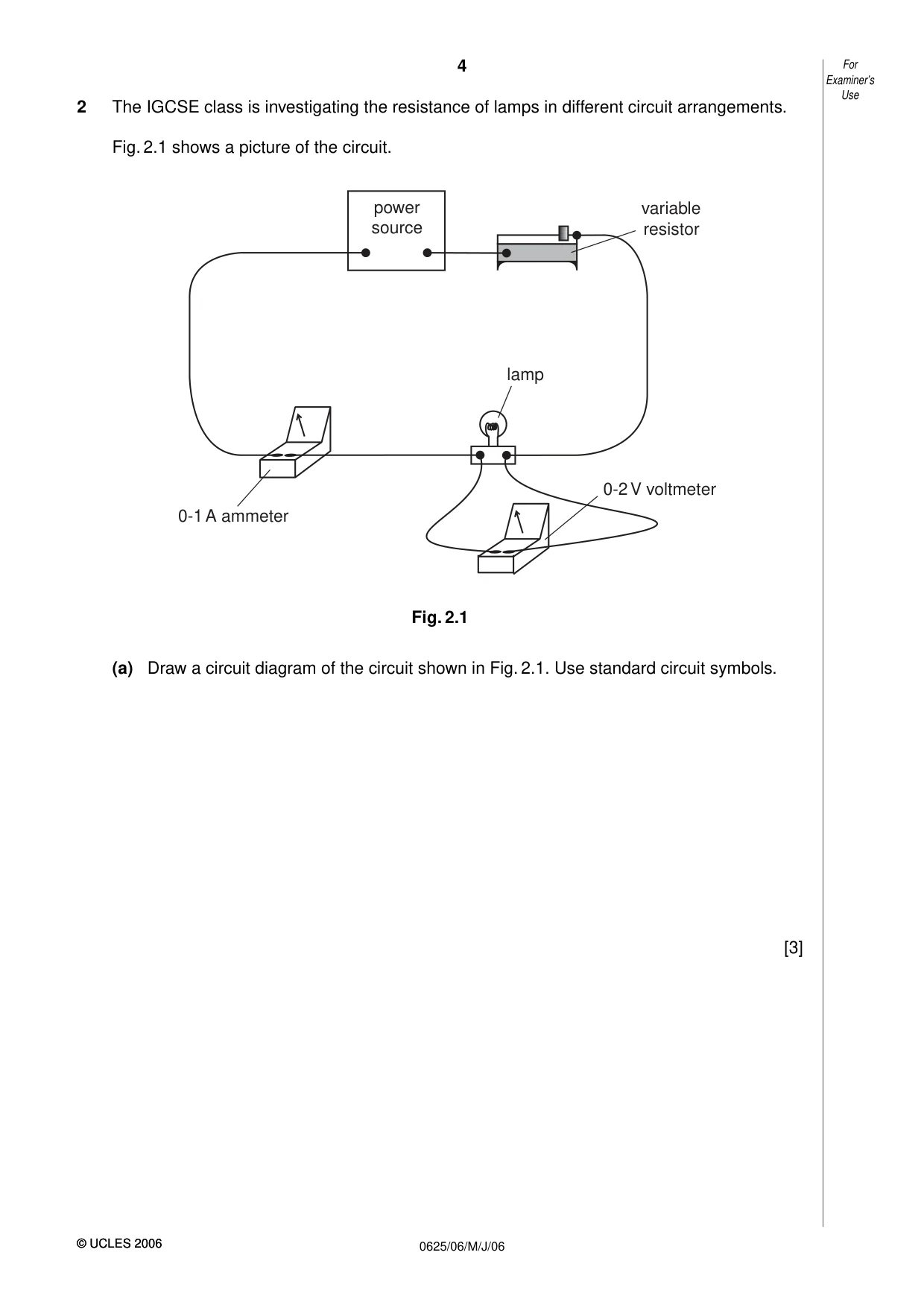
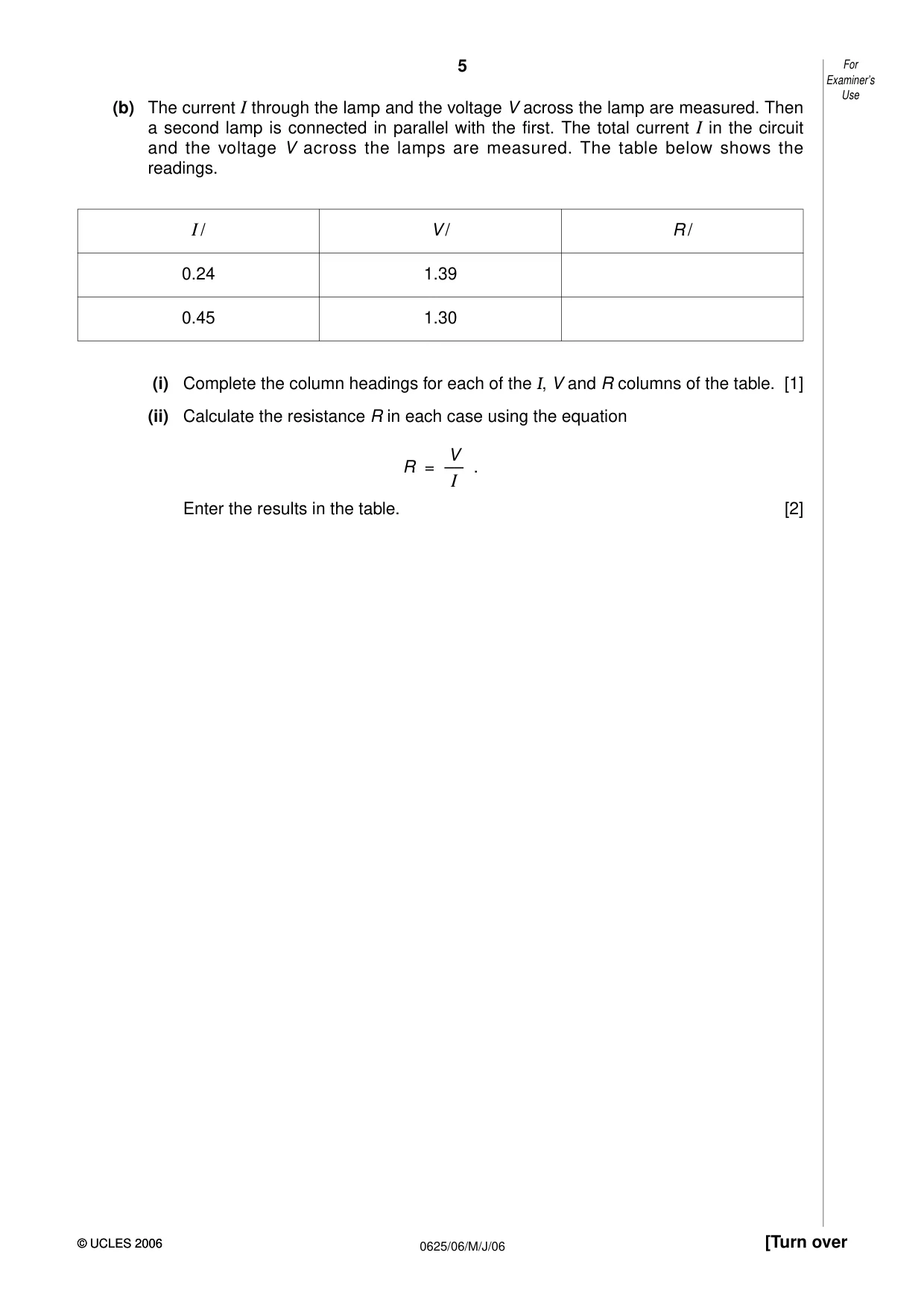
2 The IGCSE class is investigating the resistance of lamps in different circuit arrangements. Fig. 2.1 shows a picture of the circuit. power variable source resistor lamp 0-2 V voltmeter 0-1 A ammeter Fig. 2.1 (a) Draw a circuit diagram of the circuit shown in Fig. 2.1. Use standard circuit symbols. [3] Examiner’s Use (b) The current I through the lamp and the voltage V across the lamp are measured. Then a second lamp is connected in parallel with the first. The total current I in the circuit and the voltage V across the lamps are measured. The table below shows the readings. I / V / R / 0.24 1.39 0.45 1.30 (i) Complete the column headings for each of the I, V and R columns of the table. [1] (ii) Calculate the resistance R in each case using the equation V R = ––I . Enter the results in the table. [2]
Mark scheme: 2 (a) correct ammeter and voltmeter symbols [1] correct power source, variable resistor and lamp symbols [1] correct circuit [1] (b) (i) A; V; Ω [1] (ii) 5.8 or 5.79 or 5.792; 2.9 or 2.89 or 2.889 [1] consistent 2/3 sf [1] TOTAL 6
Q3 · The IGCSE class is determining the refractive index of the material of a transparent block
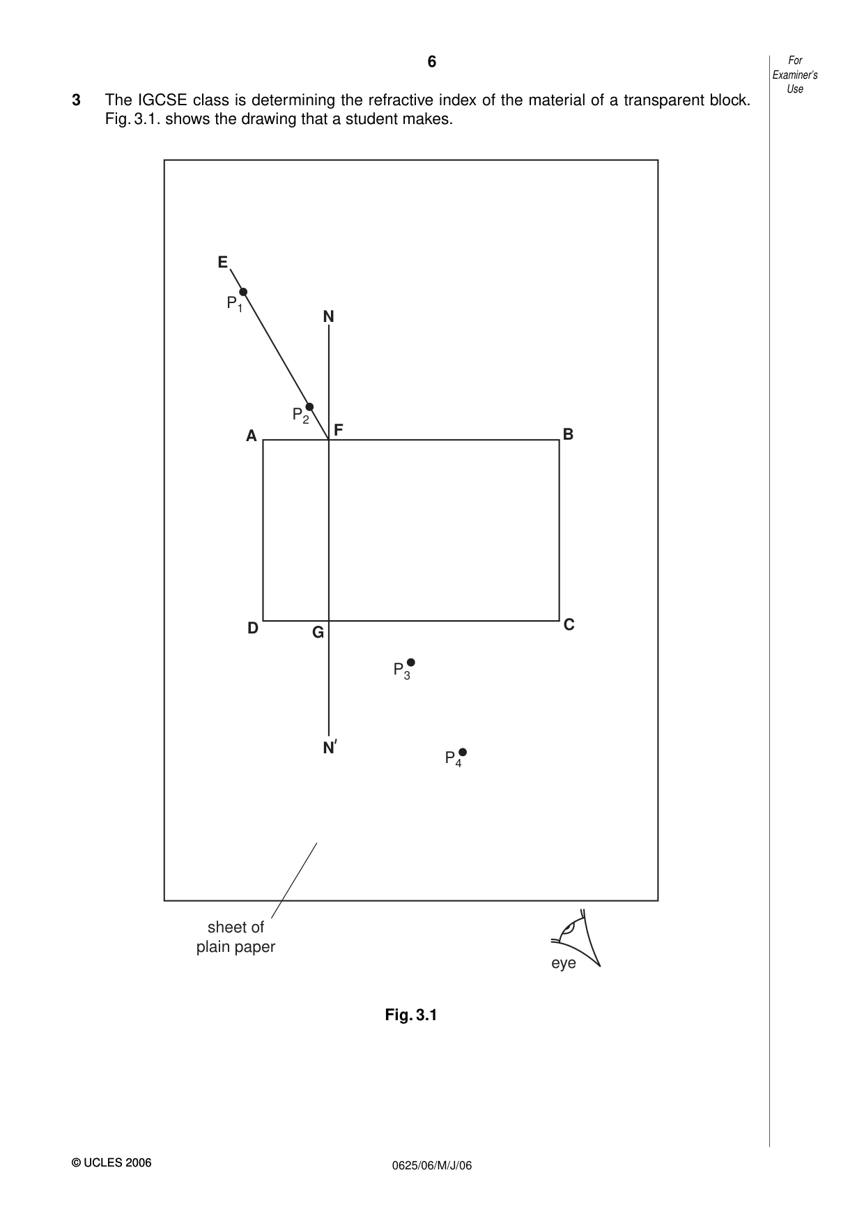
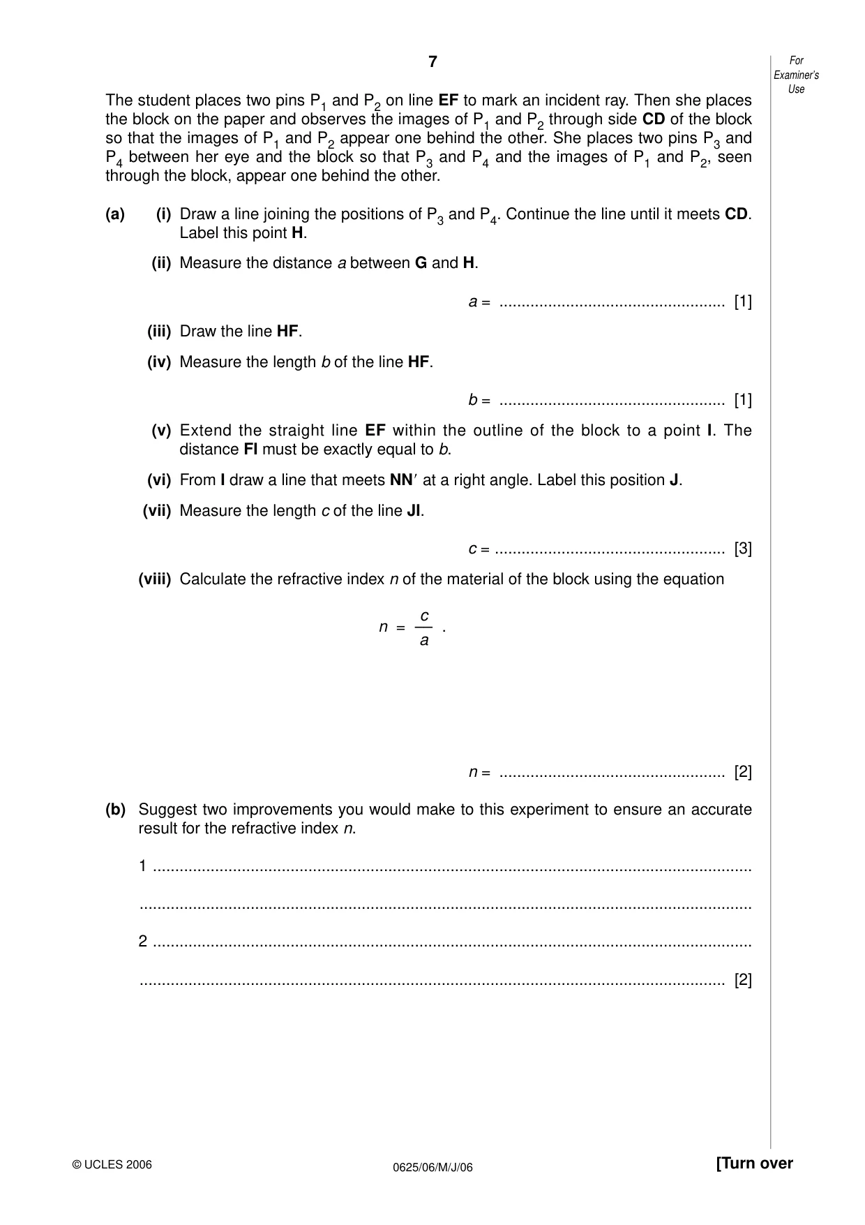
3 The IGCSE class is determining the refractive index of the material of a transparent block. Fig. 3.1. shows the drawing that a student makes. E P1 N P2 F B A D G C P3 N P4 sheet of plain paper eye Fig. 3.1 Examiner’s Use The student places two pins P1 and P2 on line EF to mark an incident ray. Then she places the block on the paper and observes the images of P1 and P2 through side CD of the block so that the images of P1 and P2 appear one behind the other. She places two pins P3 and P4 between her eye and the block so that P3 and P4 and the images of P1 and P2, seen through the block, appear one behind the other. (a) (i) Draw a line joining the positions of P3 and P4. Continue the line until it meets CD. Label this point H. (ii) Measure the distance a between G and H. a = ................................................... [1] (iii) Draw the line HF. (iv) Measure the length b of the line HF. b = ................................................... [1] (v) Extend the straight line EF within the outline of the block to a point I. The distance FI must be exactly equal to b. (vi) From I draw a line that meets NN at a right angle. Label this position J. (vii) Measure the length c of the line JI. c = .................................................... [3] (viii) Calculate the refractive index n of the material of the block using the equation c n = –– . a n = ................................................... [2] (b) Suggest two improvements you would make to this experiment to ensure an accurate result for the refractive index n. 1 ....................................................................................................................................... .......................................................................................................................................... 2 ....................................................................................................................................... .................................................................................................................................... [2]
Mark scheme: 3 (a) All lines present and neat, a = 1.5 cm [1] (iv) b = 4.3 cm [1] (iv) FI = 4.3 cm (or cand's a value) [1] (v) IJ meets NN' at right angle (by eye) [1] (vi) c correct to + 1 mm, 2.1 cm [1] (vii) n calculation correct [1] 2/3 sf and no unit (1.4) [1] (b) repeats and averages [1] greater pin spacing [1] TOTAL 9 IGCSE – May/June 2006 0625 06
Q4 · An IGCSE student is investigating the temperature rise of water in beakers heated by…
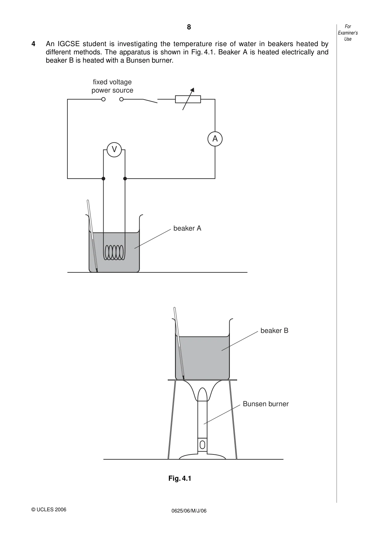
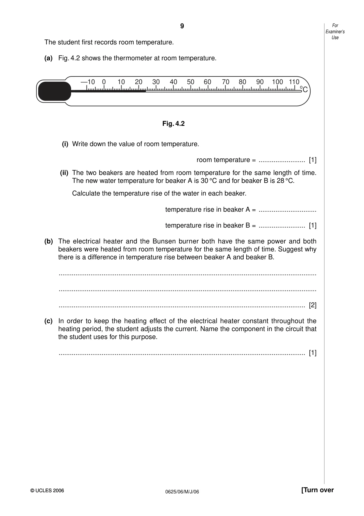
4 An IGCSE student is investigating the temperature rise of water in beakers heated by different methods. The apparatus is shown in Fig. 4.1. Beaker A is heated electrically and beaker B is heated with a Bunsen burner. fixed voltage power source A V beaker A beaker B Bunsen burner Fig. 4.1 Examiner’s Use The student first records room temperature. (a) Fig. 4.2 shows the thermometer at room temperature. —10 0 10 20 30 40 50 60 70 80 90 100 110 oC Fig. 4.2 (i) Write down the value of room temperature. room temperature = ......................... [1] (ii) The two beakers are heated from room temperature for the same length of time. The new water temperature for beaker A is 30 °C and for beaker B is 28 °C. Calculate the temperature rise of the water in each beaker. temperature rise in beaker A = ............................... temperature rise in beaker B = ......................... [1] (b) The electrical heater and the Bunsen burner both have the same power and both beakers were heated from room temperature for the same length of time. Suggest why there is a difference in temperature rise between beaker A and beaker B. .......................................................................................................................................... .......................................................................................................................................... .................................................................................................................................... [2] (c) In order to keep the heating effect of the electrical heater constant throughout the heating period, the student adjusts the current. Name the component in the circuit that the student uses for this purpose. .................................................................................................................................... [1]
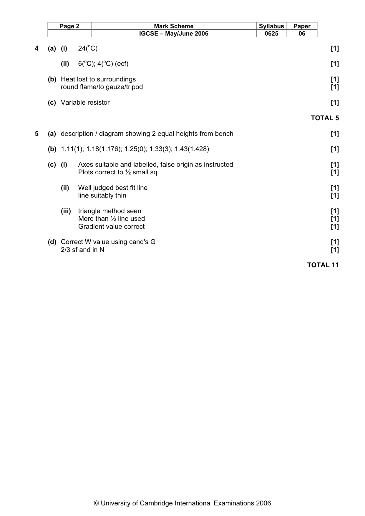
Mark scheme: 4 (a) (i) 24(oC) [1] (ii) 6(oC); 4(oC) (ecf) [1] (b) Heat lost to surroundings [1] round flame/to gauze/tripod [1] (c) Variable resistor [1] TOTAL 5
Q5 · The IGCSE class is determining the weight of a metre rule
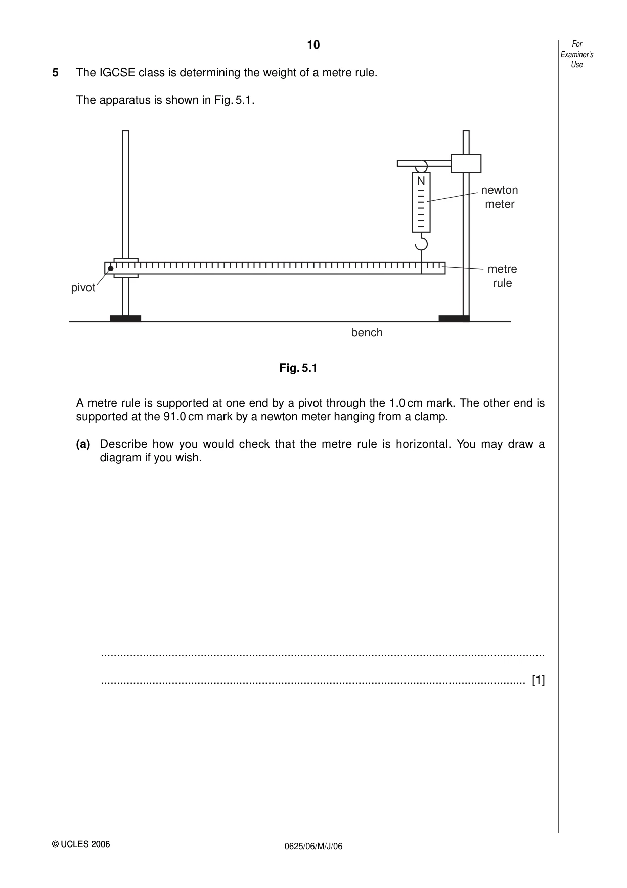
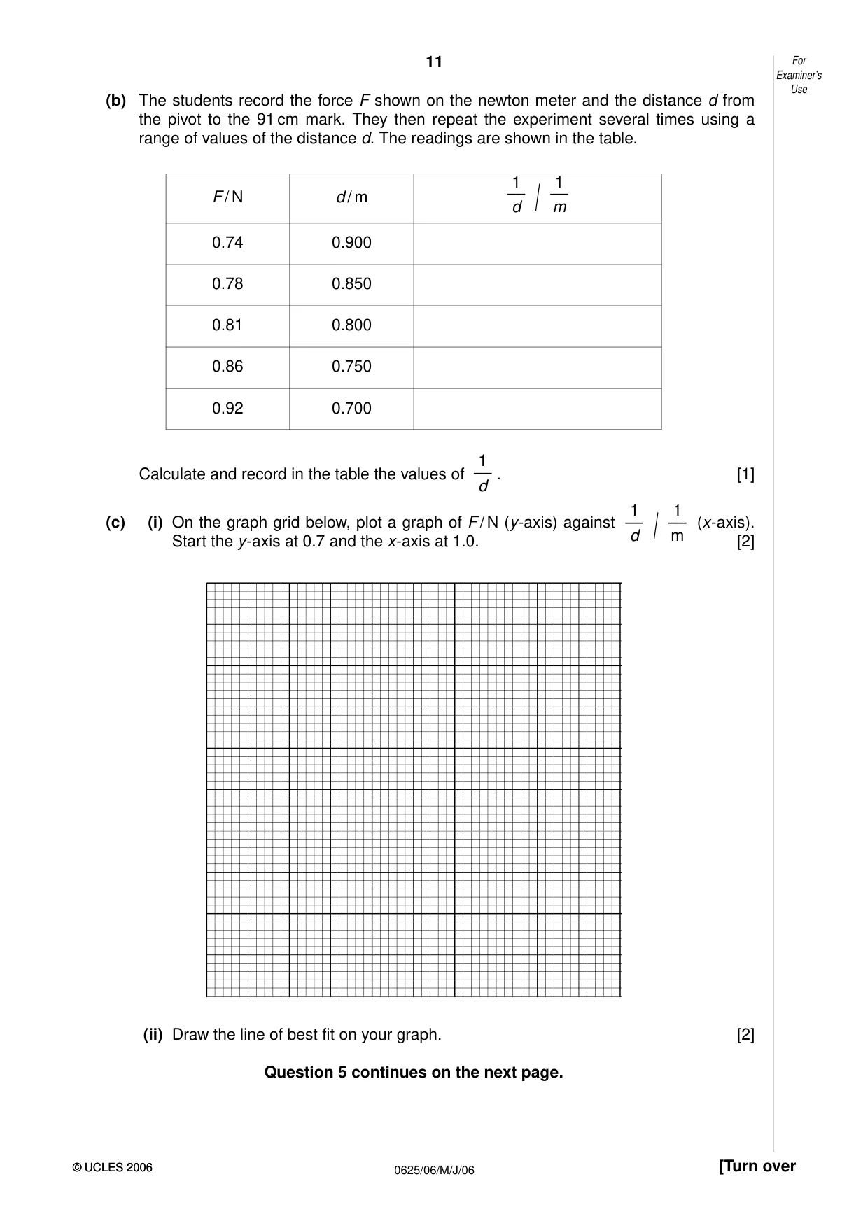
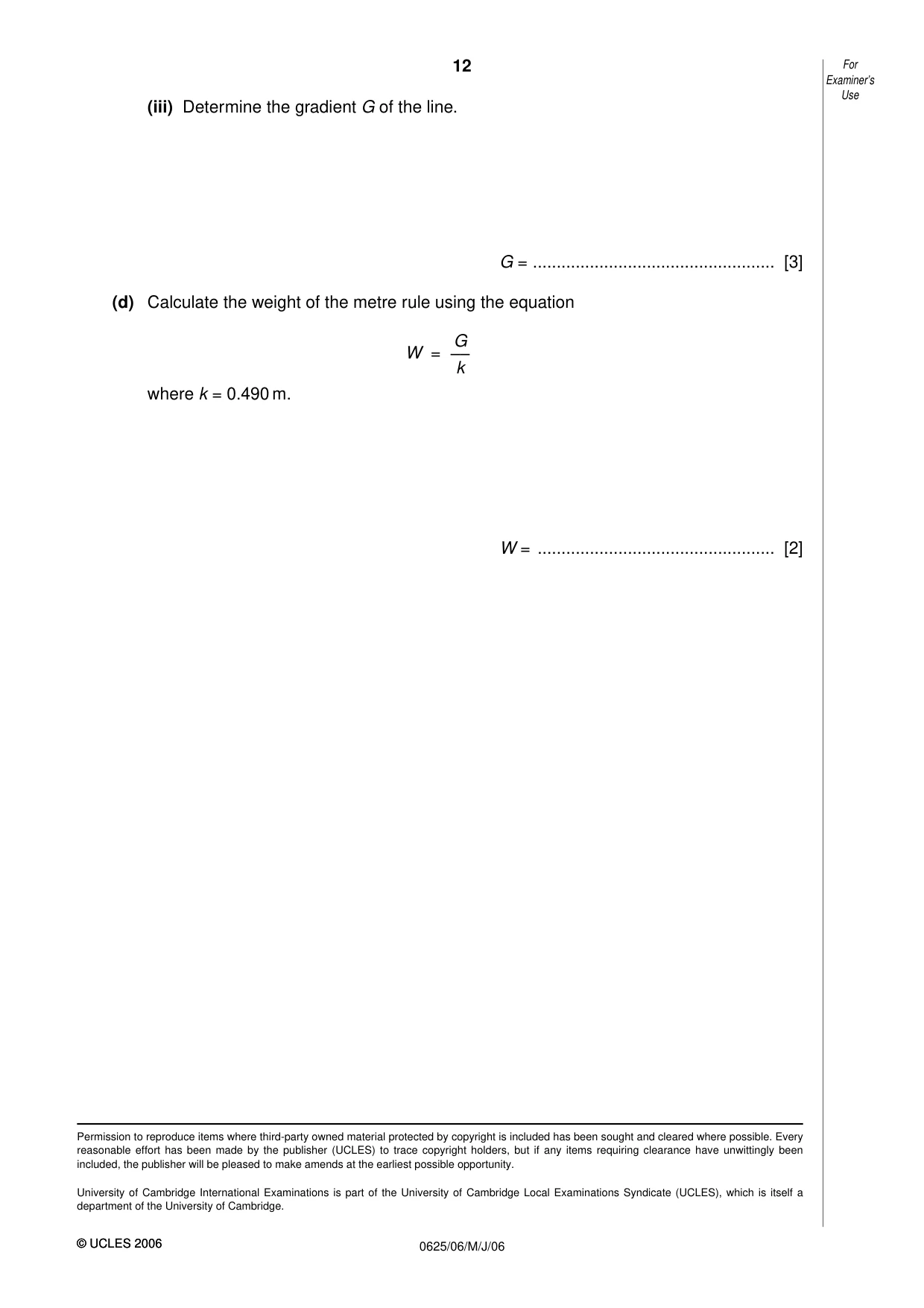
5 The IGCSE class is determining the weight of a metre rule. The apparatus is shown in Fig. 5.1. N newton meter metre rule pivot bench Fig. 5.1 A metre rule is supported at one end by a pivot through the 1.0 cm mark. The other end is supported at the 91.0 cm mark by a newton meter hanging from a clamp. (a) Describe how you would check that the metre rule is horizontal. You may draw a diagram if you wish. .......................................................................................................................................... .................................................................................................................................... [1] Examiner’s Use (b) The students record the force F shown on the newton meter and the distance d from the pivot to the 91 cm mark. They then repeat the experiment several times using a range of values of the distance d. The readings are shown in the table. 1 1 F / N d / m –– –– d / m 0.74 0.900 0.78 0.850 0.81 0.800 0.86 0.750 0.92 0.700 1 Calculate and record in the table the values of –– . [1] d 1 1 (c) (i) On the graph grid below, plot a graph of F / N (y-axis) against –– –– (x-axis). d / m Start the y-axis at 0.7 and the x-axis at 1.0. [2] (ii) Draw the line of best fit on your graph. [2] Question 5 continues on the next page. Examiner’s Use (iii) Determine the gradient G of the line. G = ................................................... [3] (d) Calculate the weight of the metre rule using the equation G W = –– k where k = 0.490 m. W = .................................................. [2]
Mark scheme: 5 (a) description / diagram showing 2 equal heights from bench [1] (b) 1.11(1); 1.18(1.176); 1.25(0); 1.33(3); 1.43(1.428) [1] (c) (i) Axes suitable and labelled, false origin as instructed [1] Plots correct to ½ small sq [1] (ii) Well judged best fit line [1] line suitably thin [1] (iii) triangle method seen [1] More than ½ line used [1] Gradient value correct [1] (d) Correct W value using cand's G [1] 2/3 sf and in N [1] TOTAL 11
What was in this paper
The subtopics covered by these 5 questions, and how many questions each got. Open one in a new tab to see every Cambridge question on it.
What you needed in this session
Cambridge’s own grade thresholds for 2006 May/June, Paper 6 · Variant 1. A higher threshold means an easier paper — the bar moves with how the cohort did.