Cambridge A Level Physics 9702 — 2015 Oct/Nov Paper 4 · Variant 3
9702/43/O/N/15 · 13 questions · 100 marks · ≈113 min
The question paper and its mark scheme, free to read here and free to download. This is Cambridge’s own paper, exactly as it was sat.
Question paper24 pages
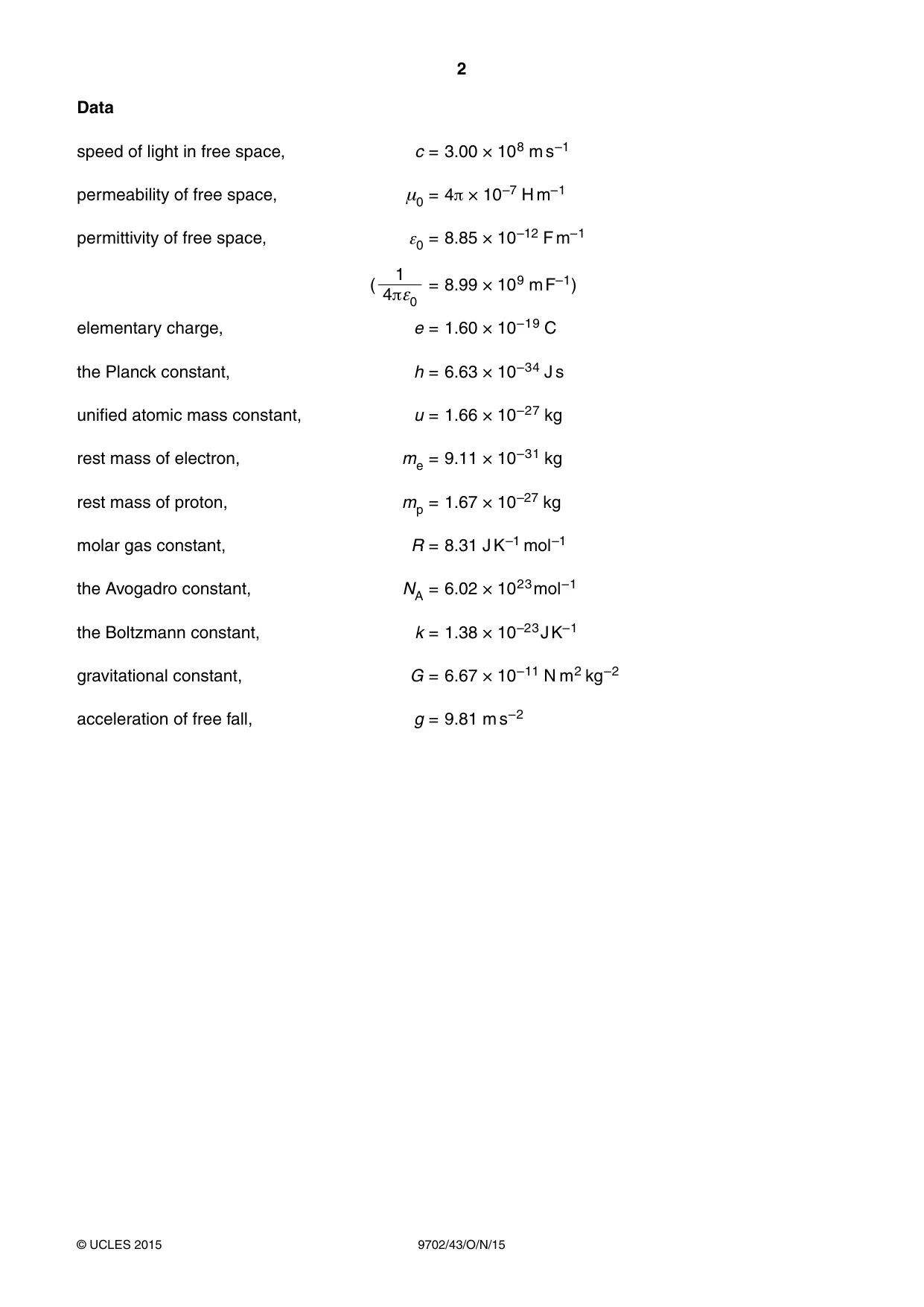
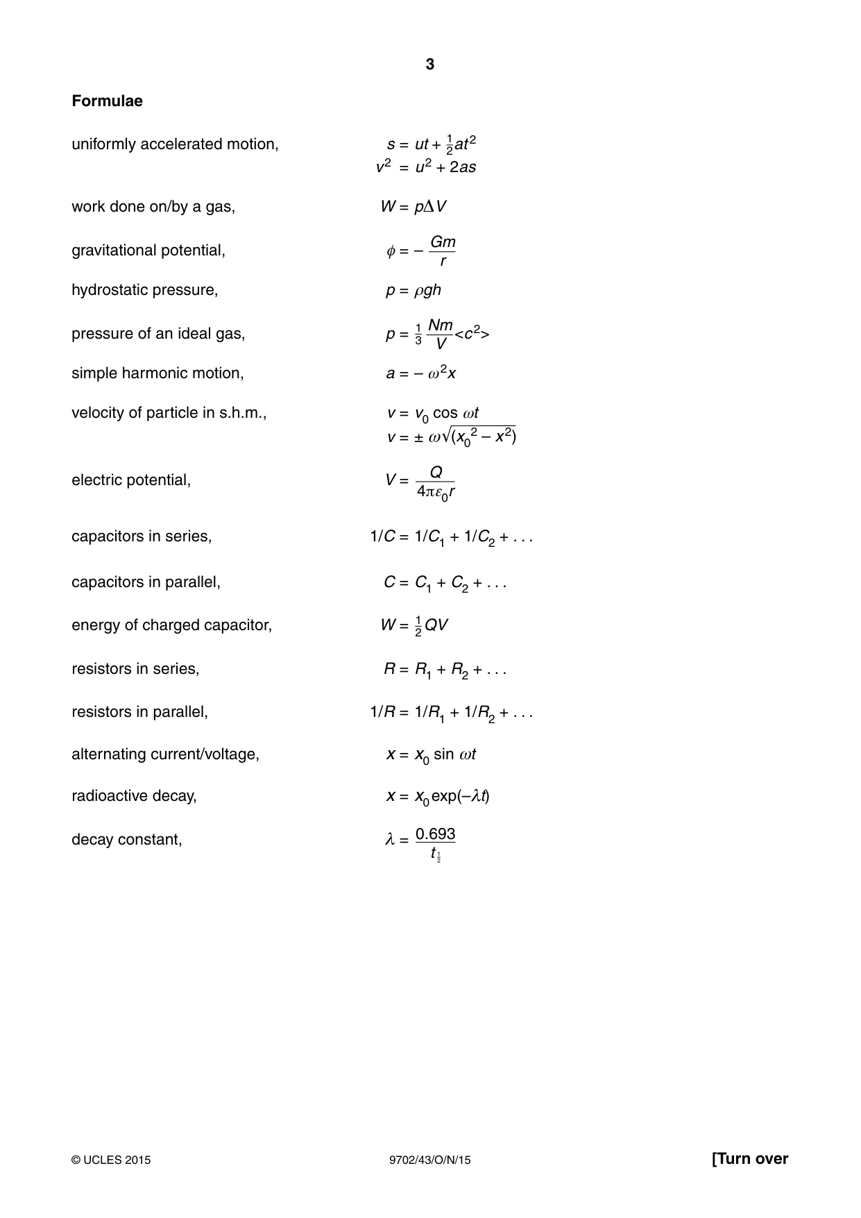
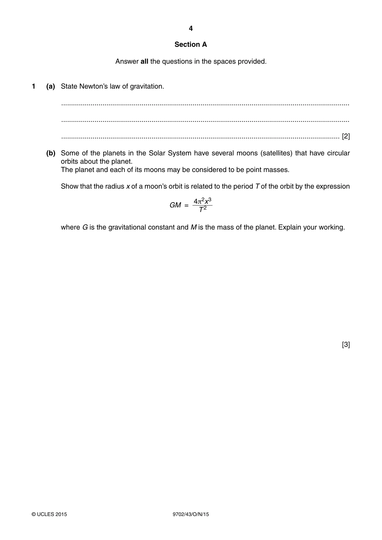


Mark scheme7 pages
Answers below. Sit the paper first if you are practising.
Questions as text
Q1 · State Newton’s law of gravitation
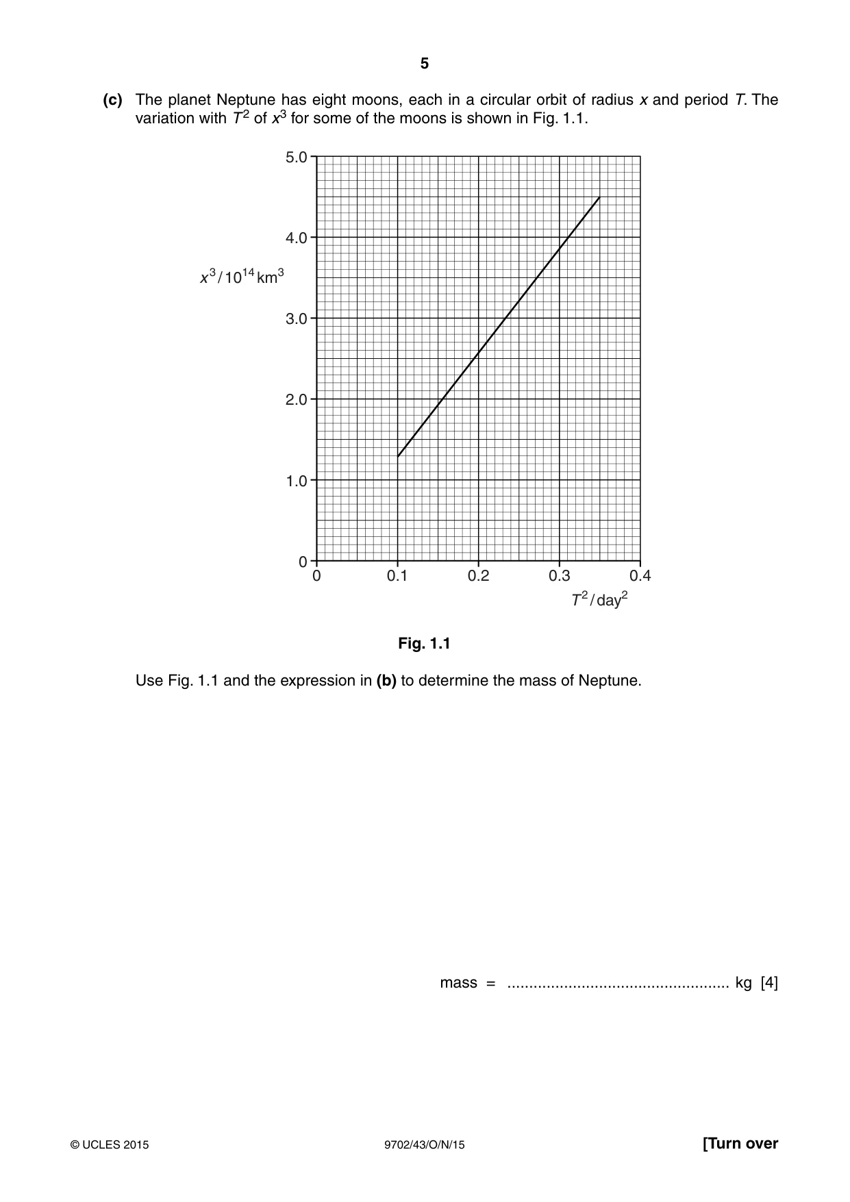
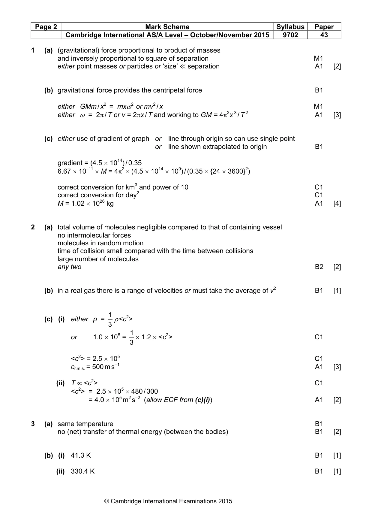
1 (a) State Newton’s law of gravitation. ................................................................................................................................................... ................................................................................................................................................... .............................................................................................................................................. [2] (b) Some of the planets in the Solar System have several moons (satellites) that have circular orbits about the planet. The planet and each of its moons may be considered to be point masses. Show that the radius x of a moon’s orbit is related to the period T of the orbit by the expression 4π2x3 GM = 2 T where G is the gravitational constant and M is the mass of the planet. Explain your working. [3] (c) The planet Neptune has eight moons, each in a circular orbit of radius x and period T. The variation with T 2 of x3 for some of the moons is shown in Fig. 1.1. 5.0 4.0 x 3 / 1014 km3 3.0 2.0 1.0 0 0 0.1 0.2 0.3 0.4 T 2 / day2 Fig. 1.1 Use Fig. 1.1 and the expression in (b) to determine the mass of Neptune. mass = ................................................... kg [4]
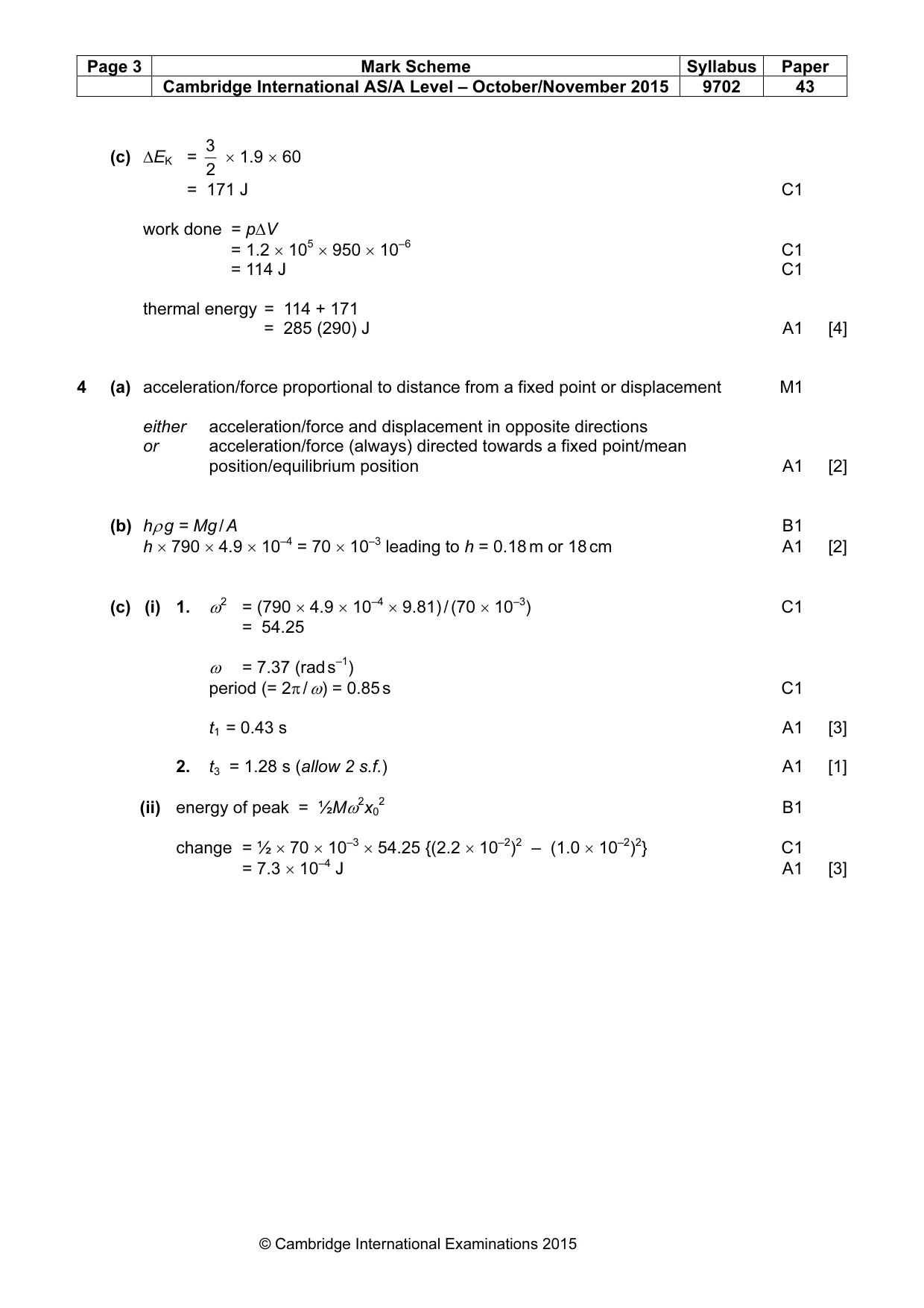
Mark scheme: 1 (a) (gravitational) force proportional to product of masses and inversely proportional to square of separation M1 either point masses or particles or ‘size’ ≪ separation A1 [2] (b) gravitational force provides the centripetal force B1 either GMm / x2 = mxω2 or mv2 / x M1 either ω = 2π / T or v = 2πx / T and working to GM = 4π2x 3 / T 2 A1 [3] (c) either use of gradient of graph or line through origin so can use single point or line shown extrapolated to origin B1 gradient = (4.5 × 10¹⁴) / 0.35 6.67 × 10⁻¹¹ × M = 4π2 × (4.5 × 1014 × 109) / (0.35 × {24 × 3600}2) correct conversion for km3 and power of 10 C1 correct conversion for day2 C1 M = 1.02 × 1026 kg A1 [4]
Q2 · An ideal gas is said to consist of molecules that are hard elastic identical spheres
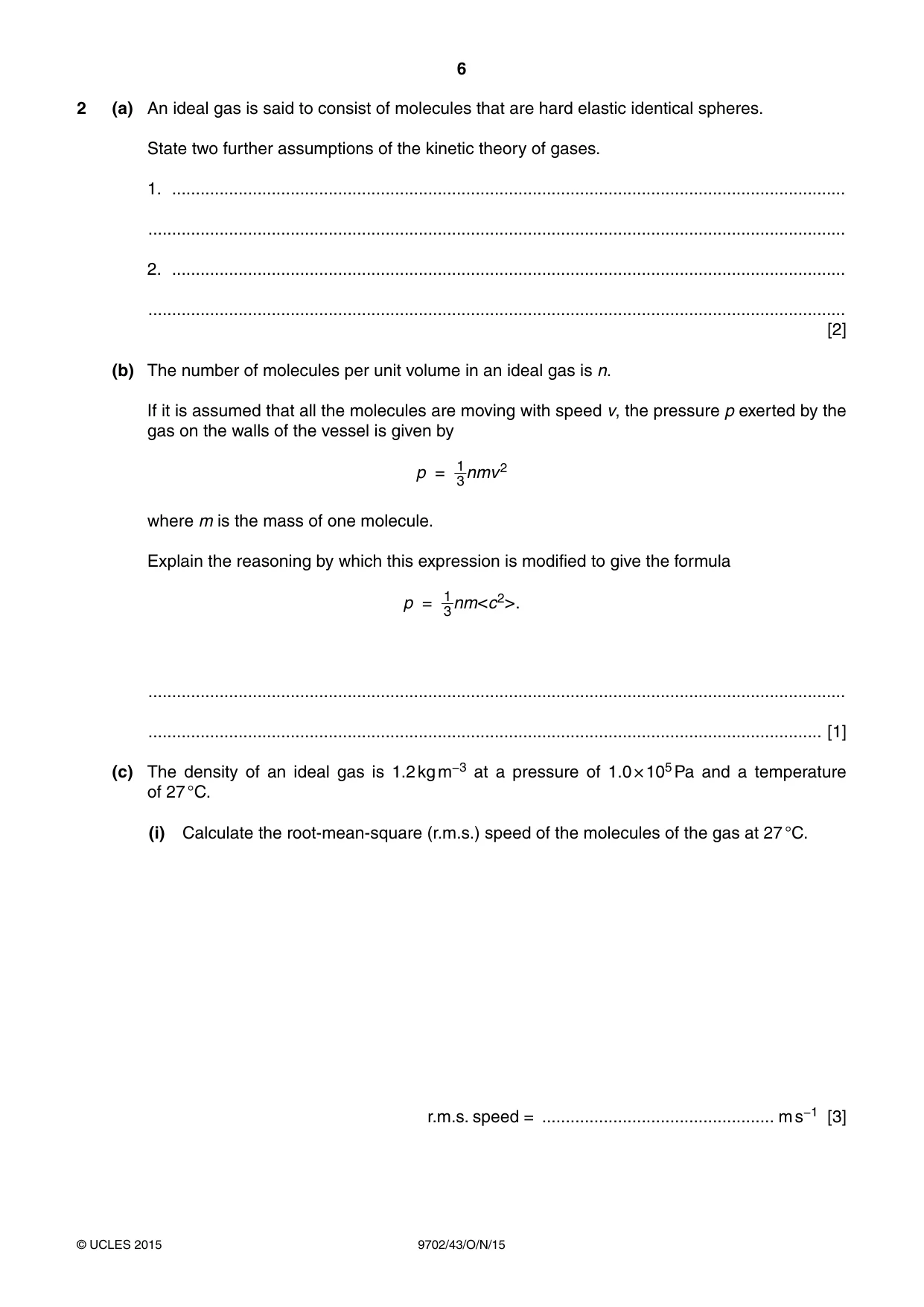
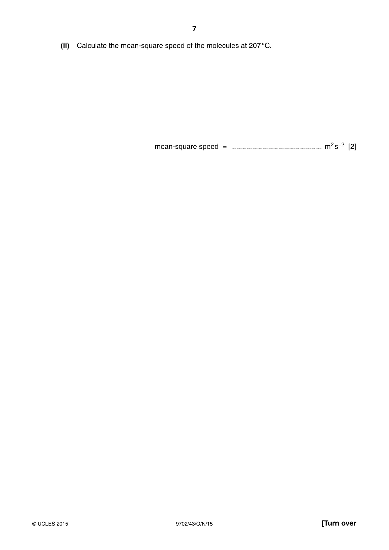
2 (a) An ideal gas is said to consist of molecules that are hard elastic identical spheres. State two further assumptions of the kinetic theory of gases. 1. .............................................................................................................................................. ................................................................................................................................................... 2. .............................................................................................................................................. ................................................................................................................................................... [2] (b) The number of molecules per unit volume in an ideal gas is n. If it is assumed that all the molecules are moving with speed v, the pressure p exerted by the gas on the walls of the vessel is given by 1 p = 3nmv2 where m is the mass of one molecule. Explain the reasoning by which this expression is modified to give the formula 1 p = 3nm<c2>. ................................................................................................................................................... .............................................................................................................................................. [1] (c) The density of an ideal gas is 1.2 kg m−3 at a pressure of 1.0 × 10⁵ Pa and a temperature of 27 °C. (i) Calculate the root-mean-square (r.m.s.) speed of the molecules of the gas at 27 °C. r.m.s. speed = ................................................. m s−1 [3] (ii) Calculate the mean-square speed of the molecules at 207 °C. mean-square speed = ............................................. m2 s−2 [2]
Mark scheme: 2 (a) total volume of molecules negligible compared to that of containing vessel no intermolecular forces molecules in random motion time of collision small compared with the time between collisions large number of molecules any two B2 [2] (b) in a real gas there is a range of velocities or must take the average of v2 B1 [1] 1 (c) (i) either p = ρ <c2> 3 1 or 1.0 × 105 = × 1.2 × <c2> C1 3 <c2> = 2.5 × 10⁵ C1 cr.m.s. = 500 m s–1 A1 [3] (ii) T ∝ <c2> C1 <c2> = 2.5 × 105 × 480 / 300 = 4.0 × 10⁵ m2 s–2 (allow ECF from (c)(i)) A1 [2]
Q3 · Two bodies are in thermal equilibrium
3 (a) Two bodies are in thermal equilibrium. State what is meant by thermal equilibrium. ................................................................................................................................................... ................................................................................................................................................... .............................................................................................................................................. [2] (b) The temperature of a body is found to increase from 15.9 °C to 57.2 °C. Determine, in kelvin and to an appropriate number of decimal places, (i) the rise in temperature of the body, temperature rise = ..................................................... K [1] (ii) the final temperature. temperature = ..................................................... K [1] (c) An ideal gas at a constant pressure of 1.2 × 10⁵ Pa is heated from a temperature of 290 K to a final temperature of 350 K. The change in volume of the gas is 950 cm3. The total change in kinetic energy ΔEK, measured in joules, of the gas molecules is given by the expression 3 ΔEK = 2 × 1.9 × ΔT where ΔT is the change in temperature in kelvin. Determine the thermal energy required to produce the change in temperature from 290 K to 350 K. energy = ...................................................... J [4]
Mark scheme: 3 (a) same temperature B1 no (net) transfer of thermal energy (between the bodies) B1 [2] (b) (i) 41.3 K B1 [1] (ii) 330.4 K B1 [1] 3 (c) ∆EK = × 1.9 × 60 2 = 171 J C1 work done = p∆V = 1.2 × 105 × 950 × 10–6 C1 = 114 J C1 thermal energy = 114 + 171 = 285 (290) J A1 [4]
Q4 · Define simple harmonic motion
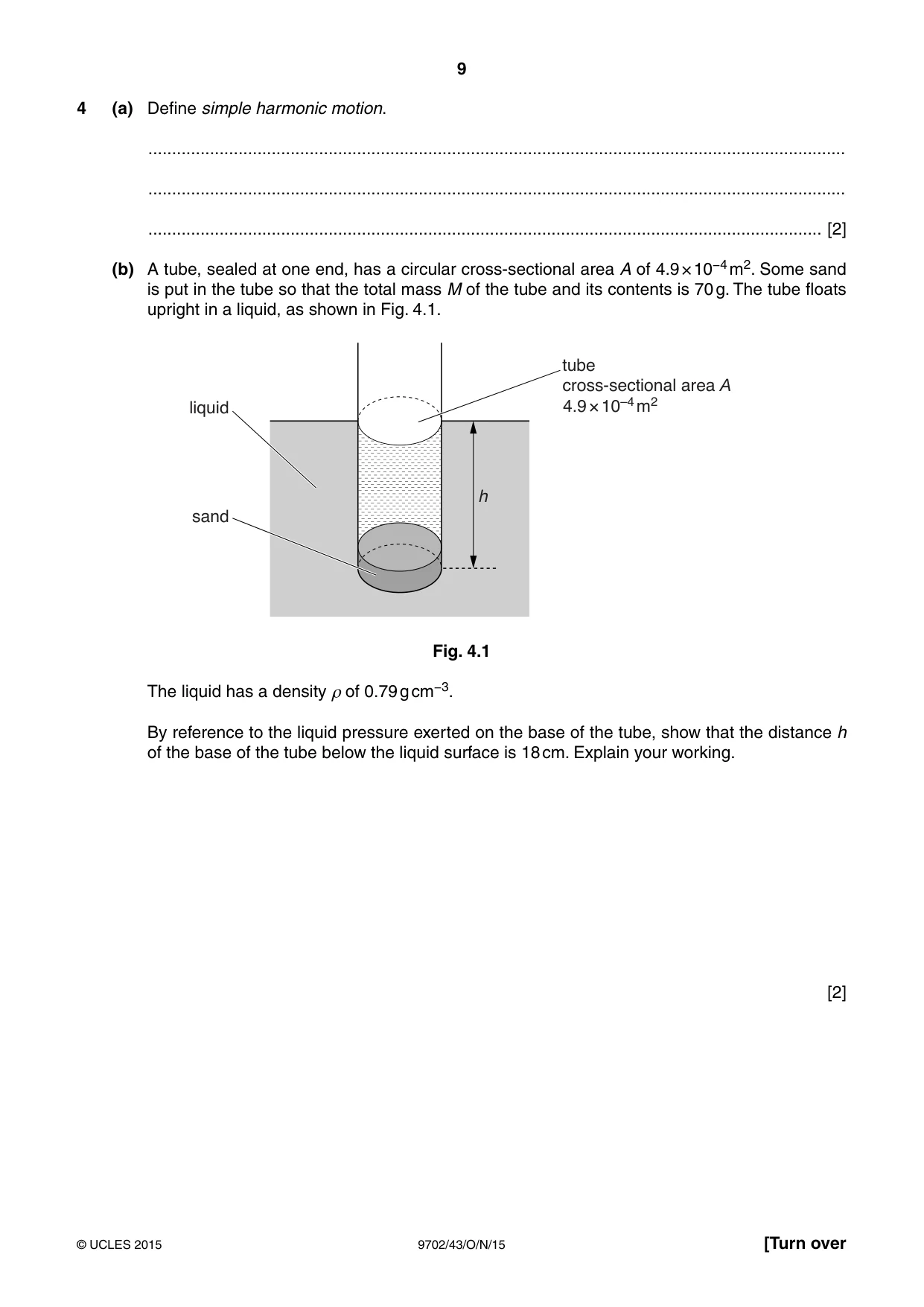
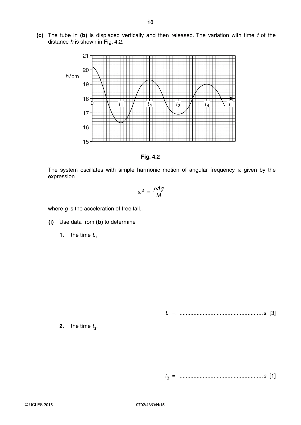
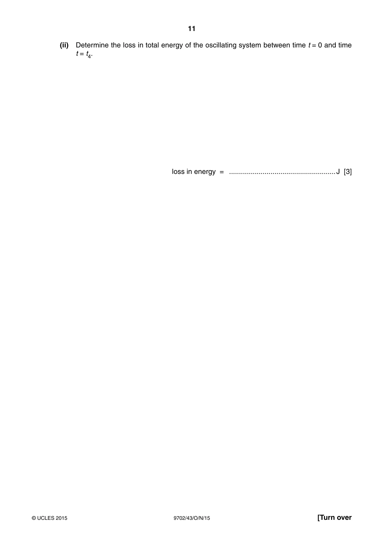
4 (a) Define simple harmonic motion. ................................................................................................................................................... ................................................................................................................................................... .............................................................................................................................................. [2] (b) A tube, sealed at one end, has a circular cross-sectional area A of 4.9 × 10⁻⁴ m2. Some sand is put in the tube so that the total mass M of the tube and its contents is 70 g. The tube floats upright in a liquid, as shown in Fig. 4.1. tube cross-sectional area A liquid 4.9 × 10⁻⁴ m2 h sand Fig. 4.1 The liquid has a density ρ of 0.79 g cm−3. By reference to the liquid pressure exerted on the base of the tube, show that the distance h of the base of the tube below the liquid surface is 18 cm. Explain your working. [2] (c) The tube in (b) is displaced vertically and then released. The variation with time t of the distance h is shown in Fig. 4.2. 21 20 h / cm 19 18 0 t 1 t 2 t 3 t 4 t 17 16 15 Fig. 4.2 The system oscillates with simple harmonic motion of angular frequency ω given by the expression ρAg ω2 = M where g is the acceleration of free fall. (i) Use data from (b) to determine 1. the time t1, t1 = ...................................................... s [3] 2. the time t3. t3 = ...................................................... s [1] (ii) Determine the loss in total energy of the oscillating system between time t = 0 and time t = t4. loss in energy = ...................................................... J [3]
Mark scheme: 4 (a) acceleration/force proportional to distance from a fixed point or displacement M1 either acceleration/force and displacement in opposite directions or acceleration/force (always) directed towards a fixed point/mean position/equilibrium position A1 [2] (b) hρ g = Mg / A B1 h × 790 × 4.9 × 10–4 = 70 × 10–3 leading to h = 0.18 m or 18 cm A1 [2] (c) (i) 1. ω2 = (790 × 4.9 × 10–4 × 9.81) / (70 × 10–3) C1 = 54.25 ω = 7.37 (rad s–1) period (= 2π / ω) = 0.85 s C1 t1 = 0.43 s A1 [3] 2. t3 = 1.28 s (allow 2 s.f.) A1 [1] (ii) energy of peak = ½Mω2x02 B1 change = ½ × 70 × 10–3 × 54.25 {(2.2 × 10⁻²)2 – (1.0 × 10⁻²)2} C1 = 7.3 × 10⁻⁴ J A1 [3]
Q5 · A positively charged solid metal sphere is isolated in space
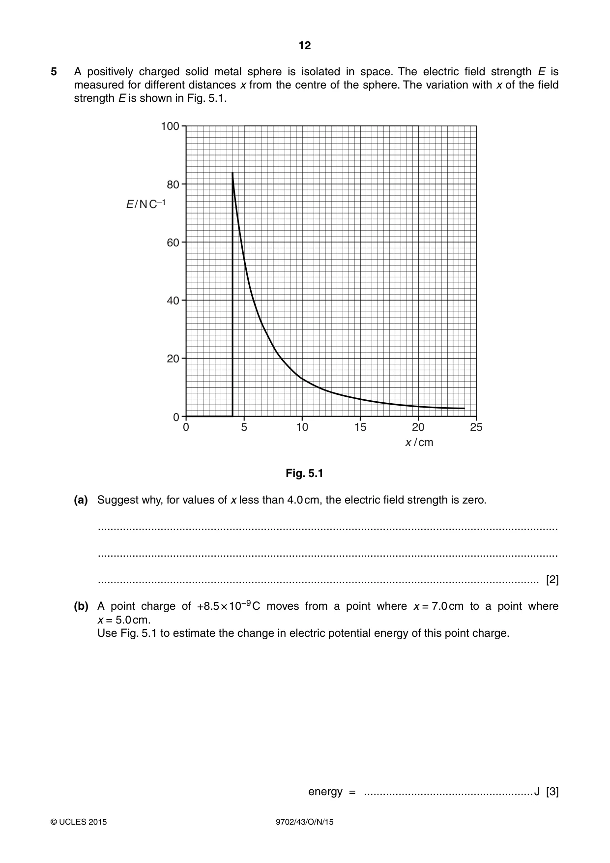
5 A positively charged solid metal sphere is isolated in space. The electric field strength E is measured for different distances x from the centre of the sphere. The variation with x of the field strength E is shown in Fig. 5.1. 100 80 E / N C–1 60 40 20 0 0 5 10 15 20 25 x / cm Fig. 5.1 (a) Suggest why, for values of x less than 4.0 cm, the electric field strength is zero. ................................................................................................................................................... ................................................................................................................................................... ............................................................................................................................................. [2] (b) A point charge of +8.5 × 10⁻⁹ C moves from a point where x = 7.0 cm to a point where x = 5.0 cm. Use Fig. 5.1 to estimate the change in electric potential energy of this point charge. energy = ...................................................... J [3]
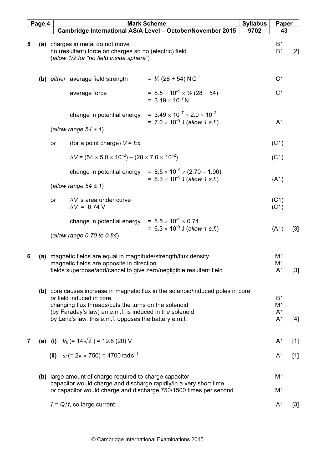
Mark scheme: 5 (a) charges in metal do not move B1 no (resultant) force on charges so no (electric) field B1 [2] (allow 1/2 for “no field inside sphere”) (b) either average field strength = ½ (28 + 54) N C–1 C1 average force = 8.5 × 10⁻⁹ × ½ (28 + 54) C1 = 3.49 × 10⁻⁷ N change in potential energy = 3.49 × 10–7 × 2.0 × 10–2 = 7.0 × 10⁻⁹ J (allow 1 s.f.) A1 (allow range 54 ± 1) or (for a point charge) V = Ex (C1) ∆V = (54 × 5.0 × 10–2) – (28 × 7.0 × 10–2) (C1) change in potential energy = 8.5 × 10–9 × (2.70 – 1.96) = 6.3 × 10⁻⁹ J (allow 1 s.f.) (A1) (allow range 54 ± 1) or ∆V is area under curve (C1) ∆V = 0.74 V (C1) change in potential energy = 8.5 × 10–9 × 0.74 = 6.3 × 10⁻⁹ J (allow 1 s.f.) (A1) [3] (allow range 0.70 to 0.84)
Q6 · Suggest an explanation for each of the following observations
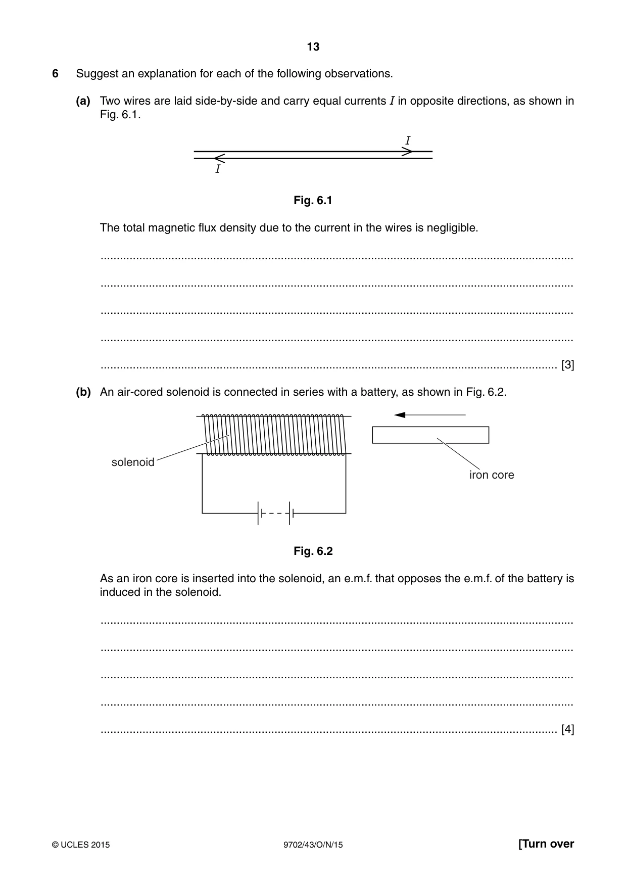
6 Suggest an explanation for each of the following observations. (a) Two wires are laid side-by-side and carry equal currents I in opposite directions, as shown in Fig. 6.1. I I Fig. 6.1 The total magnetic flux density due to the current in the wires is negligible. ................................................................................................................................................... ................................................................................................................................................... ................................................................................................................................................... ................................................................................................................................................... .............................................................................................................................................. [3] (b) An air-cored solenoid is connected in series with a battery, as shown in Fig. 6.2. solenoid iron core Fig. 6.2 As an iron core is inserted into the solenoid, an e.m.f. that opposes the e.m.f. of the battery is induced in the solenoid. ................................................................................................................................................... ................................................................................................................................................... ................................................................................................................................................... ................................................................................................................................................... .............................................................................................................................................. [4]
Mark scheme: 6 (a) magnetic fields are equal in magnitude/strength/flux density M1 magnetic fields are opposite in direction M1 fields superpose/add/cancel to give zero/negligible resultant field A1 [3] (b) core causes increase in magnetic flux in the solenoid/induced poles in core or field induced in core B1 changing flux threads/cuts the turns on the solenoid M1 (by Faraday’s law) an e.m.f. is induced in the solenoid A1 by Lenz’s law, this e.m.f. opposes the battery e.m.f. A1 [4]
Q7 · A student is using a power supply that produces a sinusoidal output
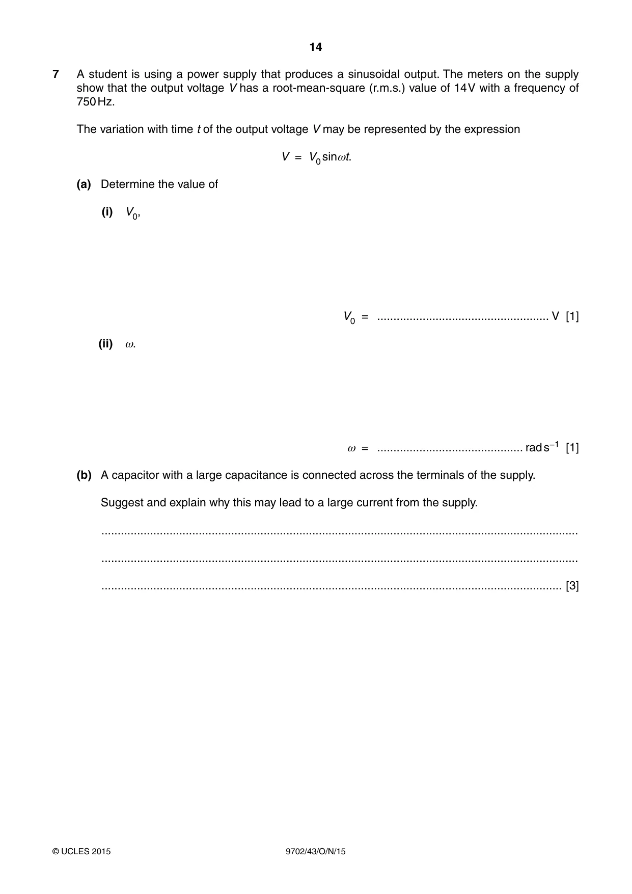
7 A student is using a power supply that produces a sinusoidal output. The meters on the supply show that the output voltage V has a root-mean-square (r.m.s.) value of 14 V with a frequency of 750 Hz. The variation with time t of the output voltage V may be represented by the expression V = V0 sinωt. (a) Determine the value of (i) V0, V0 = ..................................................... V [1] (ii) ω. ω = ............................................. rad s−1 [1] (b) A capacitor with a large capacitance is connected across the terminals of the supply. Suggest and explain why this may lead to a large current from the supply. ................................................................................................................................................... ................................................................................................................................................... .............................................................................................................................................. [3]
Mark scheme: 7 (a) (i) V0 (= 14 2 ) = 19.8 (20) V A1 [1] (ii) ω (= 2π × 750) = 4700 rad s–1 A1 [1] (b) large amount of charge required to charge capacitor M1 capacitor would charge and discharge rapidly/in a very short time or capacitor would charge and discharge 750/1500 times per second M1 I = Q / t, so large current A1 [3]
Q8 · Light of wavelength λ is incident on a metal surface having a work function energy Φ
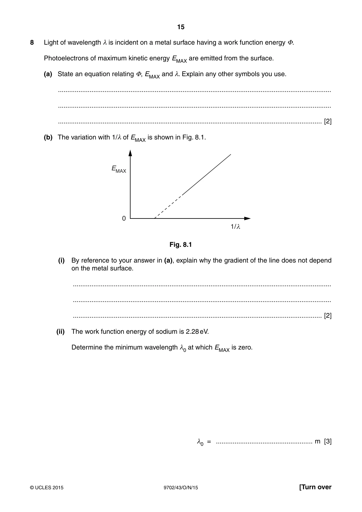
8 Light of wavelength λ is incident on a metal surface having a work function energy Φ. Photoelectrons of maximum kinetic energy EMAX are emitted from the surface. (a) State an equation relating Φ, EMAX and λ. Explain any other symbols you use. ................................................................................................................................................... ................................................................................................................................................... .............................................................................................................................................. [2] (b) The variation with 1/λ of EMAX is shown in Fig. 8.1. EMAX 0 1/ h Fig. 8.1 (i) By reference to your answer in (a), explain why the gradient of the line does not depend on the metal surface. ........................................................................................................................................... ........................................................................................................................................... ...................................................................................................................................... [2] (ii) The work function energy of sodium is 2.28 eV. Determine the minimum wavelength λ0 at which EMAX is zero. λ0 = .................................................... m [3]
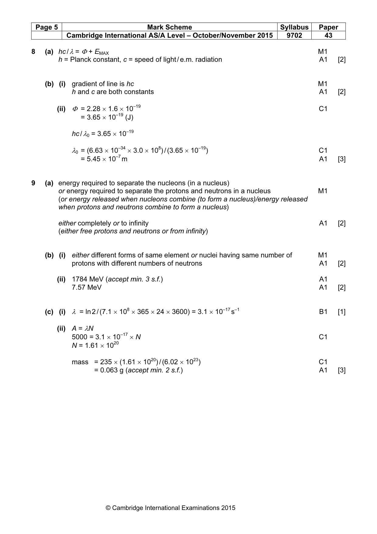
Mark scheme: 8 (a) hc / λ = Φ + EMAX M1 h = Planck constant, c = speed of light / e.m. radiation A1 [2] (b) (i) gradient of line is hc M1 h and c are both constants A1 [2] (ii) Φ = 2.28 × 1.6 × 10–19 C1 = 3.65 × 10⁻¹⁹ (J) hc / λ0 = 3.65 × 10⁻¹⁹ λ0 = (6.63 × 10–34 × 3.0 × 108) / (3.65 × 10⁻¹⁹) C1 = 5.45 × 10⁻⁷ m A1 [3]
Q9 · State what is meant by the binding energy of a nucleus
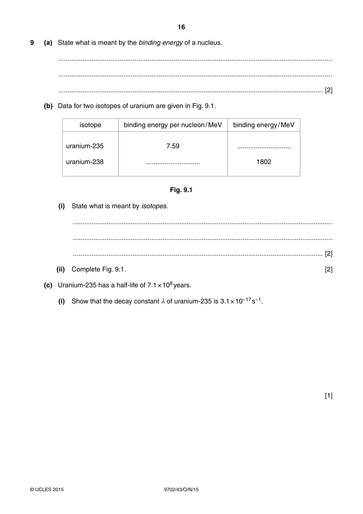
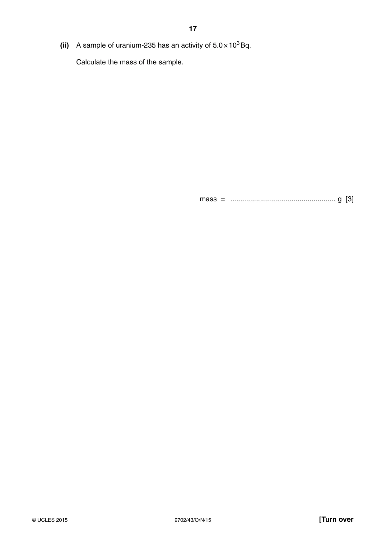
9 (a) State what is meant by the binding energy of a nucleus. ................................................................................................................................................... ................................................................................................................................................... .............................................................................................................................................. [2] (b) Data for two isotopes of uranium are given in Fig. 9.1. isotope binding energy per nucleon / MeV binding energy / MeV uranium-235 7.59 ............................. uranium-238 ............................. 1802 Fig. 9.1 (i) State what is meant by isotopes. ........................................................................................................................................... ........................................................................................................................................... ...................................................................................................................................... [2] (ii) Complete Fig. 9.1. [2] (c) Uranium-235 has a half-life of 7.1 × 10⁸ years. (i) Show that the decay constant λ of uranium-235 is 3.1 × 10⁻¹⁷ s−1. [1] (ii) A sample of uranium-235 has an activity of 5.0 × 10³ Bq. Calculate the mass of the sample. mass = ..................................................... g [3]
Mark scheme: 9 (a) energy required to separate the nucleons (in a nucleus) or energy required to separate the protons and neutrons in a nucleus M1 (or energy released when nucleons combine (to form a nucleus)/energy released when protons and neutrons combine to form a nucleus) either completely or to infinity A1 [2] (either free protons and neutrons or from infinity) (b) (i) either different forms of same element or nuclei having same number of M1 protons with different numbers of neutrons A1 [2] (ii) 1784 MeV (accept min. 3 s.f.) A1 7.57 MeV A1 [2] (c) (i) λ = ln 2 / (7.1 × 108 × 365 × 24 × 3600) = 3.1 × 10⁻¹⁷ s–1 B1 [1] (ii) A = λN 5000 = 3.1 × 10⁻¹⁷ × N C1 N = 1.61 × 10²⁰ mass = 235 × (1.61 × 1020) / (6.02 × 10²³) C1 = 0.063 g (accept min. 2 s.f.) A1 [3] Section B
Q10 · The output potential VOUT from an operational amplifier is to be monitored using an…
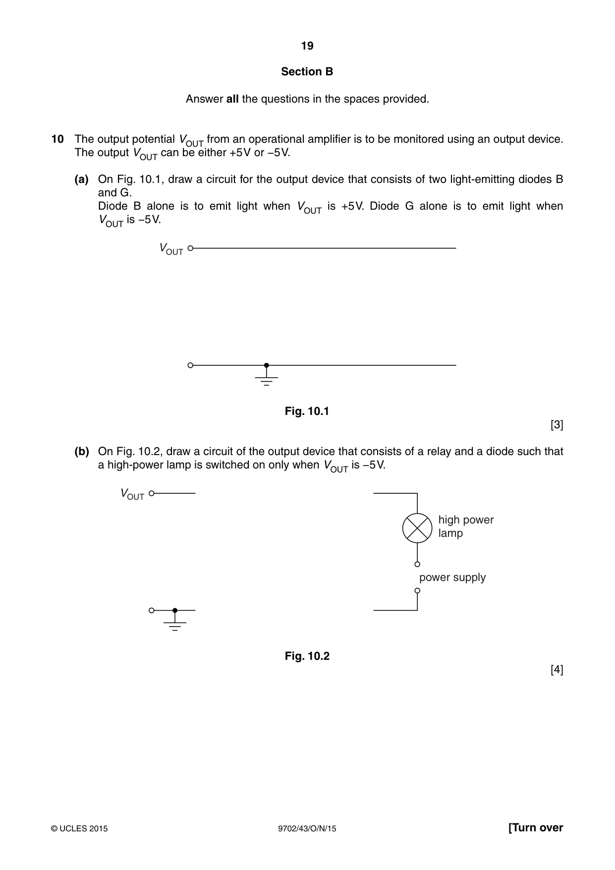
10 The output potential VOUT from an operational amplifier is to be monitored using an output device. The output VOUT can be either +5 V or −5 V. (a) On Fig. 10.1, draw a circuit for the output device that consists of two light-emitting diodes B and G. Diode B alone is to emit light when VOUT is +5 V. Diode G alone is to emit light when VOUT is −5 V. VOUT Fig. 10.1 [3] (b) On Fig. 10.2, draw a circuit of the output device that consists of a relay and a diode such that a high-power lamp is switched on only when VOUT is −5 V. VOUT high power lamp power supply Fig. 10.2 [4]
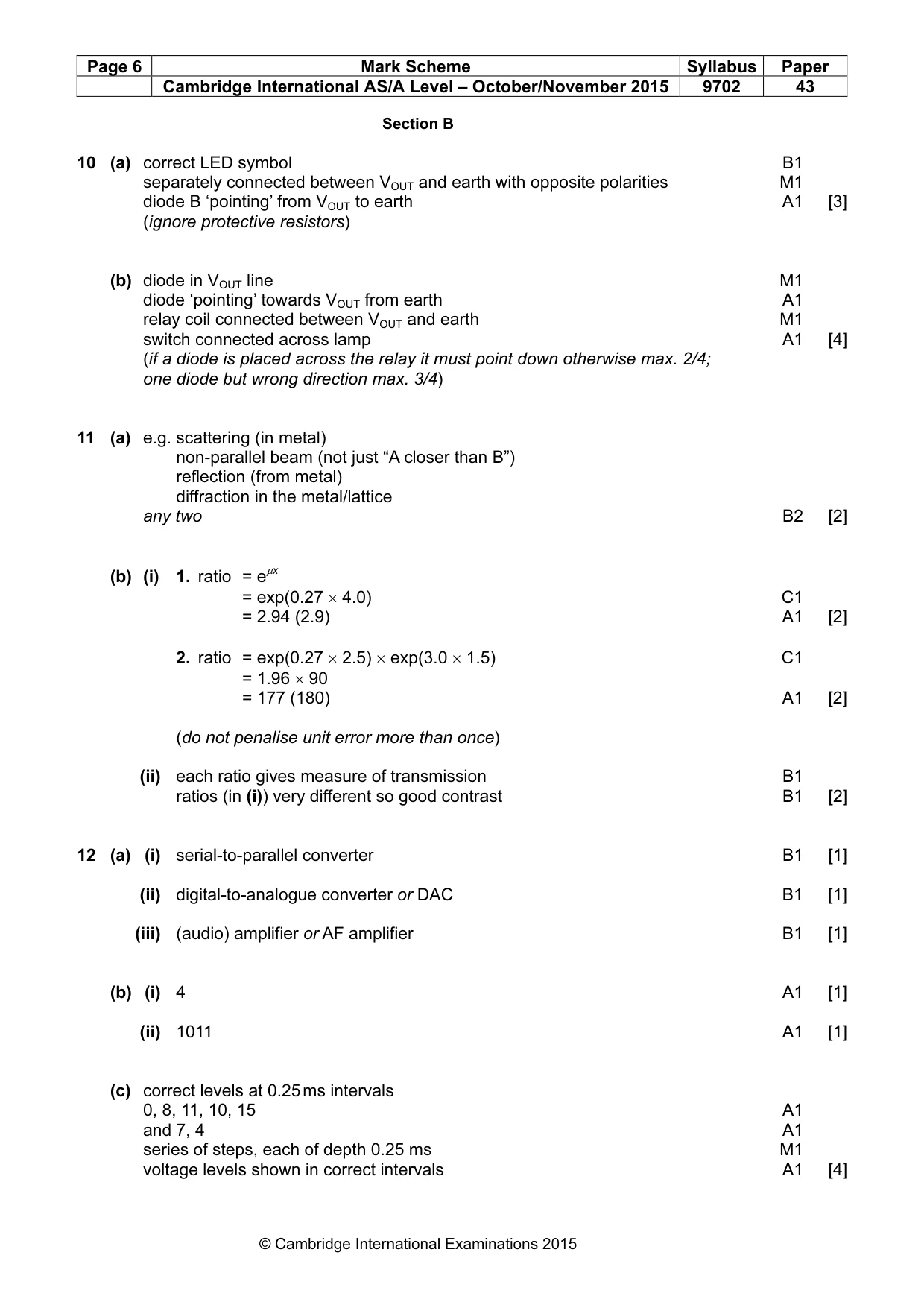
Mark scheme: 10 (a) correct LED symbol B1 separately connected between VOUT and earth with opposite polarities M1 diode B ‘pointing’ from VOUT to earth A1 [3] (ignore protective resistors) (b) diode in VOUT line M1 diode ‘pointing’ towards VOUT from earth A1 relay coil connected between VOUT and earth M1 switch connected across lamp A1 [4] (if a diode is placed across the relay it must point down otherwise max. 2/4; one diode but wrong direction max. 3/4)
Q11 · An X-ray source is placed on one side of a metal plate, as shown in Fig
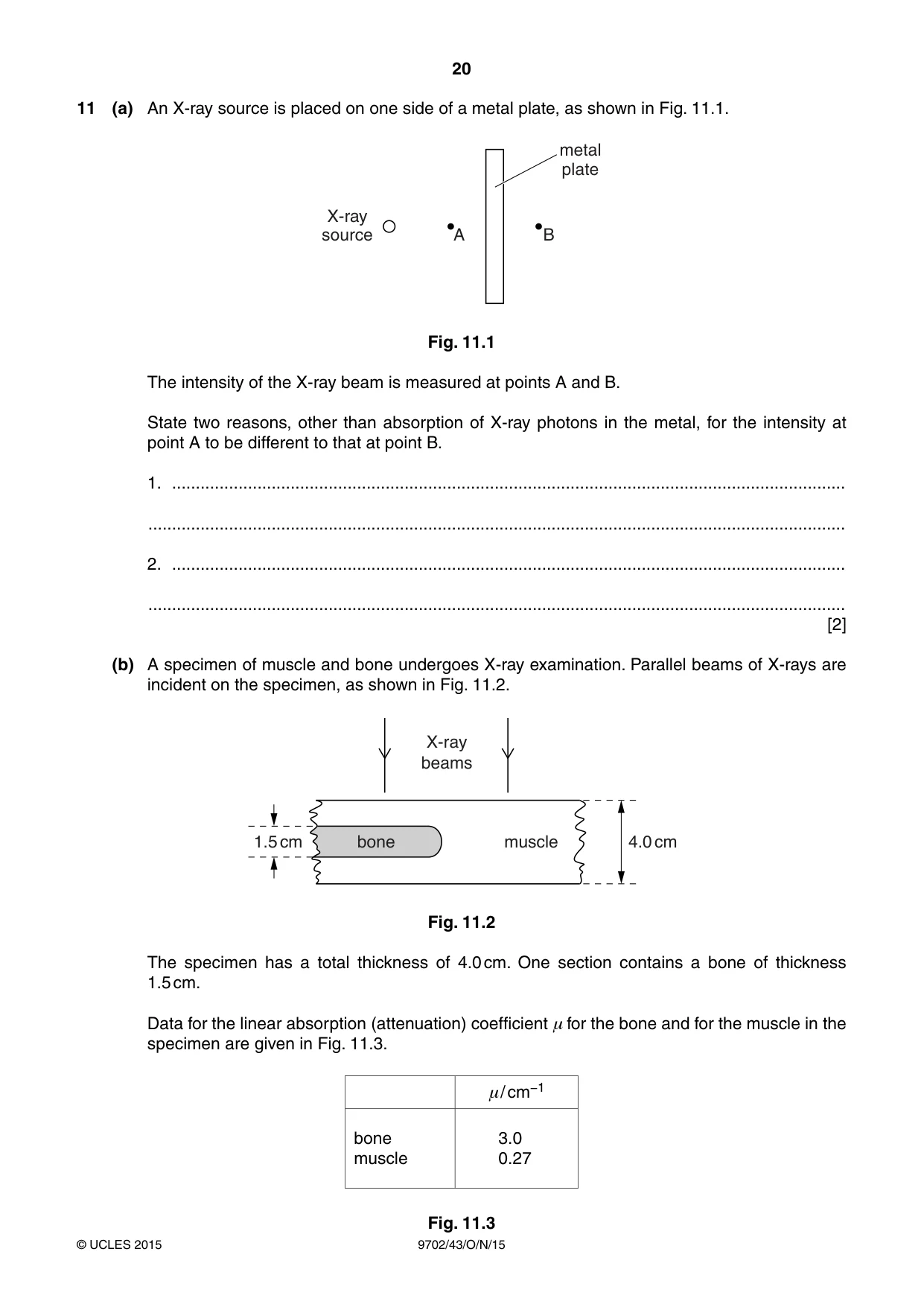
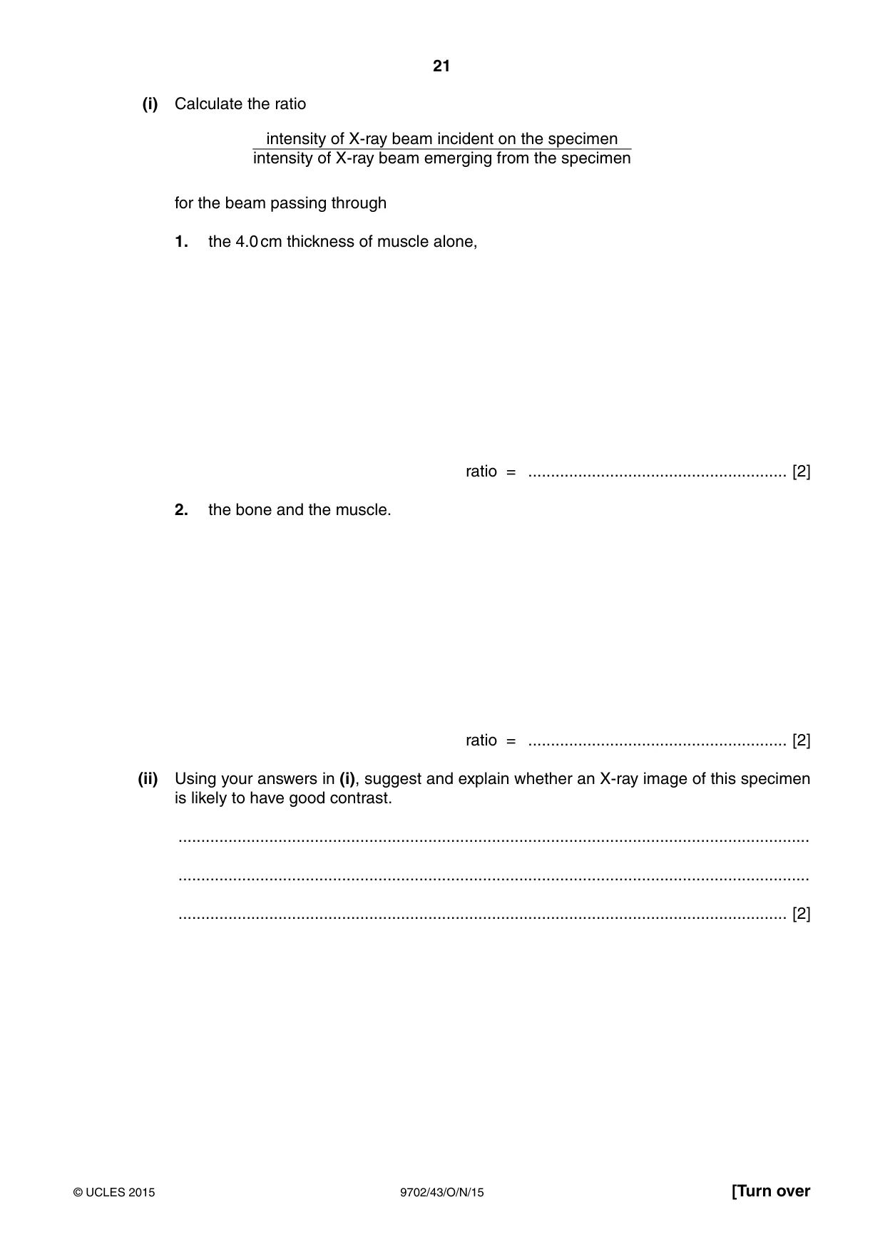
11 (a) An X-ray source is placed on one side of a metal plate, as shown in Fig. 11.1. metal plate X-ray source A B Fig. 11.1 The intensity of the X-ray beam is measured at points A and B. State two reasons, other than absorption of X-ray photons in the metal, for the intensity at point A to be different to that at point B. 1. .............................................................................................................................................. ................................................................................................................................................... 2. .............................................................................................................................................. ................................................................................................................................................... [2] (b) A specimen of muscle and bone undergoes X-ray examination. Parallel beams of X-rays are incident on the specimen, as shown in Fig. 11.2. X-ray beams 1.5 cm bone muscle 4.0 cm Fig. 11.2 The specimen has a total thickness of 4.0 cm. One section contains a bone of thickness 1.5 cm. Data for the linear absorption (attenuation) coefficient μ for the bone and for the muscle in the specimen are given in Fig. 11.3. μ/ cm−1 bone 3.0 muscle 0.27 Fig. 11.3 (i) Calculate the ratio intensity of X-ray beam incident on the specimen intensity of X-ray beam emerging from the specimen for the beam passing through 1. the 4.0 cm thickness of muscle alone, ratio = ......................................................... [2] 2. the bone and the muscle. ratio = ......................................................... [2] (ii) Using your answers in (i), suggest and explain whether an X-ray image of this specimen is likely to have good contrast. ........................................................................................................................................... ........................................................................................................................................... ...................................................................................................................................... [2]
Mark scheme: 11 (a) e.g. scattering (in metal) non-parallel beam (not just “A closer than B”) reflection (from metal) diffraction in the metal/lattice any two B2 [2] (b) (i) 1. ratio = eµx = exp(0.27 × 4.0) C1 = 2.94 (2.9) A1 [2] 2. ratio = exp(0.27 × 2.5) × exp(3.0 × 1.5) C1 = 1.96 × 90 = 177 (180) A1 [2] (do not penalise unit error more than once) (ii) each ratio gives measure of transmission B1 ratios (in (i)) very different so good contrast B1 [2]
Q12 · A transmission system for speech may be represented by the block diagram of Fig
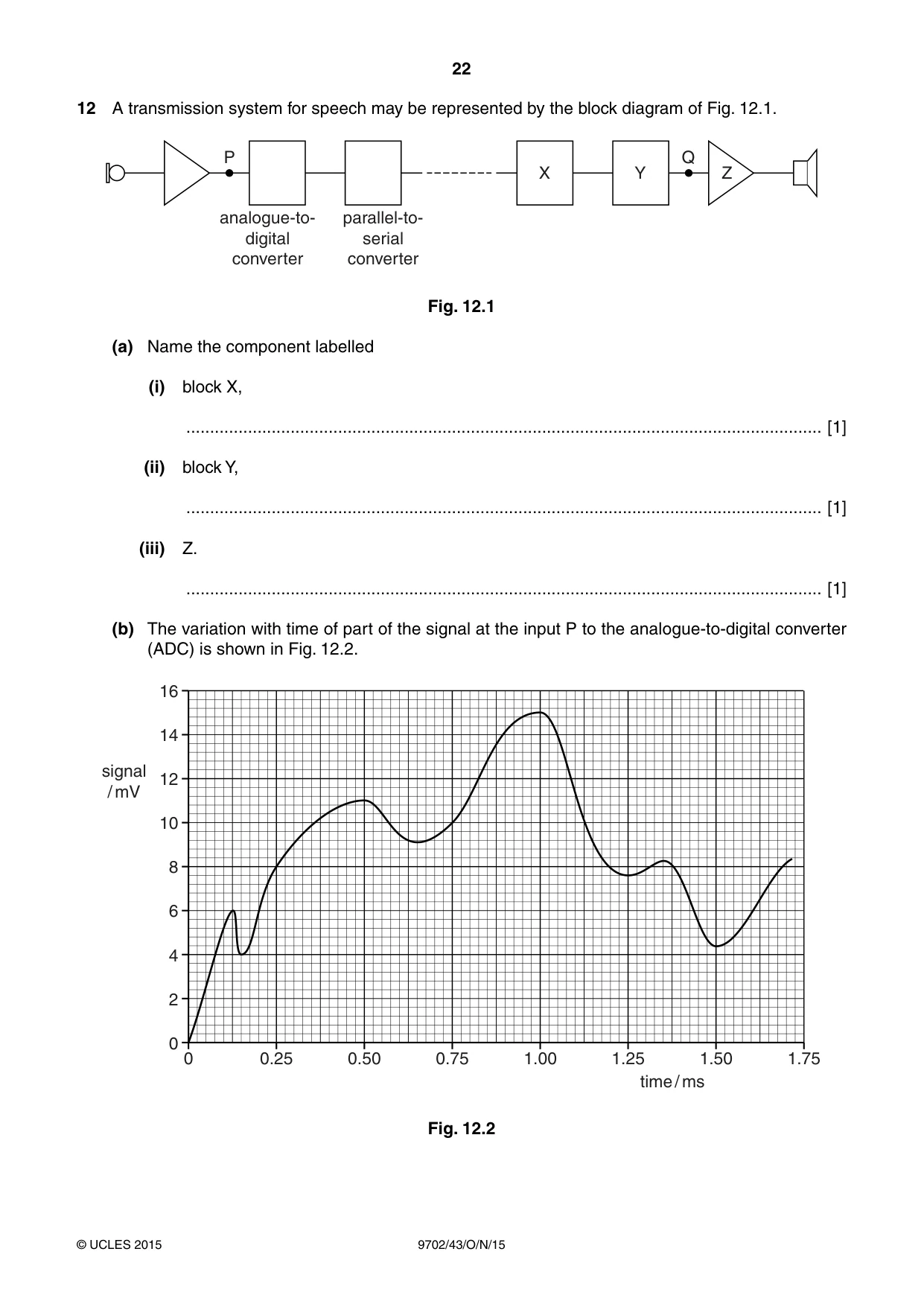
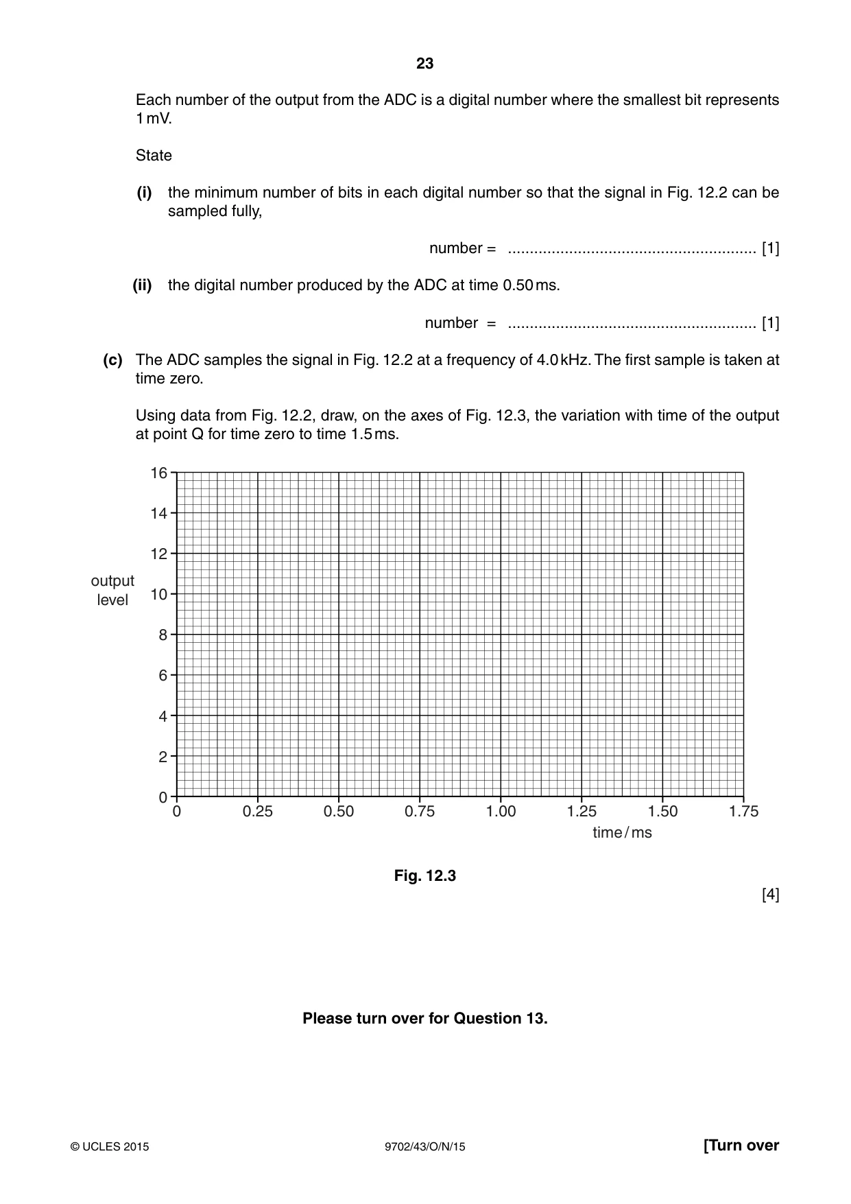
12 A transmission system for speech may be represented by the block diagram of Fig. 12.1. P Q X Y Z analogue-to- parallel-to- digital serial converter converter Fig. 12.1 (a) Name the component labelled (i) block X, ...................................................................................................................................... [1] (ii) block Y, ...................................................................................................................................... [1] (iii) Z. ...................................................................................................................................... [1] (b) The variation with time of part of the signal at the input P to the analogue-to-digital converter (ADC) is shown in Fig. 12.2. 16 14 signal 12 / mV 10 8 6 4 2 0 0 0.25 0.50 0.75 1.00 1.25 1.50 1.75 time / ms Fig. 12.2 Each number of the output from the ADC is a digital number where the smallest bit represents 1 mV. State (i) the minimum number of bits in each digital number so that the signal in Fig. 12.2 can be sampled fully, number = ......................................................... [1] (ii) the digital number produced by the ADC at time 0.50 ms. number = ......................................................... [1] (c) The ADC samples the signal in Fig. 12.2 at a frequency of 4.0 kHz. The first sample is taken at time zero. Using data from Fig. 12.2, draw, on the axes of Fig. 12.3, the variation with time of the output at point Q for time zero to time 1.5 ms. 16 14 12 output 10 level 8 6 4 2 0 0 0.25 0.50 0.75 1.00 1.25 1.50 1.75 time / ms Fig. 12.3 [4] Please turn over for Question 13.
Mark scheme: 12 (a) (i) serial-to-parallel converter B1 [1] (ii) digital-to-analogue converter or DAC B1 [1] (iii) (audio) amplifier or AF amplifier B1 [1] (b) (i) 4 A1 [1] (ii) 1011 A1 [1] (c) correct levels at 0.25 ms intervals 0, 8, 11, 10, 15 A1 and 7, 4 A1 series of steps, each of depth 0.25 ms M1 voltage levels shown in correct intervals A1 [4]
Q13 · Polar orbiting satellites have orbits over the poles of the Earth
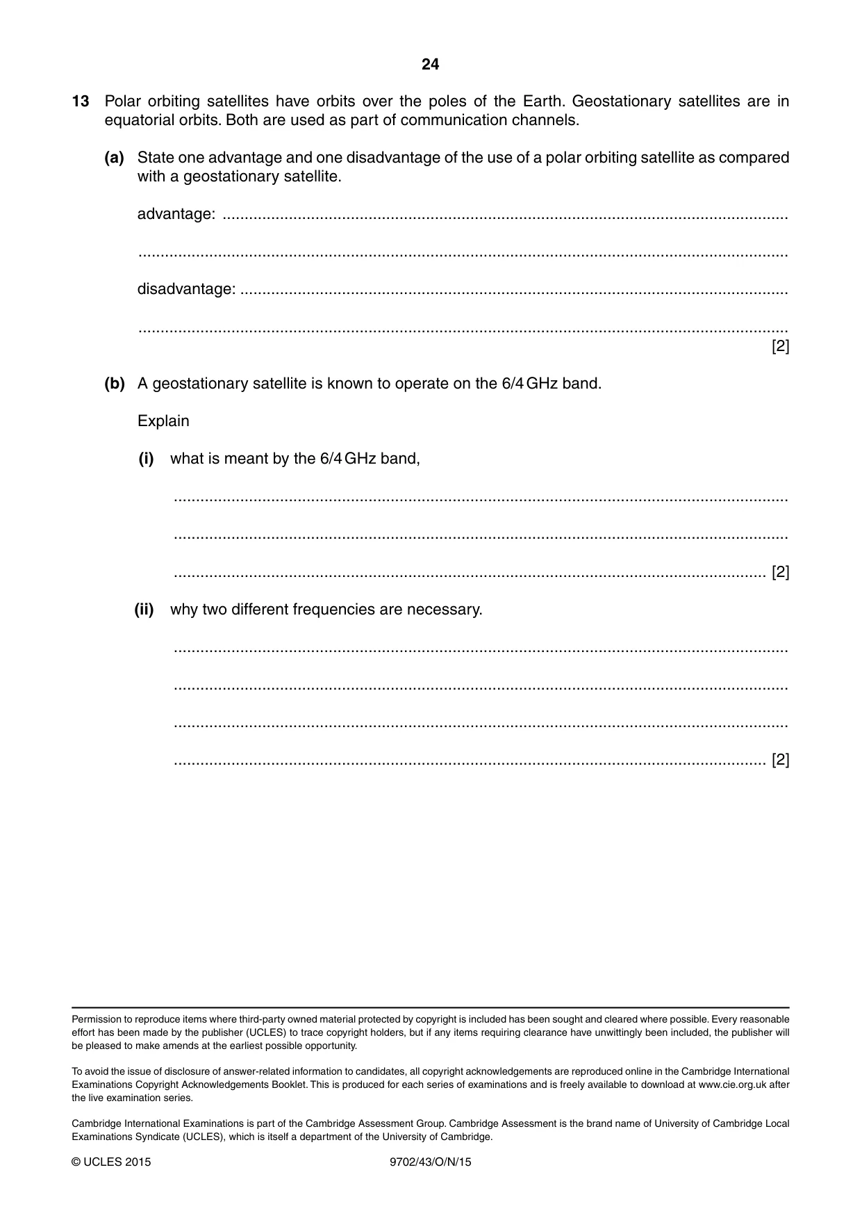
13 Polar orbiting satellites have orbits over the poles of the Earth. Geostationary satellites are in equatorial orbits. Both are used as part of communication channels. (a) State one advantage and one disadvantage of the use of a polar orbiting satellite as compared with a geostationary satellite. advantage: ................................................................................................................................ ................................................................................................................................................... disadvantage: ............................................................................................................................ ................................................................................................................................................... [2] (b) A geostationary satellite is known to operate on the 6/4 GHz band. Explain (i) what is meant by the 6/4 GHz band, ........................................................................................................................................... ........................................................................................................................................... ...................................................................................................................................... [2] (ii) why two different frequencies are necessary. ........................................................................................................................................... ........................................................................................................................................... ........................................................................................................................................... ...................................................................................................................................... [2]
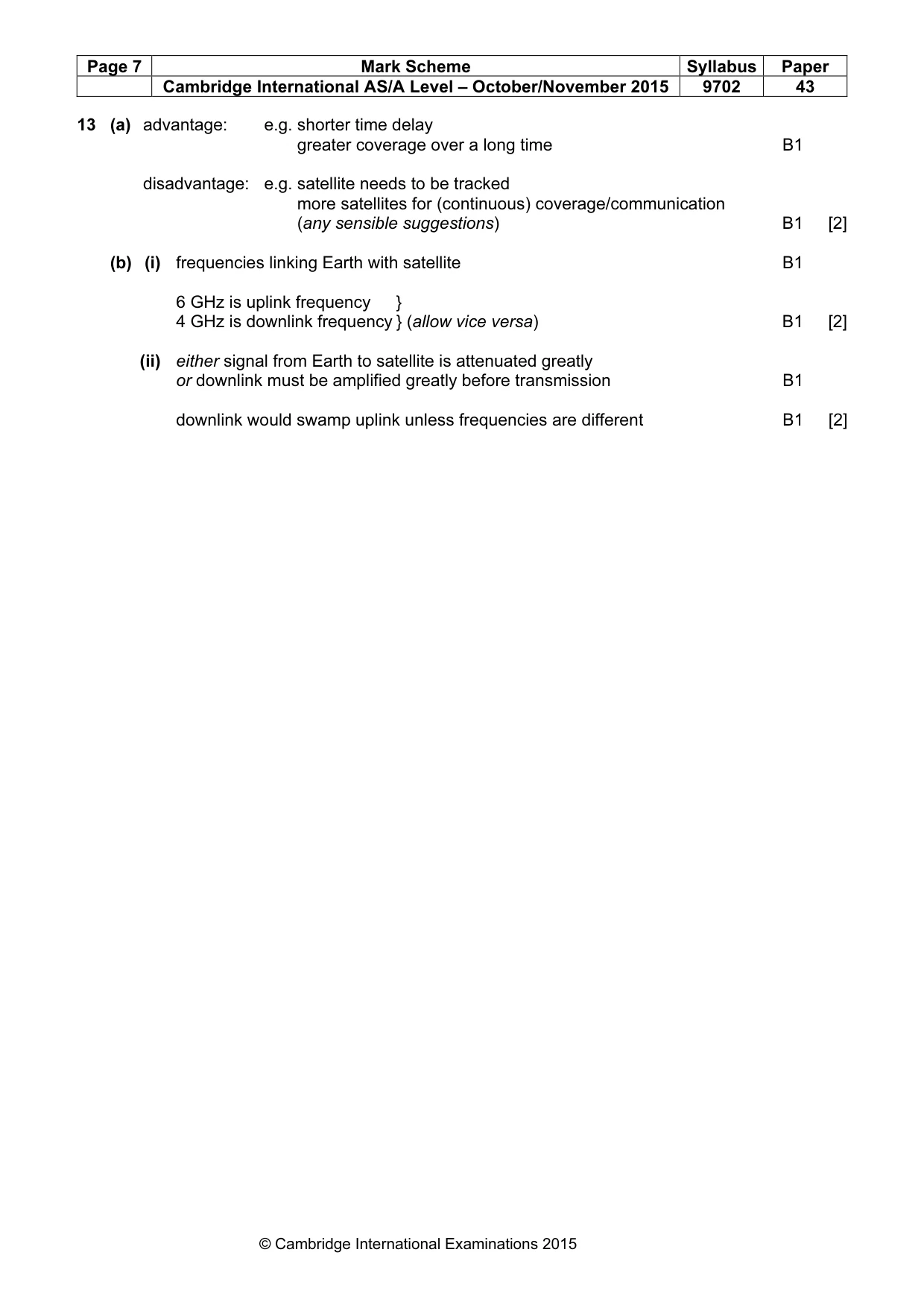
Mark scheme: 13 (a) advantage: e.g. shorter time delay greater coverage over a long time B1 disadvantage: e.g. satellite needs to be tracked more satellites for (continuous) coverage/communication (any sensible suggestions) B1 [2] (b) (i) frequencies linking Earth with satellite B1 6 GHz is uplink frequency } 4 GHz is downlink frequency } (allow vice versa) B1 [2] (ii) either signal from Earth to satellite is attenuated greatly or downlink must be amplified greatly before transmission B1 downlink would swamp uplink unless frequencies are different B1 [2]
What was in this paper
The subtopics covered by these 13 questions, and how many questions each got. Open one in a new tab to see every Cambridge question on it.
2Characteristics of alternating currents1Electric potential1Electromagnetic induction1Electromagnetic spectrum1Gravitational field of a point mass1Kinetic theory of gases1Mass defect and nuclear binding energy1Photoelectric effect1Production and use of X-rays1Simple harmonic oscillations1Temperature scales1What you needed in this session
Cambridge’s own grade thresholds for 2015 Oct/Nov, Paper 4 · Variant 3. A higher threshold means an easier paper — the bar moves with how the cohort did.