Cambridge IGCSE Physics (9-1) 0972 — 2019 Oct/Nov Paper 3 · Variant 1
0972/31/O/N/19 · 12 questions · 80 marks · ≈90 min
The question paper and its mark scheme, free to read here and free to download. This is Cambridge’s own paper, exactly as it was sat.
Question paper20 pages
Mark scheme11 pages
Answers below. Sit the paper first if you are practising.
Questions as text
Q1 · A plastic water barrel
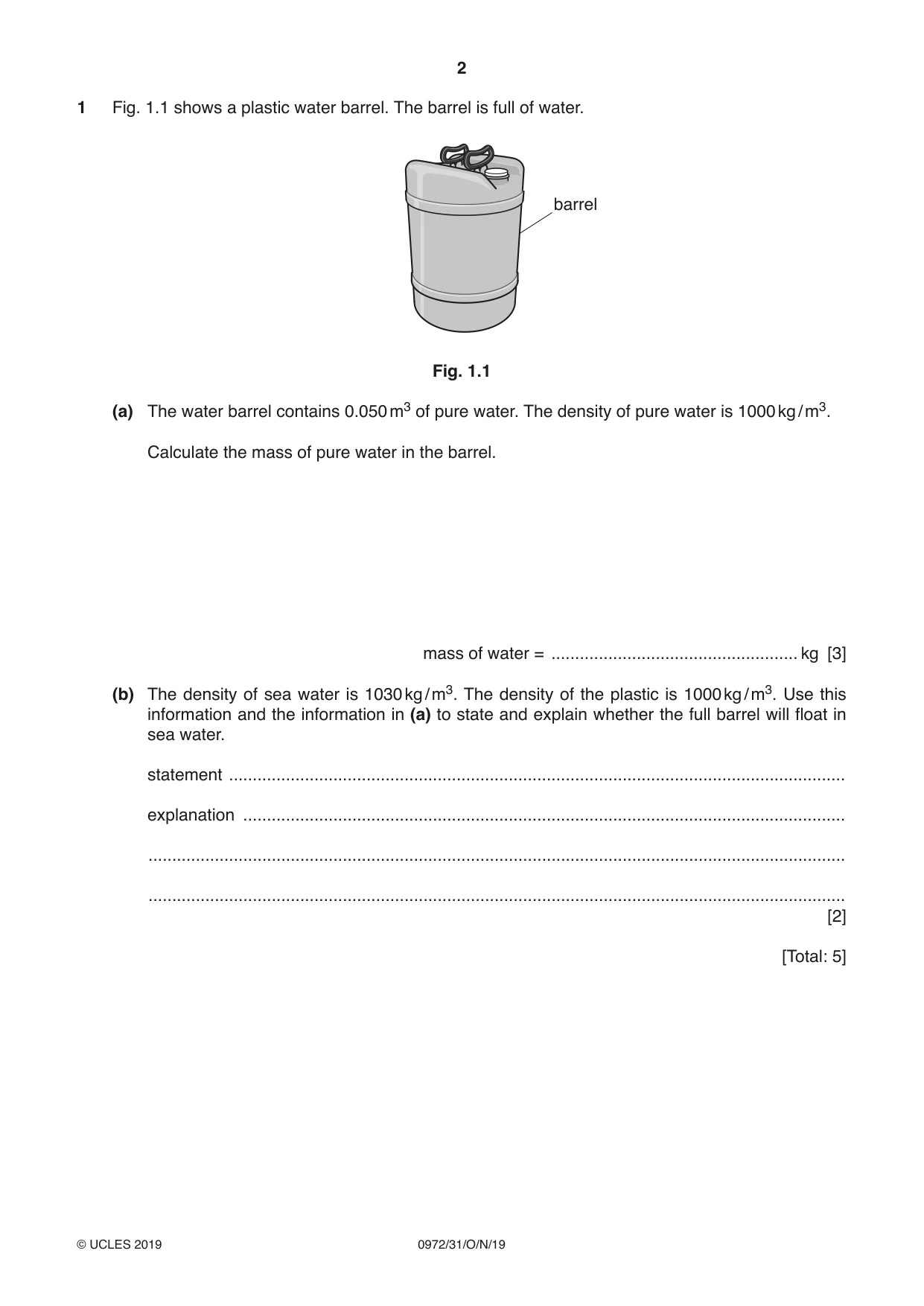
1 Fig. 1.1 shows a plastic water barrel. The barrel is full of water. barrel Fig. 1.1 (a) The water barrel contains 0.050 m3 of pure water. The density of pure water is 1000 kg / m3. Calculate the mass of pure water in the barrel. mass of water = .................................................... kg [3] (b) The density of sea water is 1030 kg / m3. The density of the plastic is 1000 kg / m3. Use this information and the information in (a) to state and explain whether the full barrel will float in sea water. statement .................................................................................................................................. explanation ............................................................................................................................... ................................................................................................................................................... ................................................................................................................................................... [2] [Total: 5]
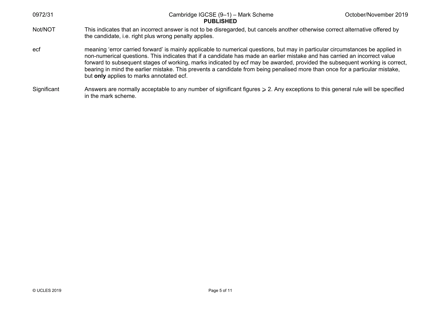
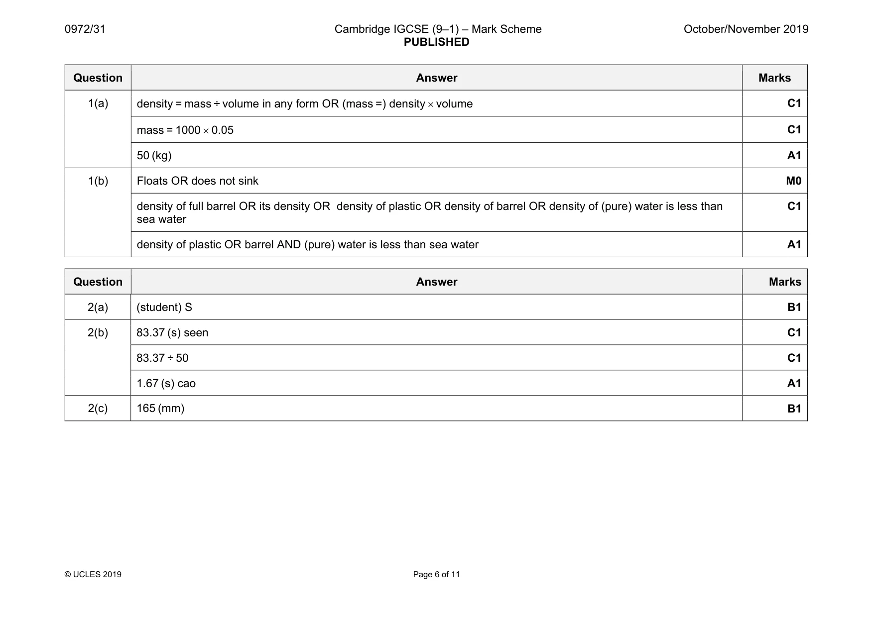
Mark scheme: 1(a) C1 mass = 1000 × 0.05 C1 50 (kg) A1 1(b) Floats OR does not sink M0 density of full barrel OR its density OR density of plastic OR density of barrel OR density of (pure) water is less than sea water C1 density of plastic OR barrel AND (pure) water is less than sea water A1
Q2 · Four students P, Q, R and S each attempt to measure the time period (the time for one…
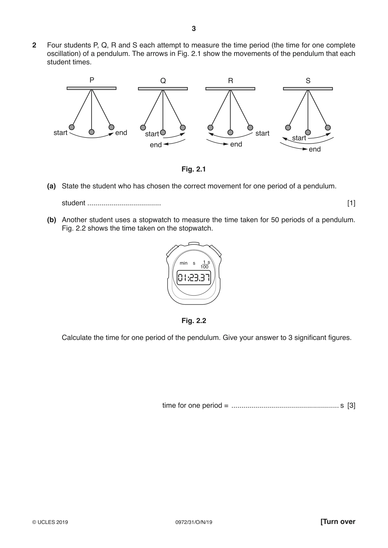
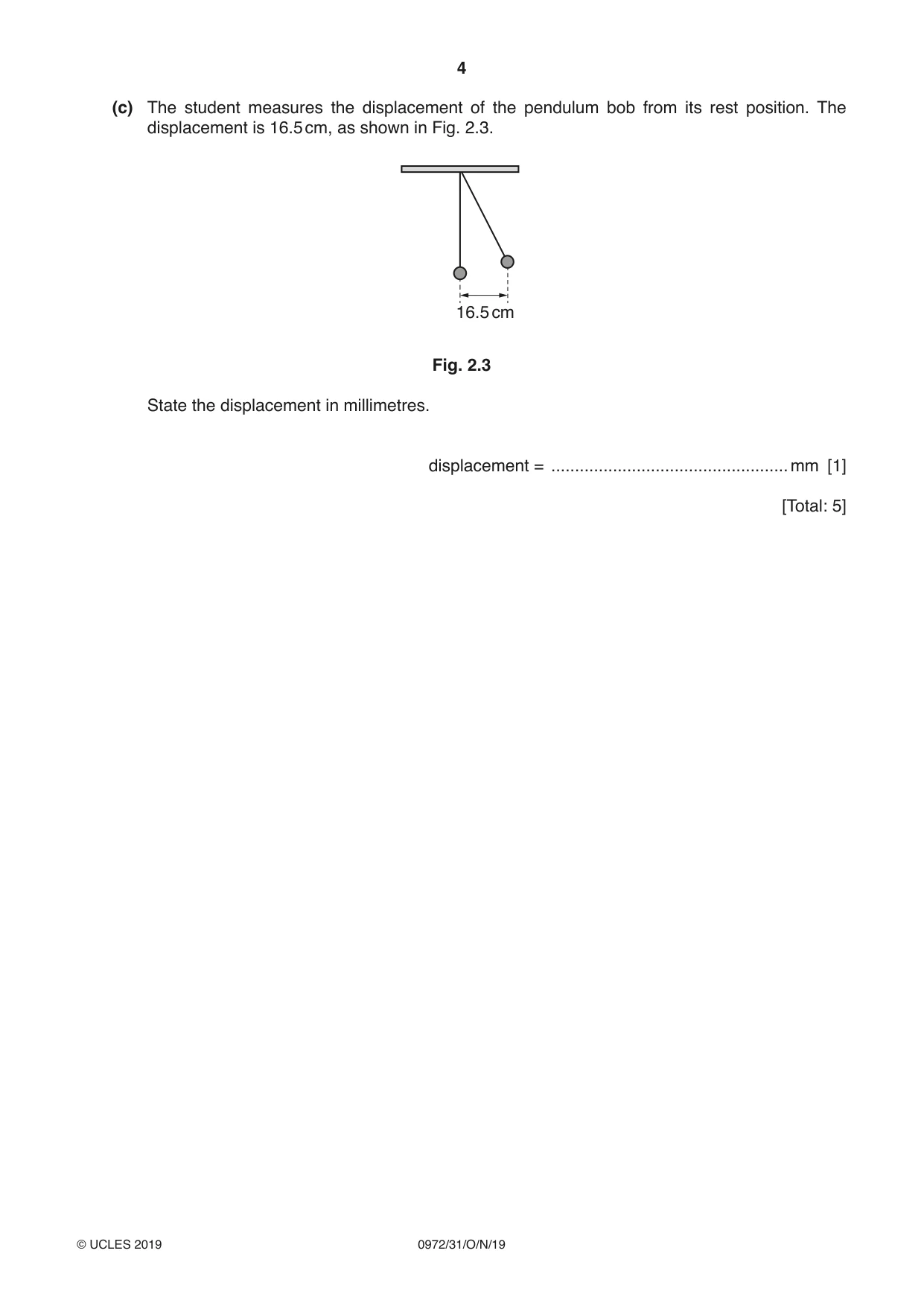
2 Four students P, Q, R and S each attempt to measure the time period (the time for one complete oscillation) of a pendulum. The arrows in Fig. 2.1 show the movements of the pendulum that each student times. P Q R S start end start start start end end end Fig. 2.1 (a) State the student who has chosen the correct movement for one period of a pendulum. student ..................................... [1] (b) Another student uses a stopwatch to measure the time taken for 50 periods of a pendulum. Fig. 2.2 shows the time taken on the stopwatch. min s 1 s 100 01:23.37 Fig. 2.2 Calculate the time for one period of the pendulum. Give your answer to 3 significant figures. time for one period = ...................................................... s [3] (c) The student measures the displacement of the pendulum bob from its rest position. The displacement is 16.5 cm, as shown in Fig. 2.3. 16.5 cm Fig. 2.3 State the displacement in millimetres. displacement = ..................................................mm [1] [Total: 5]
Mark scheme: 2(a) (student) S B1 2(b) 83.37 (s) seen C1 83.37 ÷ 50 C1 1.67 (s) cao A1 2(c) 165 (mm) B1
More questions on Physical quantities and measurement techniques
Q3 · A spring with no load attached
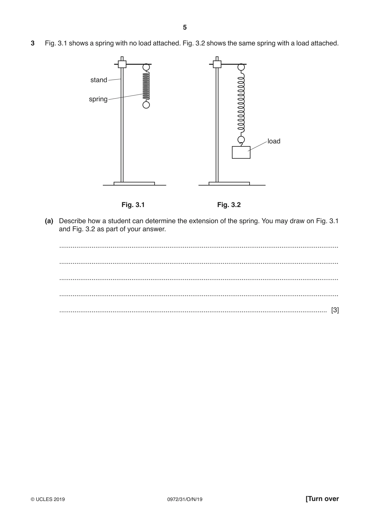
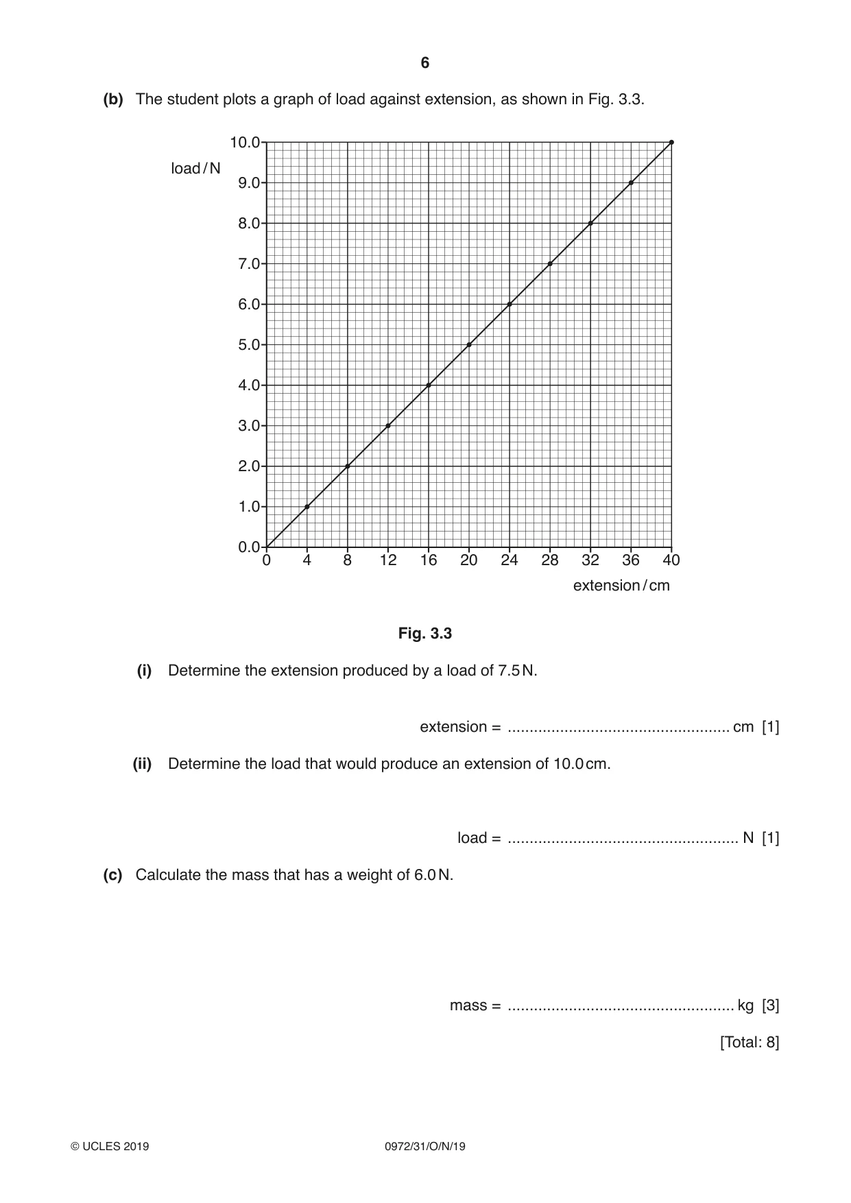
3 Fig. 3.1 shows a spring with no load attached. Fig. 3.2 shows the same spring with a load attached. stand spring load Fig. 3.1 Fig. 3.2 (a) Describe how a student can determine the extension of the spring. You may draw on Fig. 3.1 and Fig. 3.2 as part of your answer. ................................................................................................................................................... ................................................................................................................................................... ................................................................................................................................................... ................................................................................................................................................... ............................................................................................................................................. [3] (b) The student plots a graph of load against extension, as shown in Fig. 3.3. 10.0 load / N 9.0 8.0 7.0 6.0 5.0 4.0 3.0 2.0 1.0 0.0 0 4 8 12 16 20 24 28 32 36 40 extension / cm Fig. 3.3 (i) Determine the extension produced by a load of 7.5 N. extension = ................................................... cm [1] (ii) Determine the load that would produce an extension of 10.0 cm. load = ..................................................... N [1] (c) Calculate the mass that has a weight of 6.0 N. mass = .................................................... kg [3] [Total: 8]
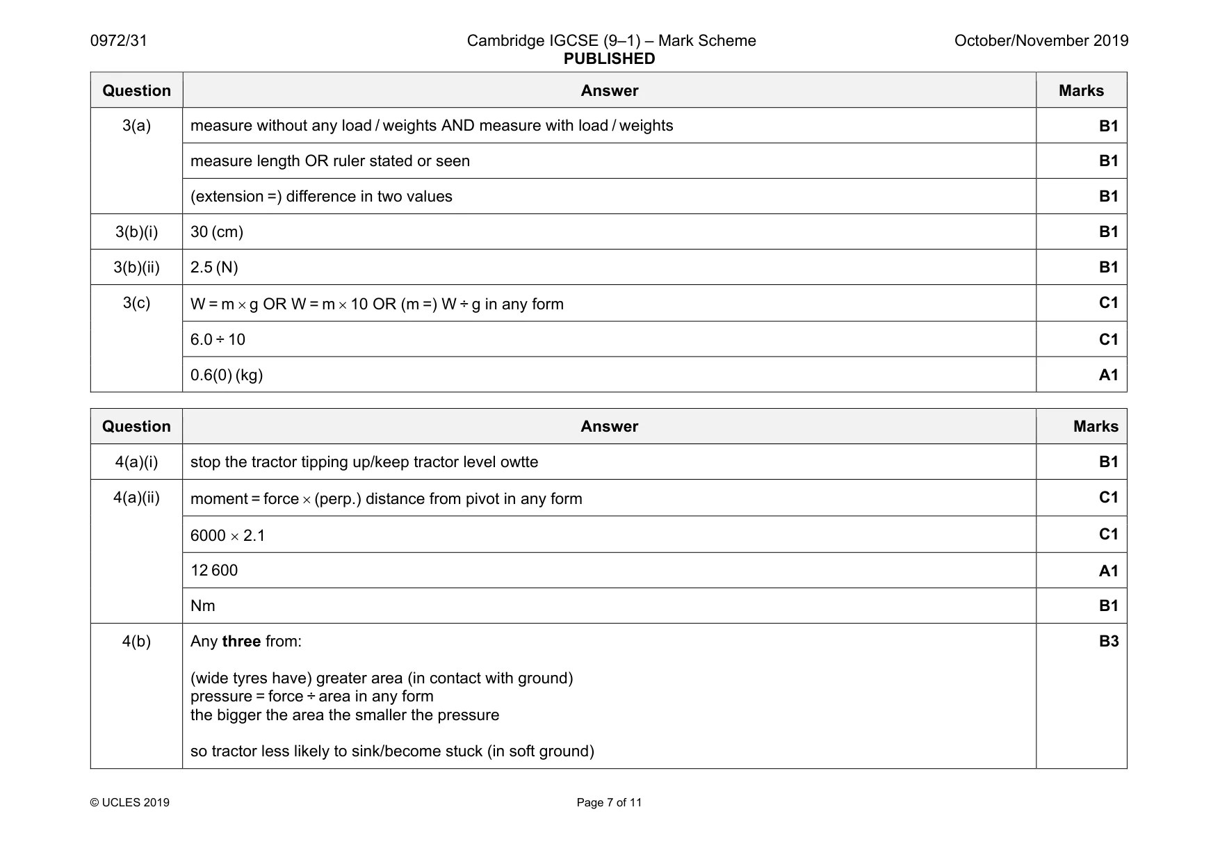
Mark scheme: 3(a) measure without any load / weights AND measure with load / weights B1 measure length OR ruler stated or seen B1 (extension =) difference in two values B1 3(b)(i) 30 (cm) B1 3(b)(ii) 2.5 (N) B1 3(c) W = m × g OR W = m × 10 OR (m =) W ÷ g in any form C1 6.0 ÷ 10 C1 0.6(0) (kg) A1
Q4 · A tractor fitted with a device for breaking up soil in a field
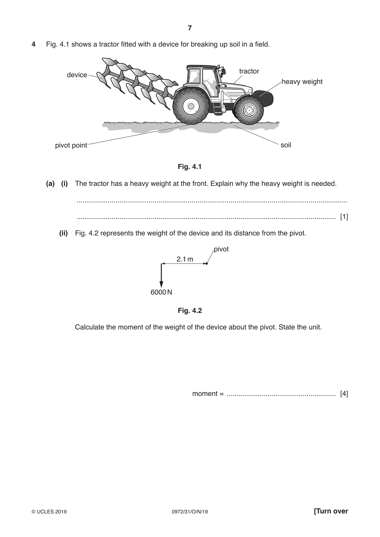
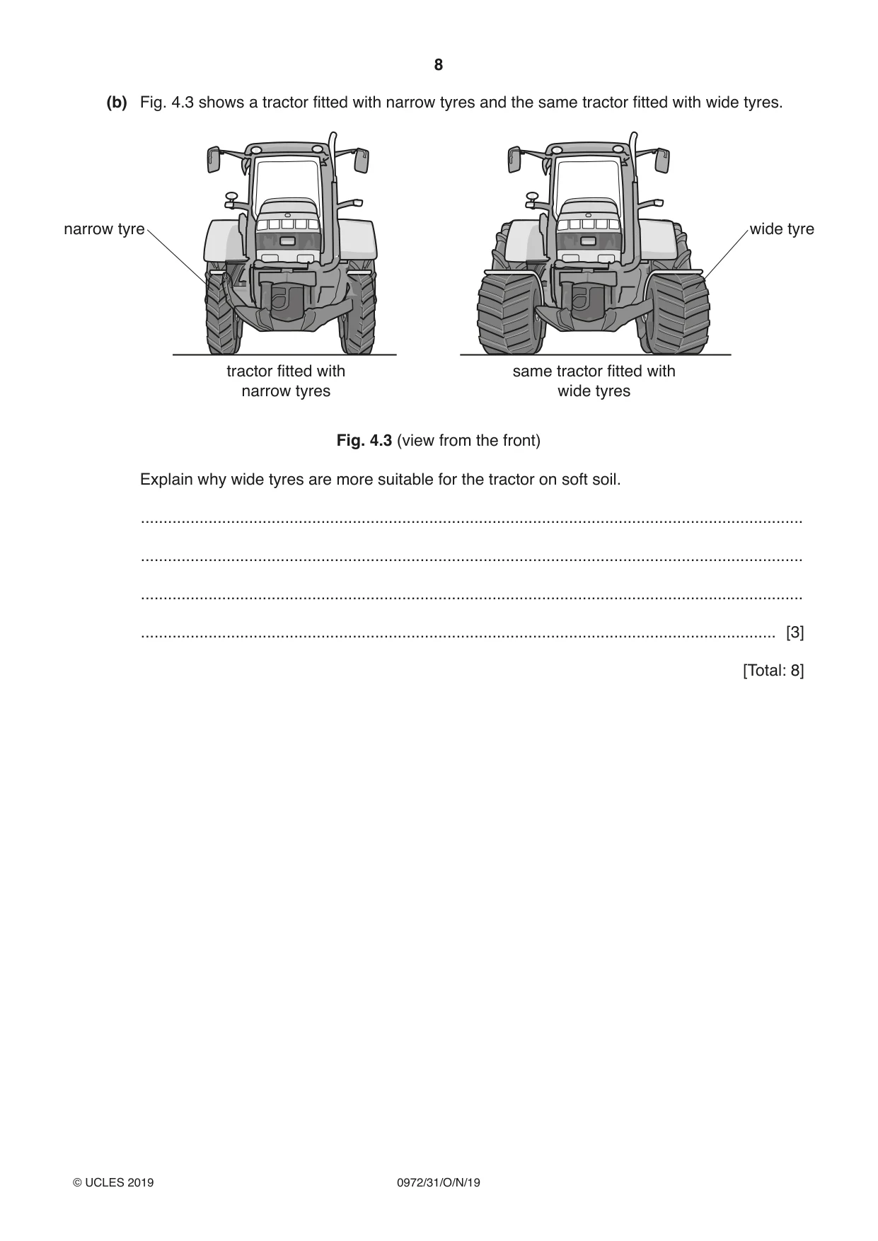
4 Fig. 4.1 shows a tractor fitted with a device for breaking up soil in a field. tractor device heavy weight pivot point soil Fig. 4.1 (a) (i) The tractor has a heavy weight at the front. Explain why the heavy weight is needed. ........................................................................................................................................... ..................................................................................................................................... [1] (ii) Fig. 4.2 represents the weight of the device and its distance from the pivot. pivot 2.1 m 6000 N Fig. 4.2 Calculate the moment of the weight of the device about the pivot. State the unit. moment = ........................................................ [4] (b) Fig. 4.3 shows a tractor fitted with narrow tyres and the same tractor fitted with wide tyres. narrow tyre wide tyre tractor fitted with same tractor fitted with narrow tyres wide tyres Fig. 4.3 (view from the front) Explain why wide tyres are more suitable for the tractor on soft soil. ................................................................................................................................................... ................................................................................................................................................... ................................................................................................................................................... ............................................................................................................................................. [3] [Total: 8]
Mark scheme: 4(a)(i) stop the tractor tipping up/keep tractor level owtte B1 4(a)(ii) moment = force × (perp.) distance from pivot in any form C1 6000 × 2.1 C1 12 600 A1 Nm B1 4(b) Any three from: (wide tyres have) greater area (in contact with ground) pressure = force ÷ area in any form the bigger the area the smaller the pressure so tractor less likely to sink/become stuck (in soft ground) B3
Q5 · Here are some statements about energy and energy resources
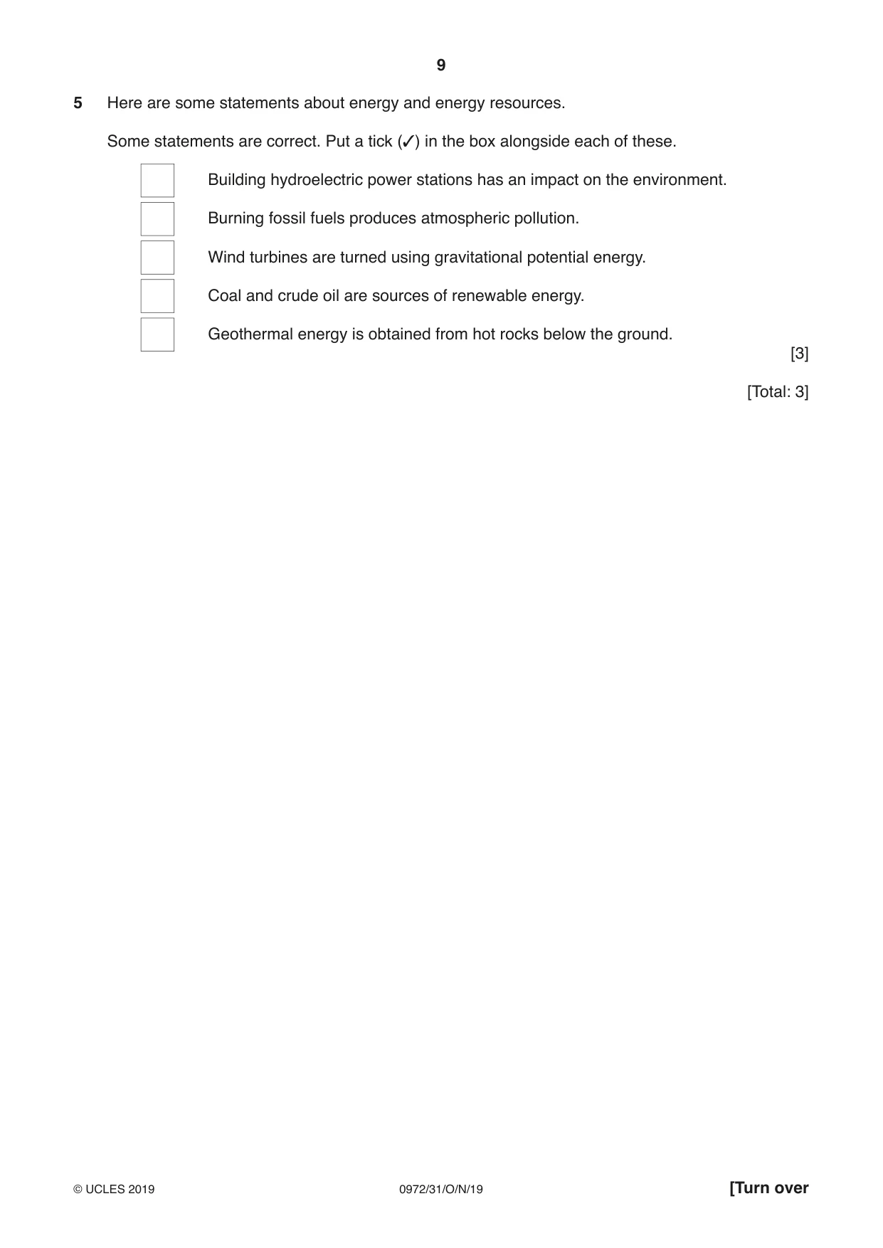
5 Here are some statements about energy and energy resources. Some statements are correct. Put a tick (✓) in the box alongside each of these. Building hydroelectric power stations has an impact on the environment. Burning fossil fuels produces atmospheric pollution. Wind turbines are turned using gravitational potential energy. Coal and crude oil are sources of renewable energy. Geothermal energy is obtained from hot rocks below the ground. [3] [Total: 3]
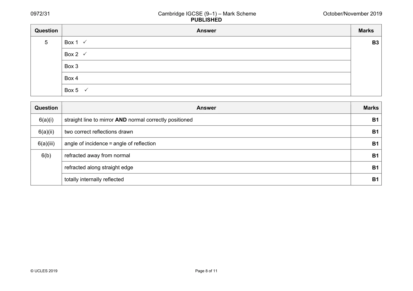
Mark scheme: 5 Box 1 3 B3 Box 2 3 Box 3 Box 4 Box 5 3
Question 6
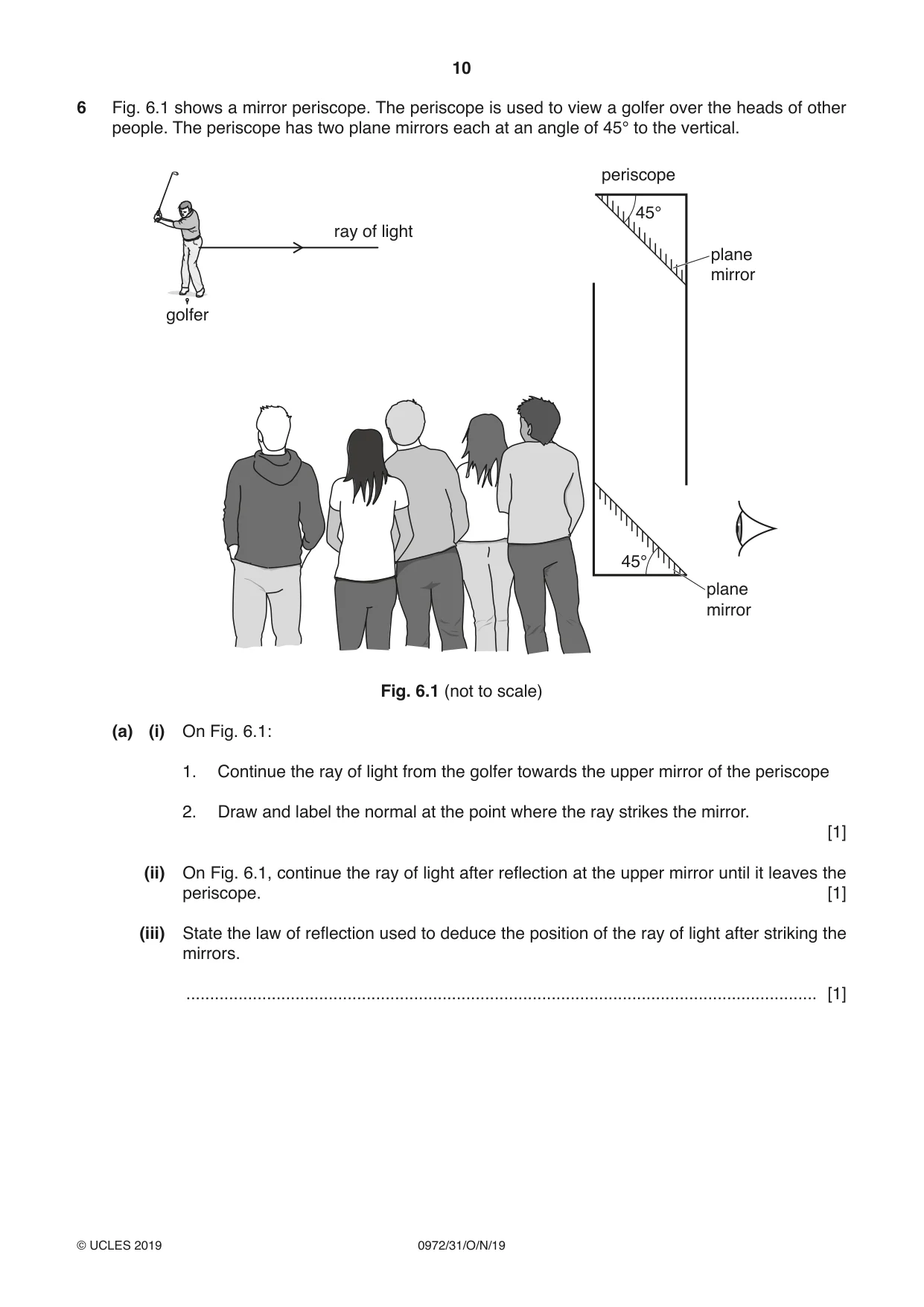
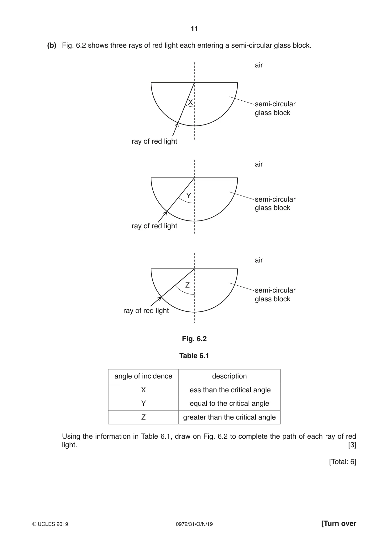
6 Fig. 6.1 shows a mirror periscope. The periscope is used to view a golfer over the heads of other people. The periscope has two plane mirrors each at an angle of 45° to the vertical. periscope 45° ray of light plane mirror golfer 45° plane mirror Fig. 6.1 (not to scale) (a) (i) On Fig. 6.1: 1. Continue the ray of light from the golfer towards the upper mirror of the periscope 2. Draw and label the normal at the point where the ray strikes the mirror. [1] (ii) On Fig. 6.1, continue the ray of light after reflection at the upper mirror until it leaves the periscope. [1] (iii) State the law of reflection used to deduce the position of the ray of light after striking the mirrors. ..................................................................................................................................... [1] (b) Fig. 6.2 shows three rays of red light each entering a semi-circular glass block. air X semi-circular glass block ray of red light air Y semi-circular glass block ray of red light air Z semi-circular glass block ray of red light Fig. 6.2 Table 6.1 angle of incidence description X less than the critical angle Y equal to the critical angle Z greater than the critical angle Using the information in Table 6.1, draw on Fig. 6.2 to complete the path of each ray of red light. [3] [Total: 6]
Mark scheme: 6(a)(i) straight line to mirror AND normal correctly positioned B1 6(a)(ii) two correct reflections drawn B1 6(a)(iii) angle of incidence = angle of reflection B1 6(b) refracted away from normal B1 refracted along straight edge B1 totally internally reflected B1
Q7 · An object, OX, is placed in front of a converging lens
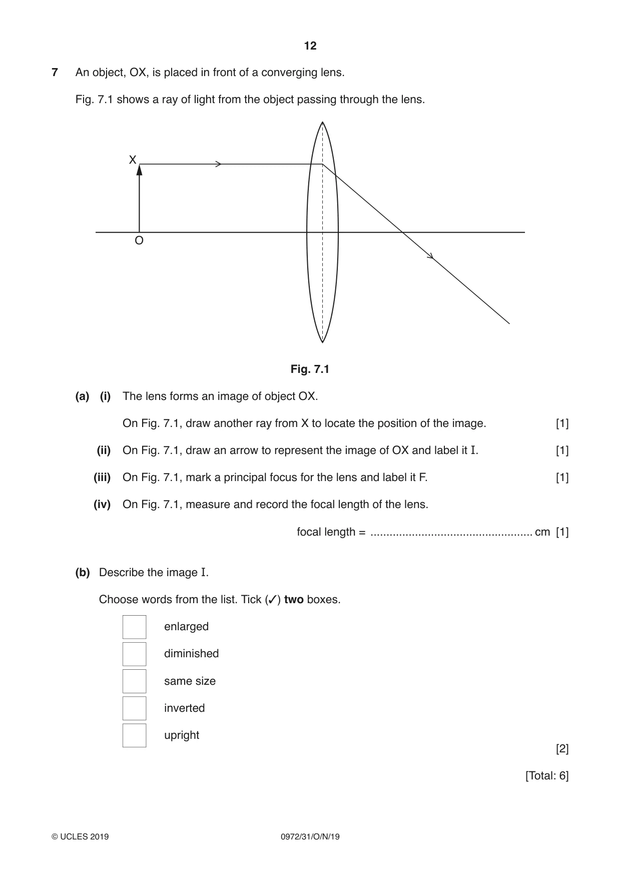
7 An object, OX, is placed in front of a converging lens. Fig. 7.1 shows a ray of light from the object passing through the lens. X O Fig. 7.1 (a) (i) The lens forms an image of object OX. On Fig. 7.1, draw another ray from X to locate the position of the image. [1] (ii) On Fig. 7.1, draw an arrow to represent the image of OX and label it I. [1] (iii) On Fig. 7.1, mark a principal focus for the lens and label it F. [1] (iv) On Fig. 7.1, measure and record the focal length of the lens. focal length = ................................................... cm [1] (b) Describe the image I. Choose words from the list. Tick (✓) two boxes. enlarged diminished same size inverted upright [2] [Total: 6]
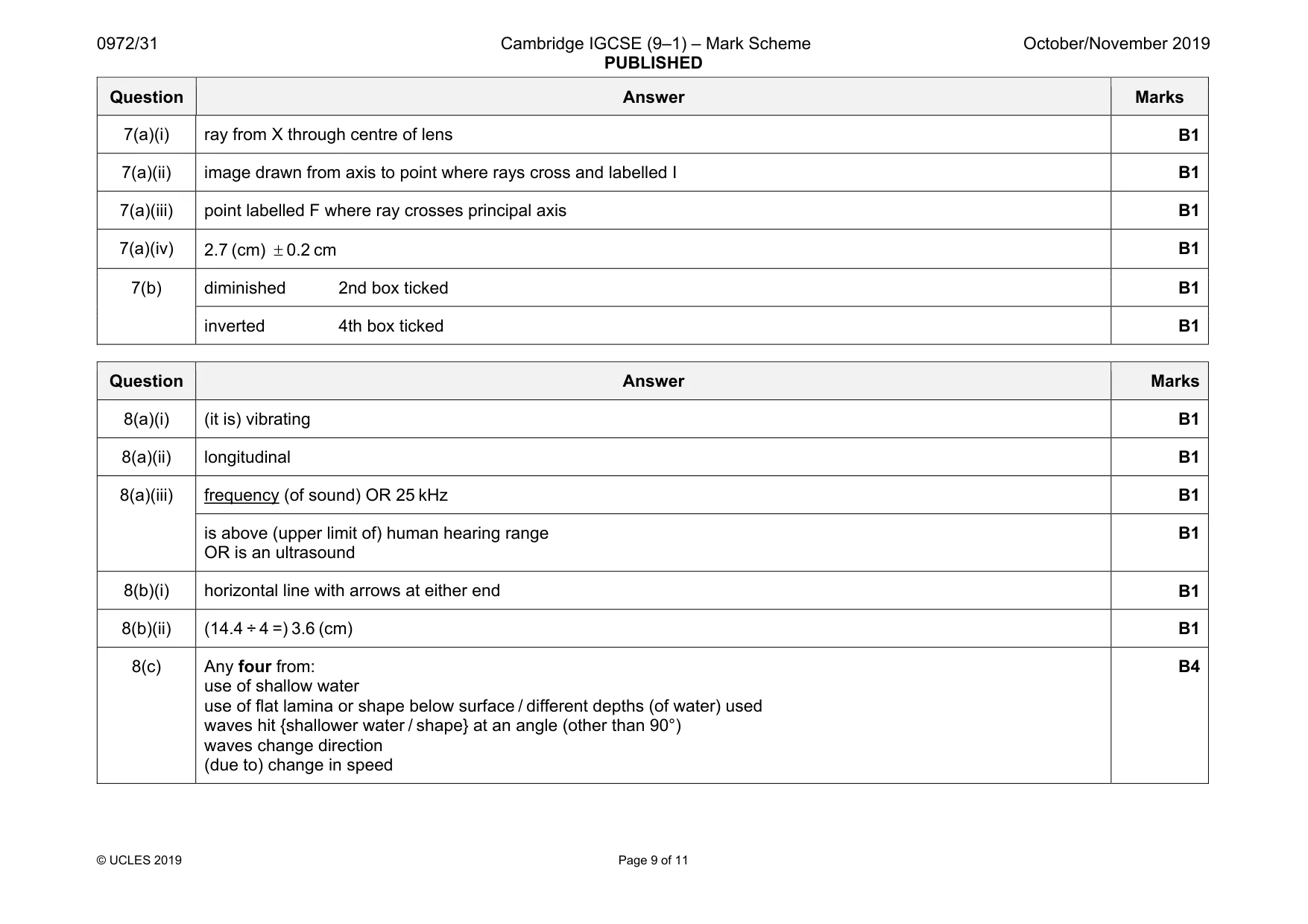
Mark scheme: 7(a)(i) ray from X through centre of lens B1 7(a)(ii) image drawn from axis to point where rays cross and labelled I B1 7(a)(iii) point labelled F where ray crosses principal axis B1 7(a)(iv) 2.7 (cm) ± 0.2 cm B1 7(b) diminished 2nd box ticked B1 inverted 4th box ticked B1
Q8 · A student listening to the sound produced by a tuning fork
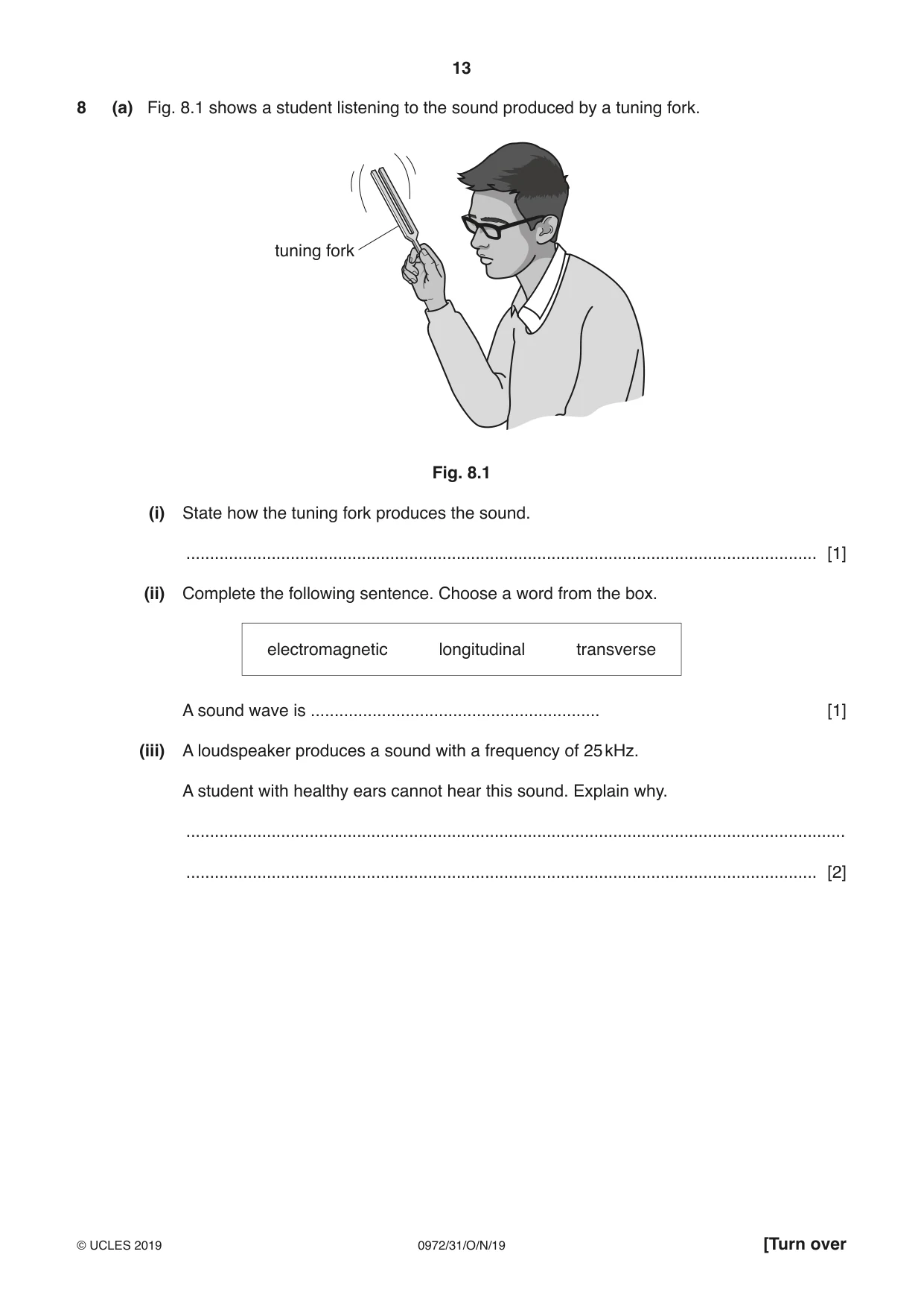
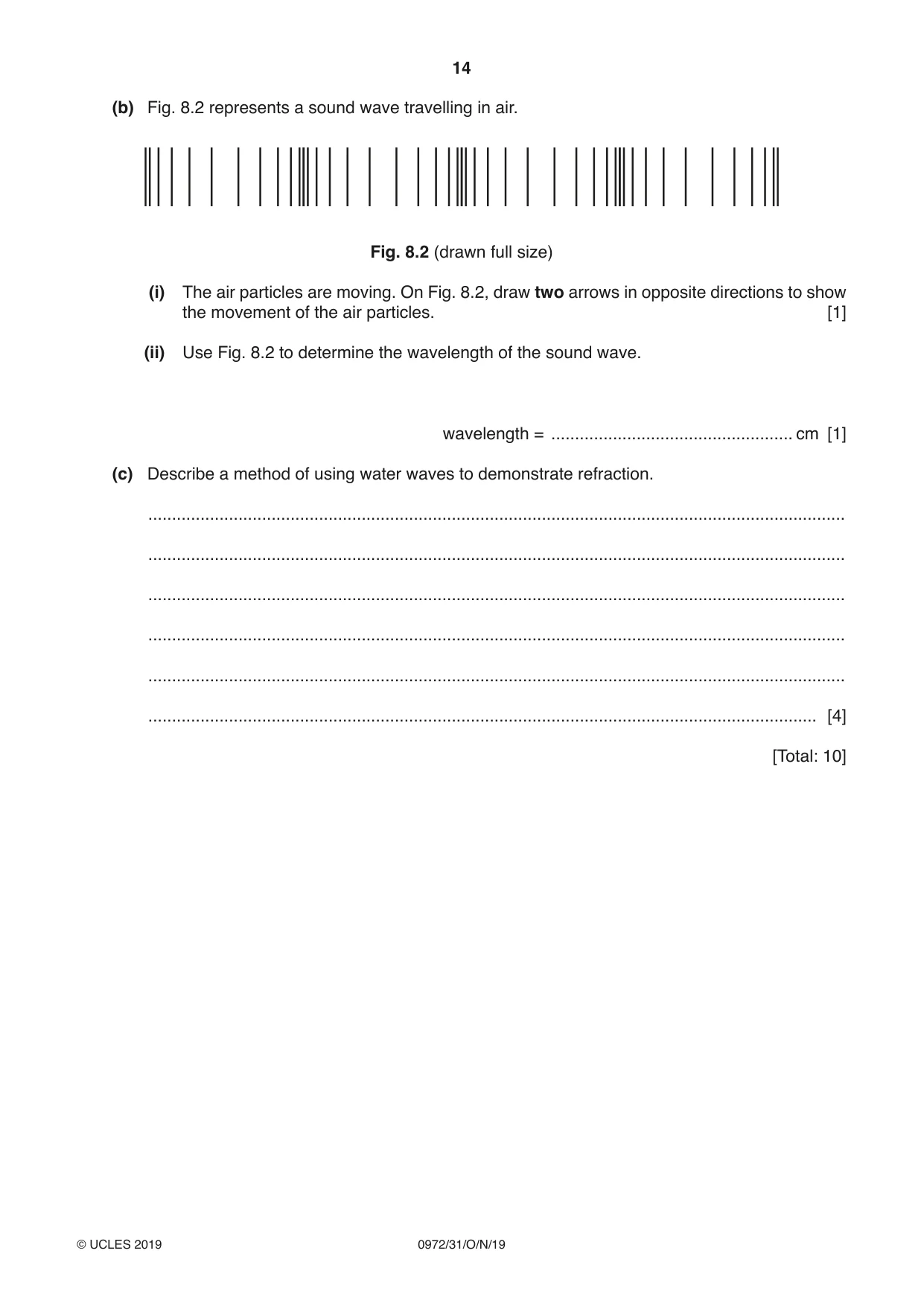
8 (a) Fig. 8.1 shows a student listening to the sound produced by a tuning fork. tuning fork Fig. 8.1 (i) State how the tuning fork produces the sound. ..................................................................................................................................... [1] (ii) Complete the following sentence. Choose a word from the box. electromagnetic longitudinal transverse A sound wave is ............................................................. [1] (iii) A loudspeaker produces a sound with a frequency of 25 kHz. A student with healthy ears cannot hear this sound. Explain why. ........................................................................................................................................... ..................................................................................................................................... [2] (b) Fig. 8.2 represents a sound wave travelling in air. Fig. 8.2 (drawn full size) (i) The air particles are moving. On Fig. 8.2, draw two arrows in opposite directions to show the movement of the air particles. [1] (ii) Use Fig. 8.2 to determine the wavelength of the sound wave. wavelength = ................................................... cm [1] (c) Describe a method of using water waves to demonstrate refraction. ................................................................................................................................................... ................................................................................................................................................... ................................................................................................................................................... ................................................................................................................................................... ................................................................................................................................................... ............................................................................................................................................. [4] [Total: 10]
Mark scheme: 8(a)(i) (it is) vibrating B1 8(a)(ii) longitudinal B1 8(a)(iii) frequency (of sound) OR 25 kHz B1 is above (upper limit of) human hearing range OR is an ultrasound B1 8(b)(i) horizontal line with arrows at either end B1 8(b)(ii) (14.4 ÷ 4 =) 3.6 (cm) B1 8(c) Any four from: use of shallow water use of flat lamina or shape below surface / different depths (of water) used waves hit {shallower water / shape} at an angle (other than 90°) waves change direction (due to) change in speed B4
Q9 · A student is experimenting with magnets and electric charges
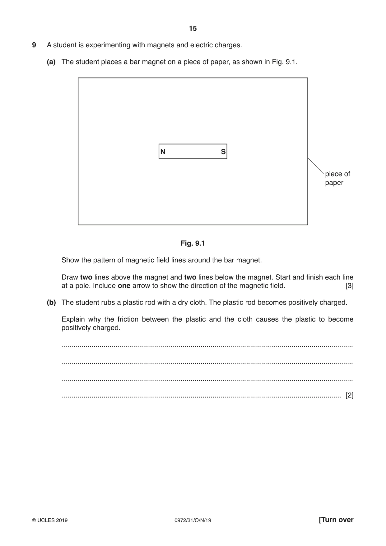
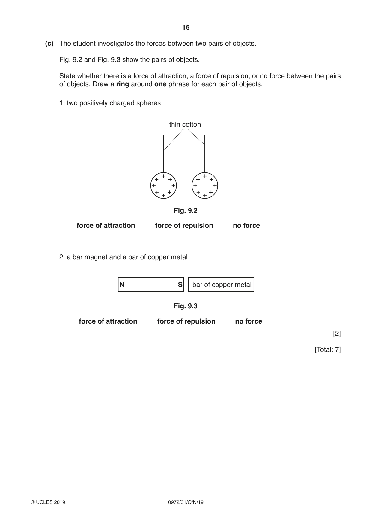
9 A student is experimenting with magnets and electric charges. (a) The student places a bar magnet on a piece of paper, as shown in Fig. 9.1. N S piece of paper Fig. 9.1 Show the pattern of magnetic field lines around the bar magnet. Draw two lines above the magnet and two lines below the magnet. Start and finish each line at a pole. Include one arrow to show the direction of the magnetic field. [3] (b) The student rubs a plastic rod with a dry cloth. The plastic rod becomes positively charged. Explain why the friction between the plastic and the cloth causes the plastic to become positively charged. ................................................................................................................................................... ................................................................................................................................................... ................................................................................................................................................... ............................................................................................................................................. [2] (c) The student investigates the forces between two pairs of objects. Fig. 9.2 and Fig. 9.3 show the pairs of objects. State whether there is a force of attraction, a force of repulsion, or no force between the pairs of objects. Draw a ring around one phrase for each pair of objects. 1. two positively charged spheres thin cotton + + + + + + + + + + + + + + + + Fig. 9.2 force of attraction force of repulsion no force 2. a bar magnet and a bar of copper metal N S bar of copper metal Fig. 9.3 force of attraction force of repulsion no force [2] [Total: 7]
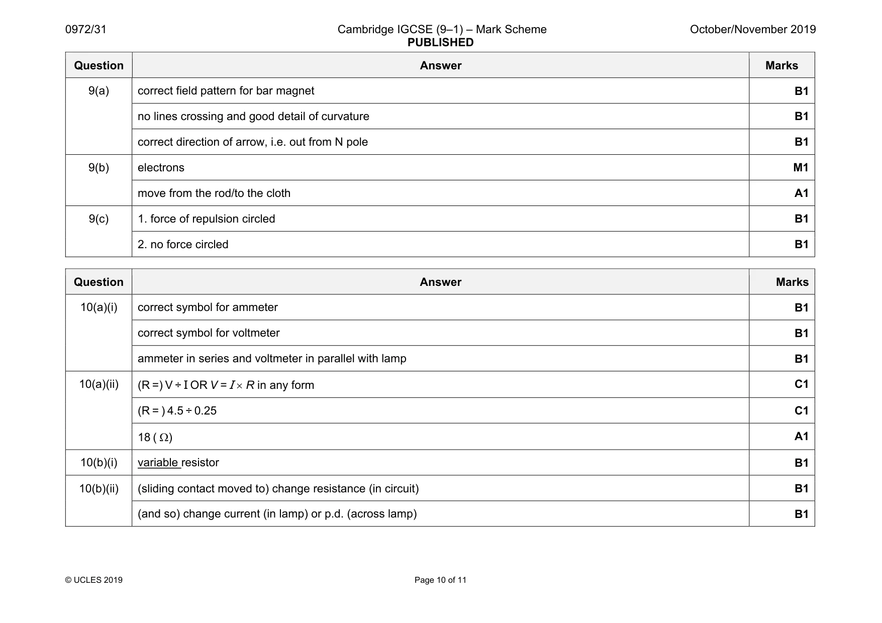
Mark scheme: 9(a) correct field pattern for bar magnet B1 no lines crossing and good detail of curvature B1 correct direction of arrow, i.e. out from N pole B1 9(b) electrons M1 move from the rod/to the cloth A1 9(c) 1. force of repulsion circled B1 2. no force circled B1
Q10 · A teacher is investigating the resistance of a lamp
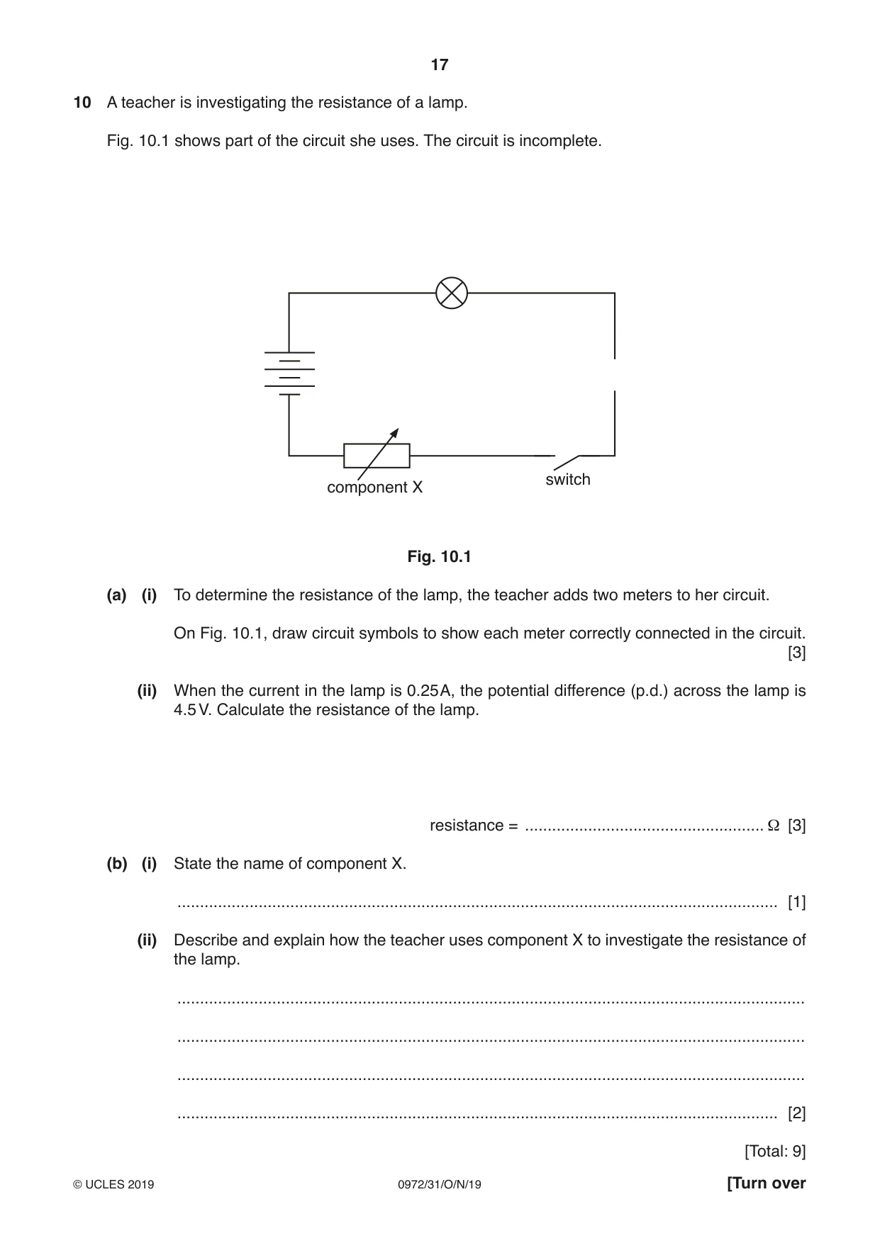
10 A teacher is investigating the resistance of a lamp. Fig. 10.1 shows part of the circuit she uses. The circuit is incomplete. switch component X Fig. 10.1 (a) (i) To determine the resistance of the lamp, the teacher adds two meters to her circuit. On Fig. 10.1, draw circuit symbols to show each meter correctly connected in the circuit. [3] (ii) When the current in the lamp is 0.25 A, the potential difference (p.d.) across the lamp is 4.5 V. Calculate the resistance of the lamp. resistance = ..................................................... Ω [3] (b) (i) State the name of component X. ..................................................................................................................................... [1] (ii) Describe and explain how the teacher uses component X to investigate the resistance of the lamp. ........................................................................................................................................... ........................................................................................................................................... ........................................................................................................................................... ..................................................................................................................................... [2] [Total: 9]
Mark scheme: 10(a)(i) correct symbol for ammeter B1 correct symbol for voltmeter B1 ammeter in series and voltmeter in parallel with lamp B1 10(a)(ii) (R =) V ÷ I OR V = I × R in any form C1 (R = ) 4.5 ÷ 0.25 C1 18 ( Ω) A1 10(b)(i) variable resistor B1 10(b)(ii) (sliding contact moved to) change resistance (in circuit) B1 (and so) change current (in lamp) or p.d. (across lamp) B1
Q11 · A student is experimenting with electromagnetic effects
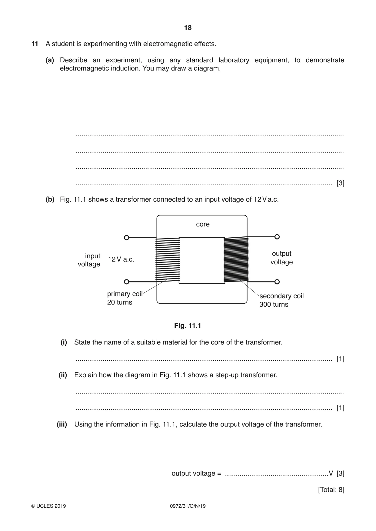
11 A student is experimenting with electromagnetic effects. (a) Describe an experiment, using any standard laboratory equipment, to demonstrate electromagnetic induction. You may draw a diagram. ........................................................................................................................................... ........................................................................................................................................... ........................................................................................................................................... ..................................................................................................................................... [3] (b) Fig. 11.1 shows a transformer connected to an input voltage of 12 V a.c. core output input 12 V a.c. voltage voltage primary coil secondary coil 20 turns 300 turns Fig. 11.1 (i) State the name of a suitable material for the core of the transformer. ..................................................................................................................................... [1] (ii) Explain how the diagram in Fig. 11.1 shows a step-up transformer. ........................................................................................................................................... ..................................................................................................................................... [1] (iii) Using the information in Fig. 11.1, calculate the output voltage of the transformer. output voltage = ......................................................V [3] [Total: 8]
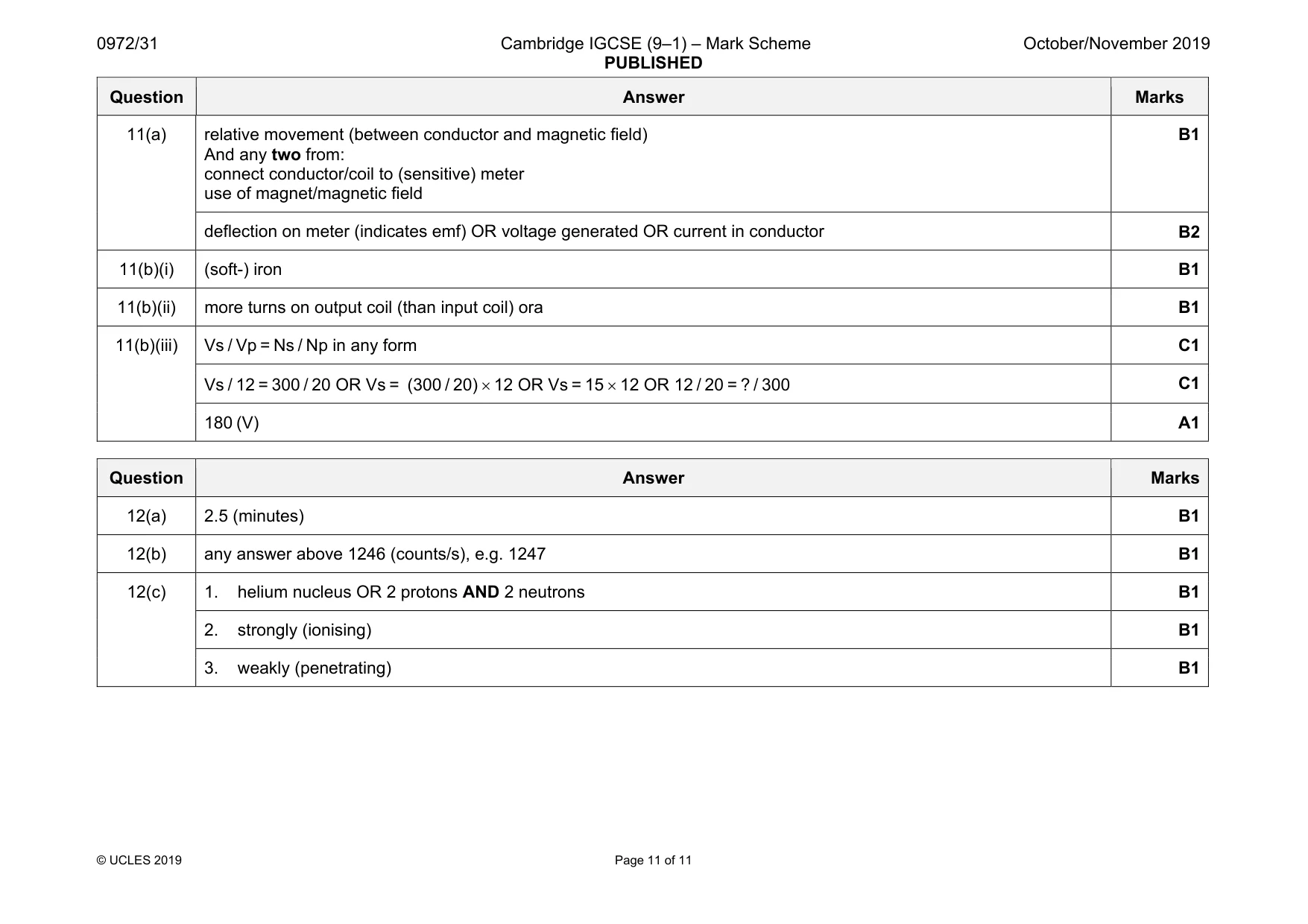
Mark scheme: 11(a) relative movement (between conductor and magnetic field) And any two from: connect conductor/coil to (sensitive) meter use of magnet/magnetic field B1 deflection on meter (indicates emf) OR voltage generated OR current in conductor B2 11(b)(i) (soft-) iron B1 11(b)(ii) more turns on output coil (than input coil) ora B1 11(b)(iii) Vs / Vp = Ns / Np in any form C1 Vs / 12 = 300 / 20 OR Vs = (300 / 20) × 12 OR Vs = 15 × 12 OR 12 / 20 = ? / 300 C1 180 (V) A1
Q12 · A teacher carries out two experiments at the same time
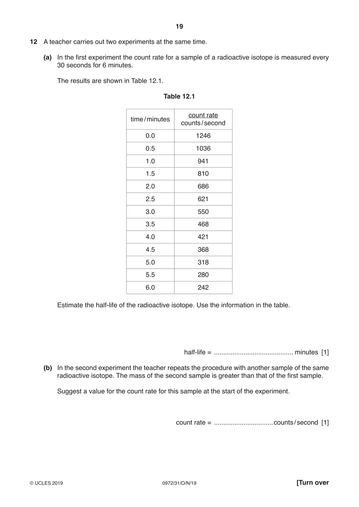
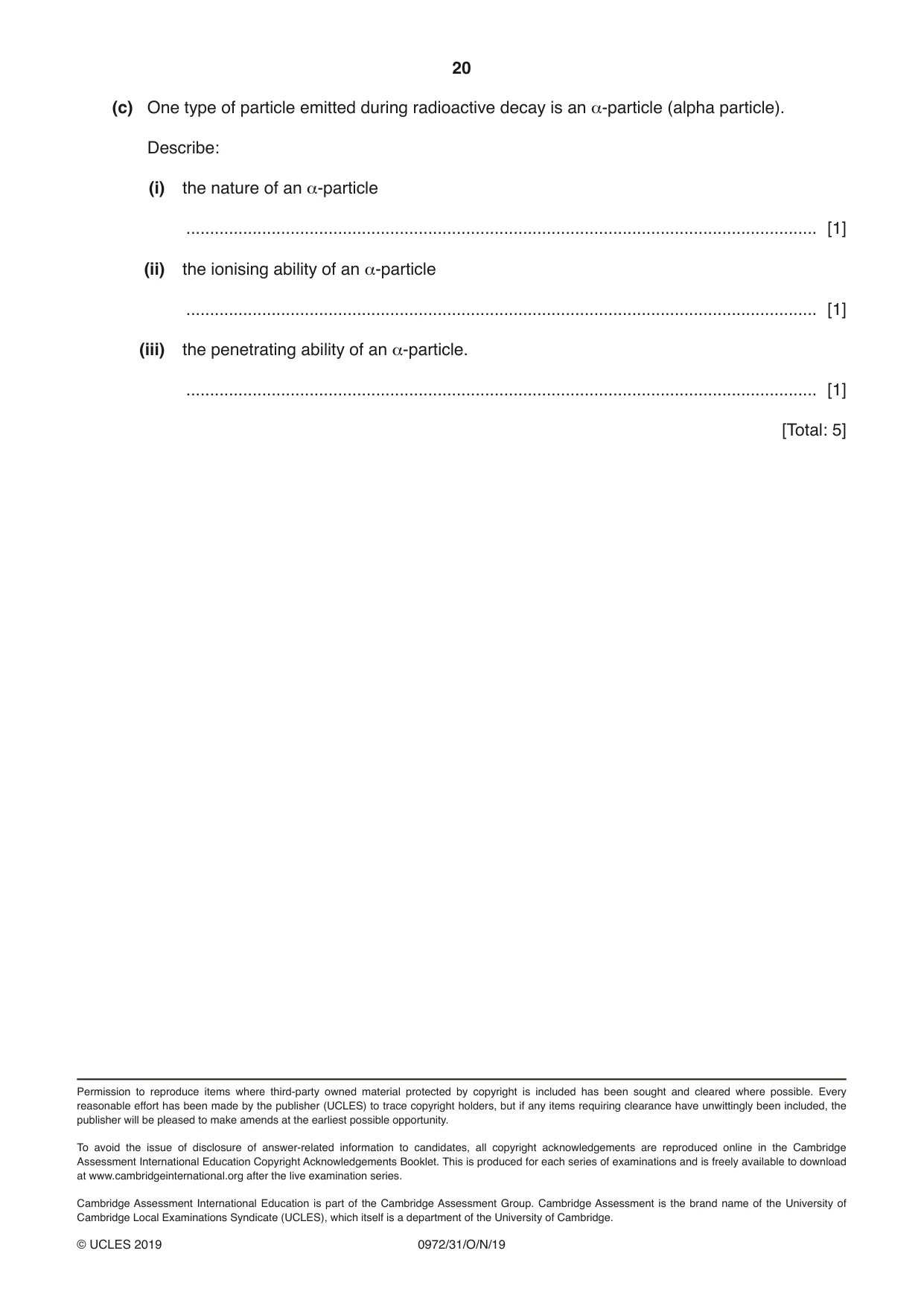
12 A teacher carries out two experiments at the same time. (a) In the first experiment the count rate for a sample of a radioactive isotope is measured every 30 seconds for 6 minutes. The results are shown in Table 12.1. Table 12.1 count rate time / minutes counts / second 0.0 1246 0.5 1036 1.0 941 1.5 810 2.0 686 2.5 621 3.0 550 3.5 468 4.0 421 4.5 368 5.0 318 5.5 280 6.0 242 Estimate the half-life of the radioactive isotope. Use the information in the table. half-life = ........................................... minutes [1] (b) In the second experiment the teacher repeats the procedure with another sample of the same radioactive isotope. The mass of the second sample is greater than that of the first sample. Suggest a value for the count rate for this sample at the start of the experiment. count rate = ................................counts / second [1] (c) One type of particle emitted during radioactive decay is an α-particle (alpha particle). Describe: (i) the nature of an α-particle ..................................................................................................................................... [1] (ii) the ionising ability of an α-particle ..................................................................................................................................... [1] (iii) the penetrating ability of an α-particle. ..................................................................................................................................... [1] [Total: 5]
Mark scheme: 12(a) 2.5 (minutes) B1 12(b) any answer above 1246 (counts/s), e.g. 1247 B1 12(c) 1. helium nucleus OR 2 protons AND 2 neutrons B1 2. strongly (ionising) B1 3. weakly (penetrating) B1
What was in this paper
The subtopics covered by these 12 questions, and how many questions each got. Open one in a new tab to see every Cambridge question on it.
What you needed in this session
Cambridge’s own grade thresholds for 2019 Oct/Nov, Paper 3 · Variant 1. A higher threshold means an easier paper — the bar moves with how the cohort did.