Cambridge IGCSE Physics 0625 — 2013 Oct/Nov Paper 5 · Variant 1
0625/51/O/N/13 · 4 questions · 40 marks · ≈45 min
The question paper and its mark scheme, free to read here and free to download. This is Cambridge’s own paper, exactly as it was sat.
Question paper12 pages



Mark scheme3 pages
Answers below. Sit the paper first if you are practising.
Questions as text
Q1 · In this experiment, you will investigate the stretching of a spring
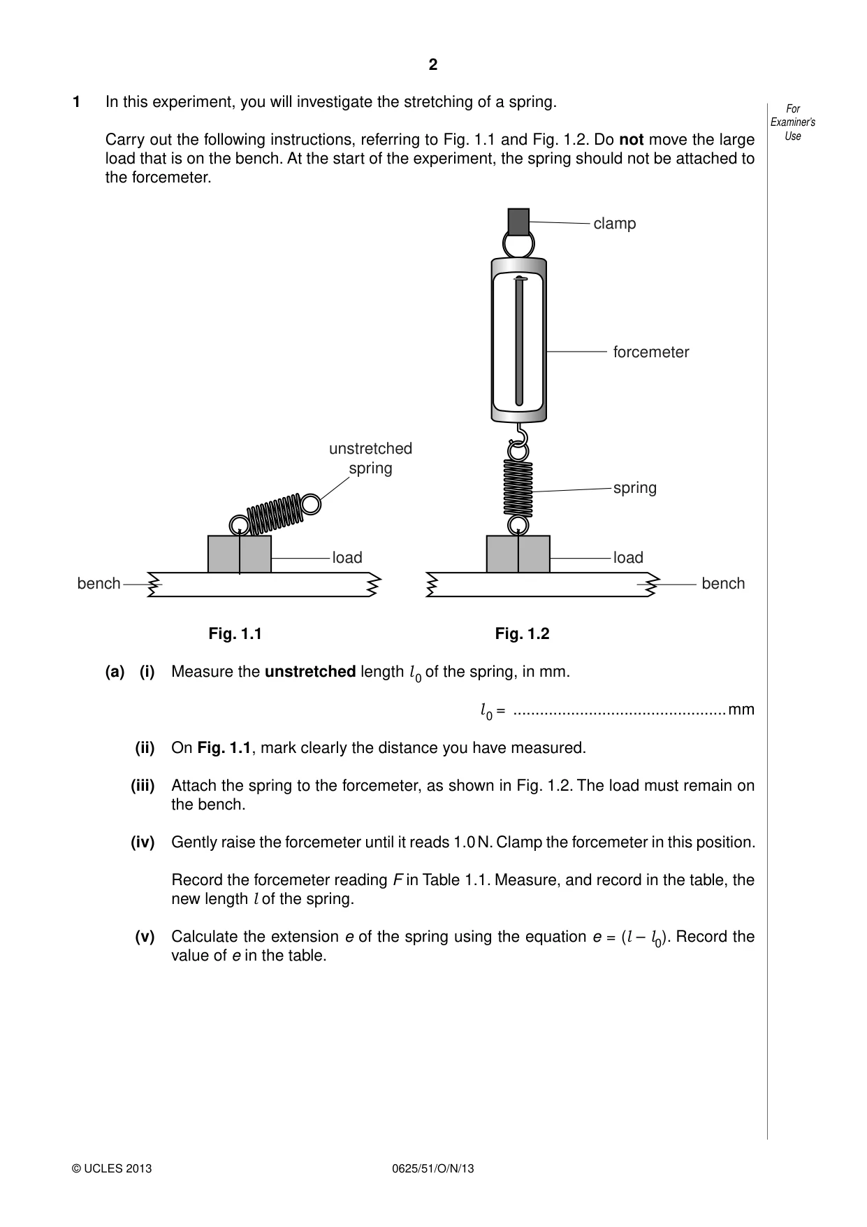
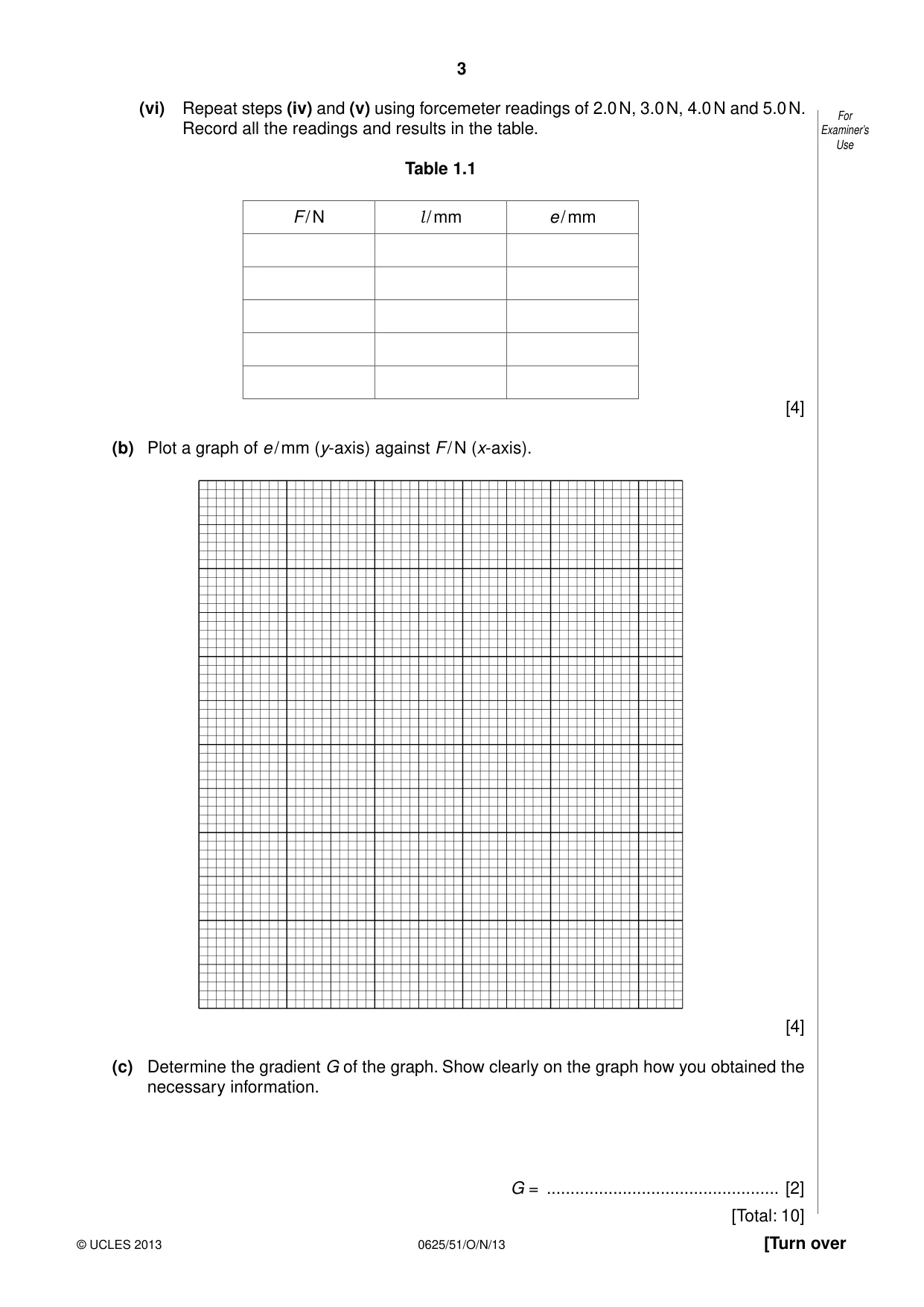
1 In this experiment, you will investigate the stretching of a spring. For Examiner’s Carry out the following instructions, referring to Fig. 1.1 and Fig. 1.2. Do not move the large Use load that is on the bench. At the start of the experiment, the spring should not be attached to the forcemeter. clamp forcemeter unstretched spring spring load load bench bench Fig. 1.1 Fig. 1.2 (a) (i) Measure the unstretched length l of the spring, in mm. 0 l = ................................................mm 0 (ii) On Fig. 1.1, mark clearly the distance you have measured. (iii) Attach the spring to the forcemeter, as shown in Fig. 1.2. The load must remain on the bench. (iv) Gently raise the forcemeter until it reads 1.0 N. Clamp the forcemeter in this position. Record the forcemeter reading F in Table 1.1. Measure, and record in the table, the new length l of the spring. (v) Calculate the extension e of the spring using the equation e = (l – l0). Record the value of e in the table. (vi) Repeat steps (iv) and (v) using forcemeter readings of 2.0 N, 3.0 N, 4.0 N and 5.0 N. For Record all the readings and results in the table. Examiner’s Use Table 1.1 F / N l / mm e / mm [4] (b) Plot a graph of e / mm (y-axis) against F / N (x-axis). [4] (c) Determine the gradient G of the graph. Show clearly on the graph how you obtained the necessary information. G = ................................................. [2] [Total: 10]
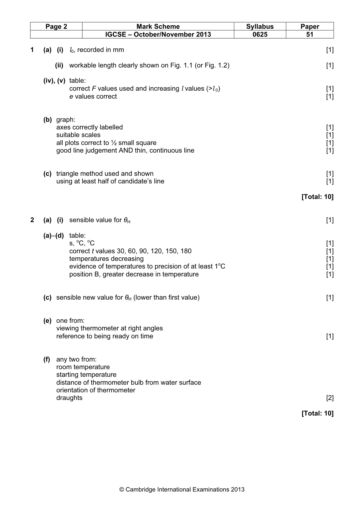
Mark scheme: 1 (a) (i) l0, recorded in mm [1] (ii) workable length clearly shown on Fig. 1.1 (or Fig. 1.2) [1] (iv), (v) table: correct F values used and increasing l values (>l 0) [1] e values correct [1] (b) graph: axes correctly labelled [1] suitable scales [1] all plots correct to ½ small square [1] good line judgement AND thin, continuous line [1] (c) triangle method used and shown [1] using at least half of candidate’s line [1] [Total: 10]
More questions on Physical quantities and measurement techniques
Q2 · In this experiment, you will investigate the cooling of a thermometer bulb
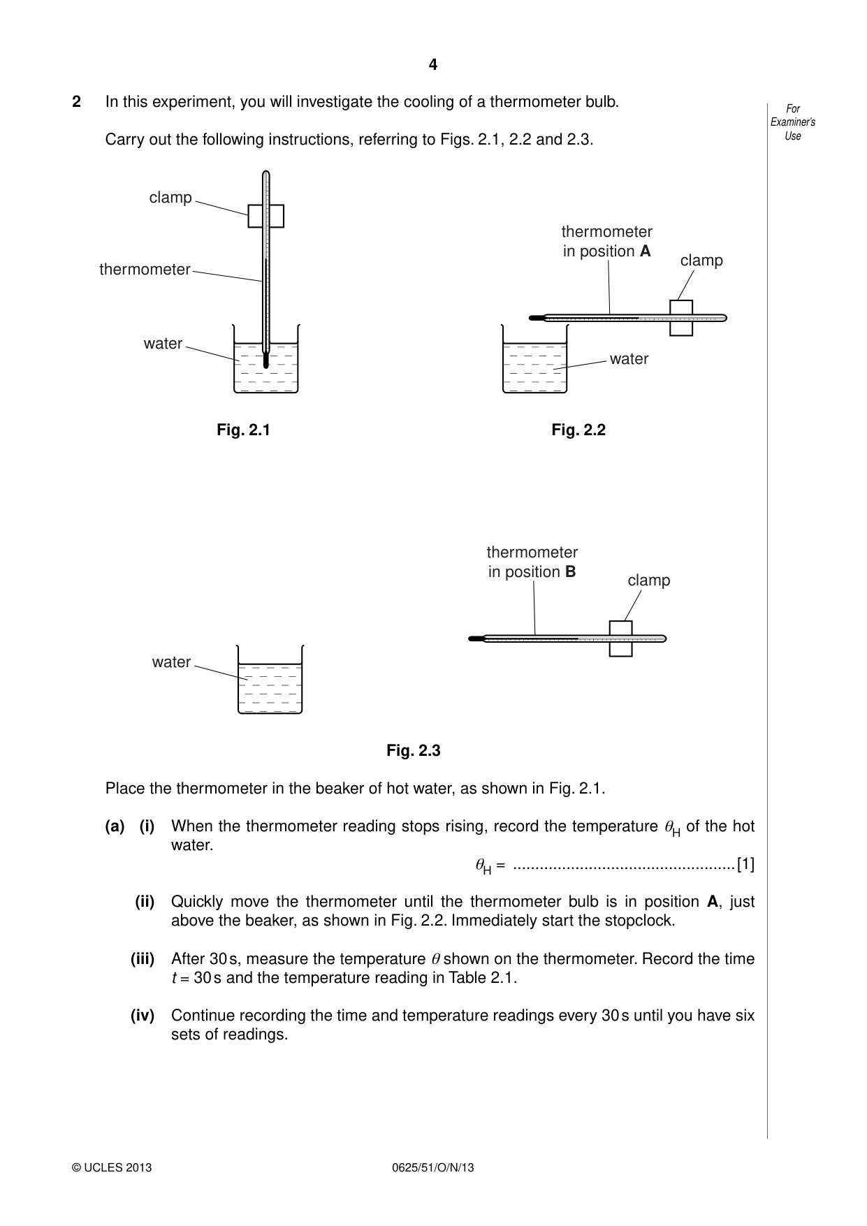
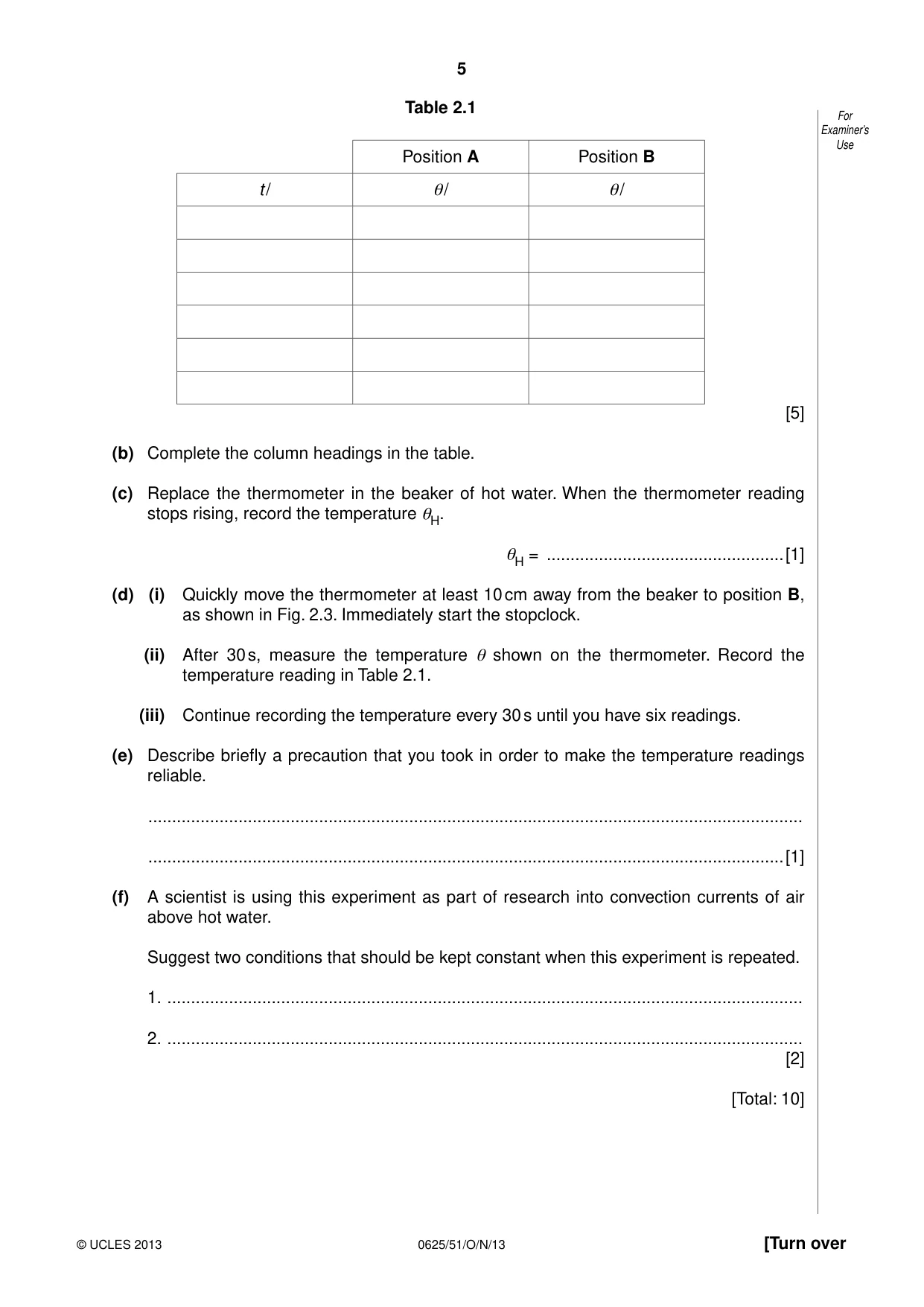
2 In this experiment, you will investigate the cooling of a thermometer bulb. For Examiner’s Carry out the following instructions, referring to Figs. 2.1, 2.2 and 2.3. Use clamp thermometer in position A clamp thermometer water water Fig. 2.1 Fig. 2.2 thermometer in position B clamp water Fig. 2.3 Place the thermometer in the beaker of hot water, as shown in Fig. 2.1. (a) (i) When the thermometer reading stops rising, record the temperature θH of the hot water. θH = ..................................................[1] (ii) Quickly move the thermometer until the thermometer bulb is in position A, just above the beaker, as shown in Fig. 2.2. Immediately start the stopclock. (iii) After 30 s, measure the temperature θ shown on the thermometer. Record the time t = 30 s and the temperature reading in Table 2.1. (iv) Continue recording the time and temperature readings every 30 s until you have six sets of readings. Table 2.1 For Examiner’s Use Position A Position B t / θ/ θ/ [5] (b) Complete the column headings in the table. (c) Replace the thermometer in the beaker of hot water. When the thermometer reading stops rising, record the temperature θH. θH = ..................................................[1] (d) (i) Quickly move the thermometer at least 10 cm away from the beaker to position B, as shown in Fig. 2.3. Immediately start the stopclock. (ii) After 30 s, measure the temperature θ shown on the thermometer. Record the temperature reading in Table 2.1. (iii) Continue recording the temperature every 30 s until you have six readings. (e) Describe briefly a precaution that you took in order to make the temperature readings reliable. .......................................................................................................................................... ......................................................................................................................................[1] (f) A scientist is using this experiment as part of research into convection currents of air above hot water. Suggest two conditions that should be kept constant when this experiment is repeated. 1. ...................................................................................................................................... 2. ...................................................................................................................................... [2] [Total: 10]
Mark scheme: 2 (a) (i) sensible value for θH [1] (a)–(d) table: s, oC, oC [1] correct t values 30, 60, 90, 120, 150, 180 [1] temperatures decreasing [1] evidence of temperatures to precision of at least 1oC [1] position B, greater decrease in temperature [1] (c) sensible new value for θH (lower than first value) [1] (e) one from: viewing thermometer at right angles reference to being ready on time [1] (f) any two from: room temperature starting temperature distance of thermometer bulb from water surface orientation of thermometer draughts [2] [Total: 10] IGCSE – October/November 2013 0625 51
Q3 · In this experiment, you will investigate the power of lamps in a circuit
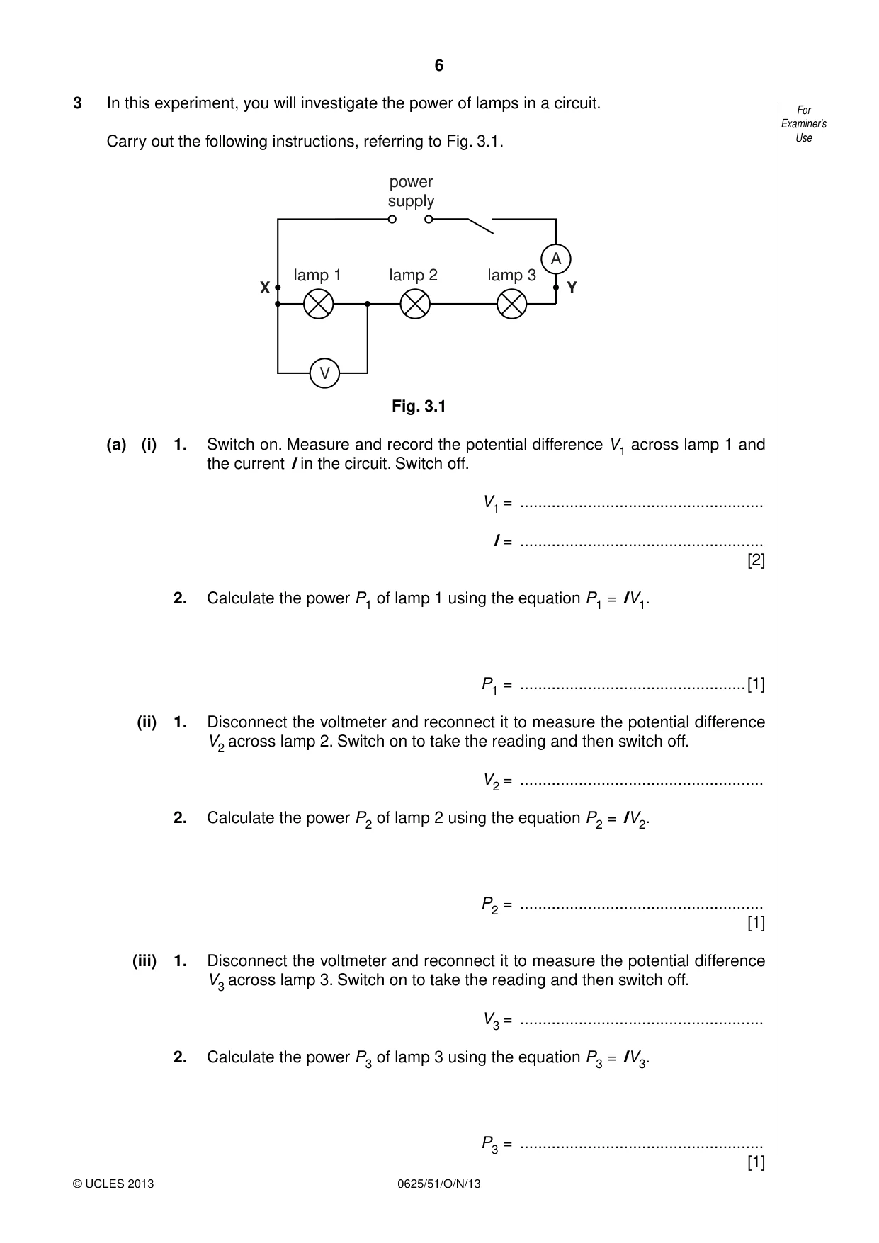
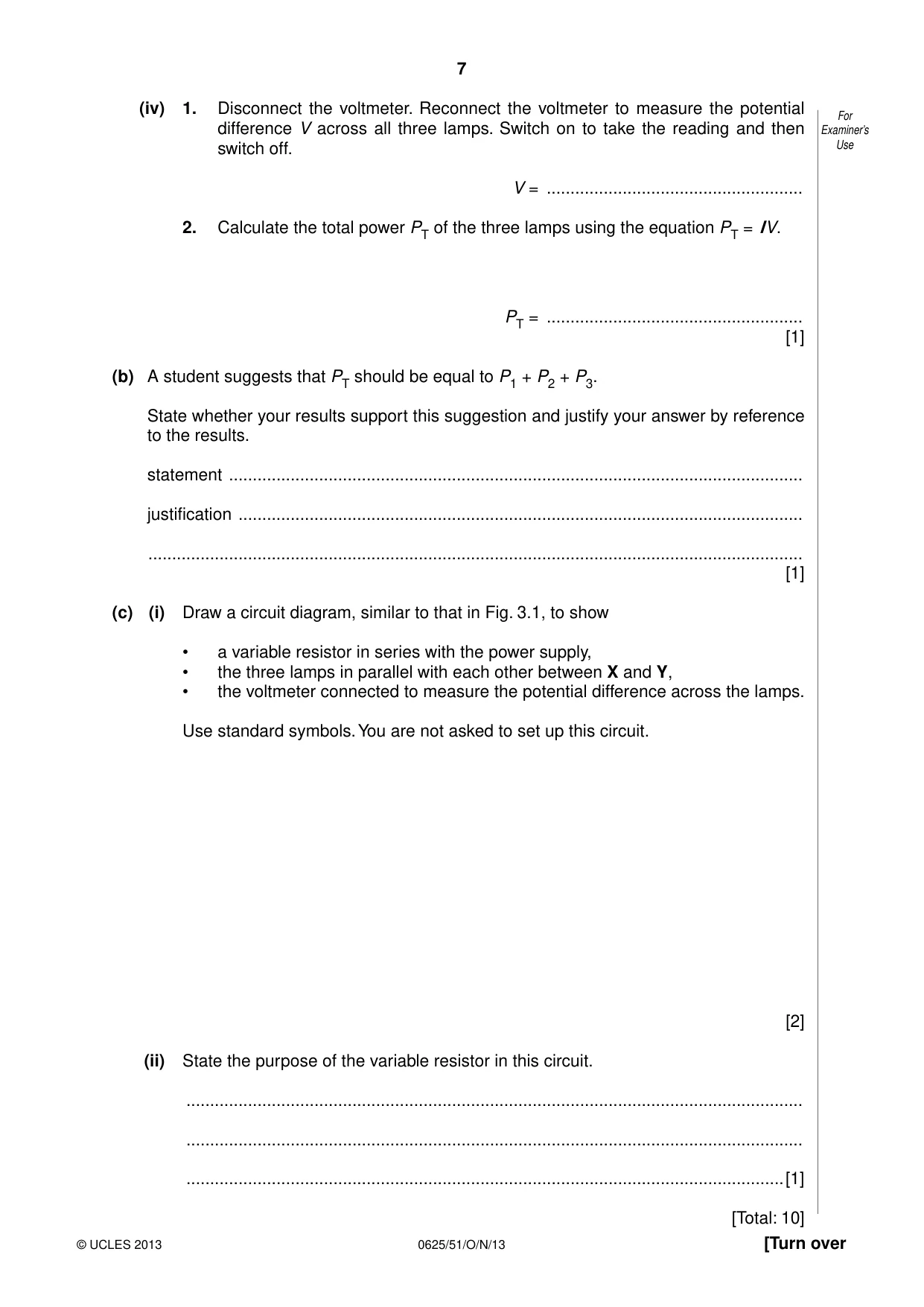
3 In this experiment, you will investigate the power of lamps in a circuit. For Examiner’s Carry out the following instructions, referring to Fig. 3.1. Use power supply A lamp 1 lamp 2 lamp 3 X Y V Fig. 3.1 (a) (i) 1. Switch on. Measure and record the potential difference V1 across lamp 1 and the current I in the circuit. Switch off. V1 = ...................................................... I = ...................................................... [2] 2. Calculate the power P1 of lamp 1 using the equation P1 = IV1. P1 = ..................................................[1] (ii) 1. Disconnect the voltmeter and reconnect it to measure the potential difference V2 across lamp 2. Switch on to take the reading and then switch off. V2 = ...................................................... 2. Calculate the power P2 of lamp 2 using the equation P2 = IV2. P2 = ...................................................... [1] (iii) 1. Disconnect the voltmeter and reconnect it to measure the potential difference V3 across lamp 3. Switch on to take the reading and then switch off. V3 = ...................................................... 2. Calculate the power P3 of lamp 3 using the equation P3 = IV3. P3 = ...................................................... [1] (iv) 1. Disconnect the voltmeter. Reconnect the voltmeter to measure the potential For difference V across all three lamps. Switch on to take the reading and then Examiner’s switch off. Use V = ...................................................... 2. Calculate the total power PT of the three lamps using the equation PT = IV. PT = ...................................................... [1] (b) A student suggests that PT should be equal to P1 + P2 + P3. State whether your results support this suggestion and justify your answer by reference to the results. statement ......................................................................................................................... justification ....................................................................................................................... .......................................................................................................................................... [1] (c) (i) Draw a circuit diagram, similar to that in Fig. 3.1, to show • a variable resistor in series with the power supply, • the three lamps in parallel with each other between X and Y, • the voltmeter connected to measure the potential difference across the lamps. Use standard symbols. You are not asked to set up this circuit. [2] (ii) State the purpose of the variable resistor in this circuit. .................................................................................................................................. .................................................................................................................................. ..............................................................................................................................[1] [Total: 10]
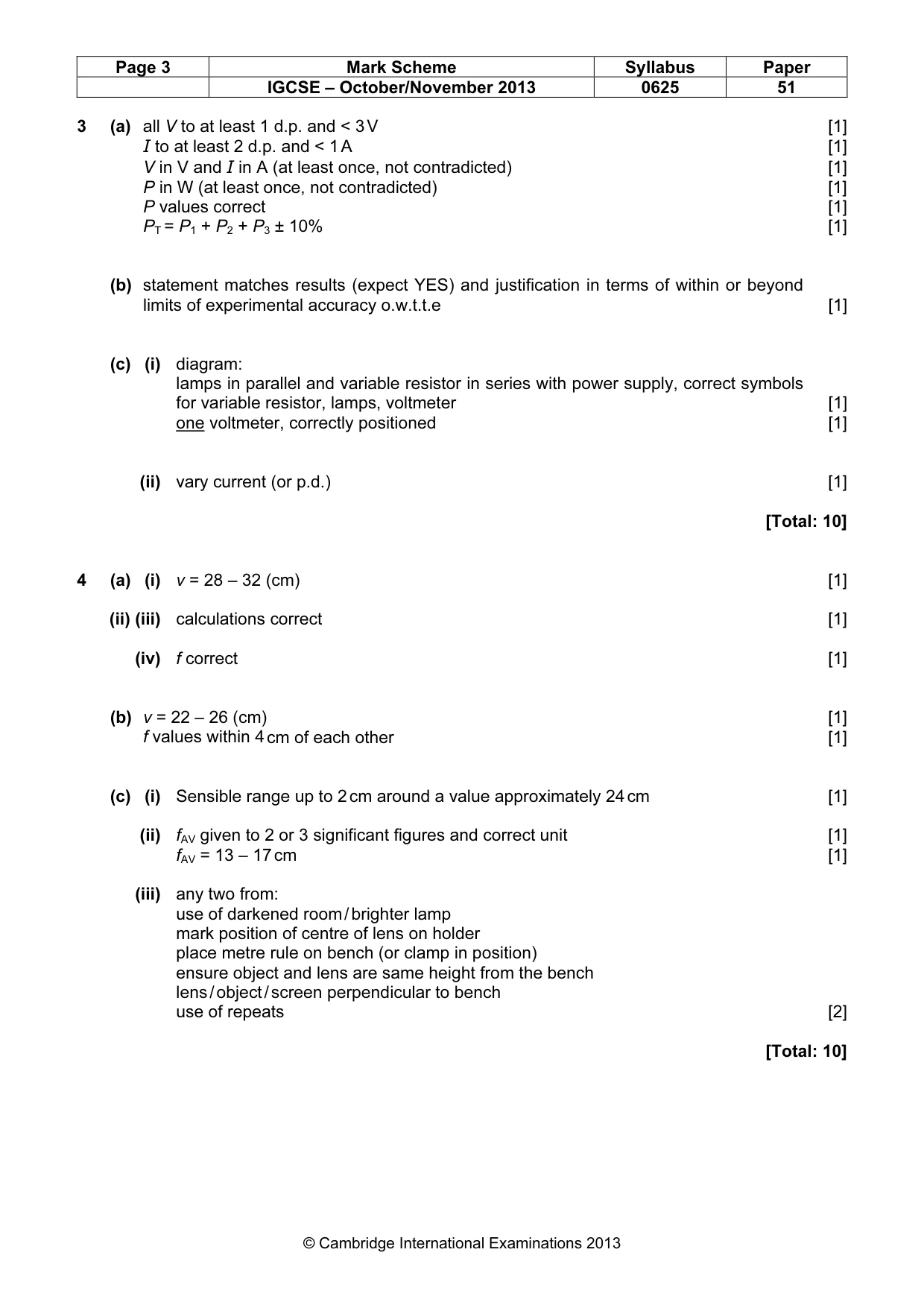
Mark scheme: 3 (a) all V to at least 1 d.p. and < 3 V [1] I to at least 2 d.p. and < 1 A [1] V in V and I in A (at least once, not contradicted) [1] P in W (at least once, not contradicted) [1] P values correct [1] PT = P1 + P2 + P3 ± 10% [1] (b) statement matches results (expect YES) and justification in terms of within or beyond limits of experimental accuracy o.w.t.t.e [1] (c) (i) diagram: lamps in parallel and variable resistor in series with power supply, correct symbols for variable resistor, lamps, voltmeter [1] one voltmeter, correctly positioned [1] (ii) vary current (or p.d.) [1] [Total: 10]
Q4 · In this experiment, you will determine the focal length of a converging lens
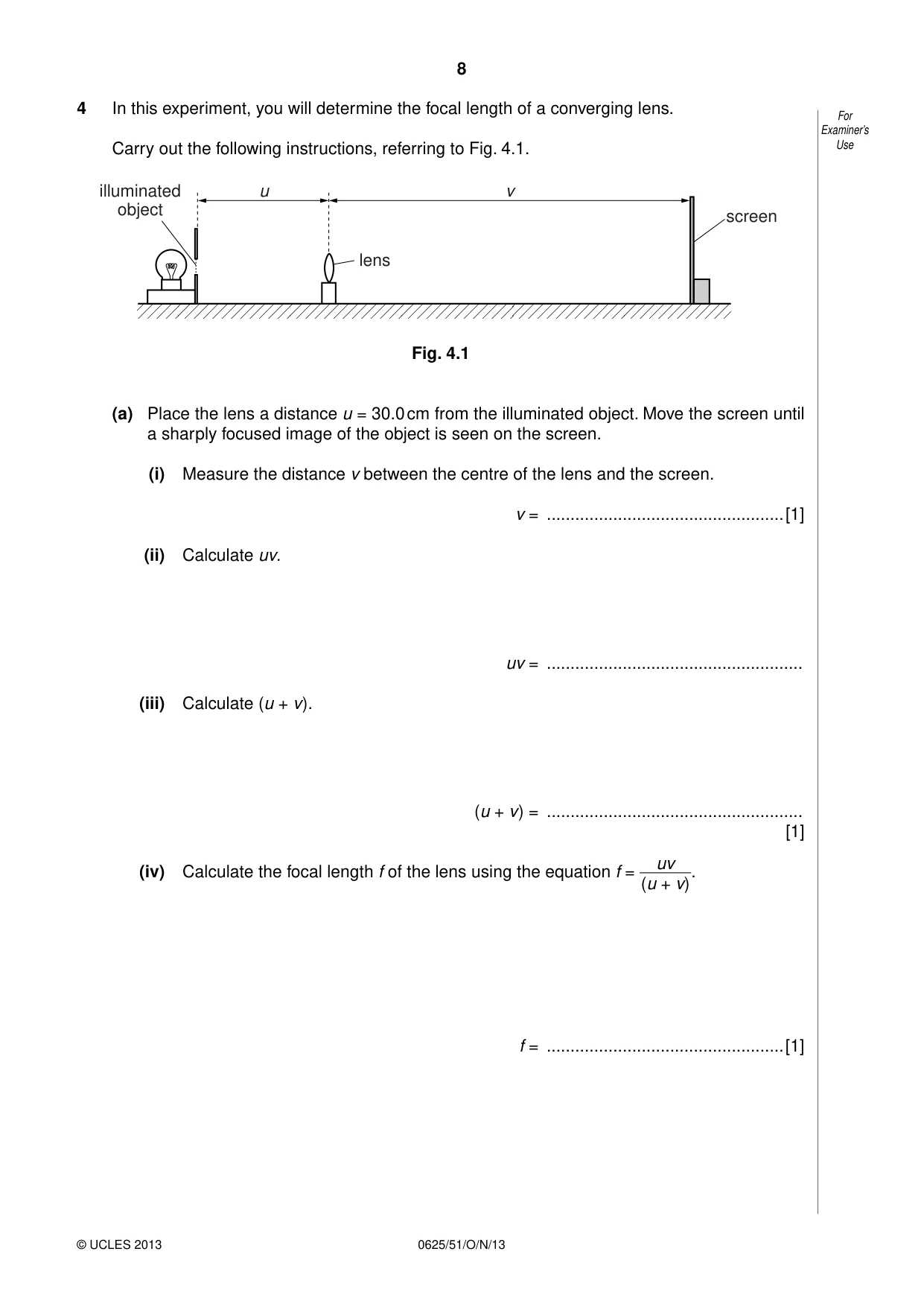
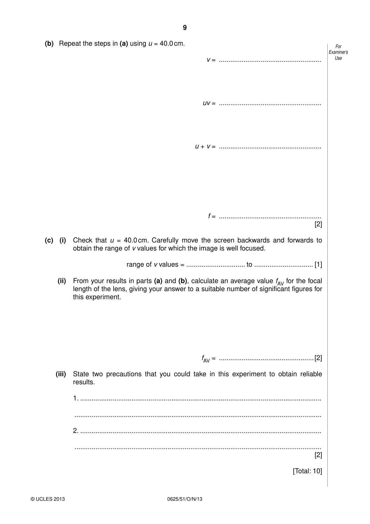
4 In this experiment, you will determine the focal length of a converging lens. For Examiner’s Carry out the following instructions, referring to Fig. 4.1. Use illuminated u v object screen lens Fig. 4.1 (a) Place the lens a distance u = 30.0 cm from the illuminated object. Move the screen until a sharply focused image of the object is seen on the screen. (i) Measure the distance v between the centre of the lens and the screen. v = ..................................................[1] (ii) Calculate uv. uv = ...................................................... (iii) Calculate (u + v ). (u + v ) = ...................................................... [1] uv (iv) Calculate the focal length f of the lens using the equation f = (u + v). f = ..................................................[1] (b) Repeat the steps in (a) using u = 40.0 cm. For Examiner’s v = ...................................................... Use uv = ...................................................... u + v = ...................................................... f = ...................................................... [2] (c) (i) Check that u = 40.0 cm. Carefully move the screen backwards and forwards to obtain the range of v values for which the image is well focused. range of v values = ............................... to ............................... [1] (ii) From your results in parts (a) and (b), calculate an average value fAV for the focal length of the lens, giving your answer to a suitable number of significant figures for this experiment. fAV = ..................................................[2] (iii) State two precautions that you could take in this experiment to obtain reliable results. 1. ............................................................................................................................... .................................................................................................................................. 2. ............................................................................................................................... .................................................................................................................................. [2] [Total: 10]
Mark scheme: 4 (a) (i) v = 28 – 32 (cm) [1] (ii) (iii) calculations correct [1] (iv) f correct [1] (b) v = 22 – 26 (cm) [1] f values within 4 cm of each other [1] (c) (i) Sensible range up to 2 cm around a value approximately 24 cm [1] (ii) fAV given to 2 or 3 significant figures and correct unit [1] fAV = 13 – 17 cm [1] (iii) any two from: use of darkened room / brighter lamp mark position of centre of lens on holder place metre rule on bench (or clamp in position) ensure object and lens are same height from the bench lens / object / screen perpendicular to bench use of repeats [2] [Total: 10]
What was in this paper
The subtopics covered by these 4 questions, and how many questions each got. Open one in a new tab to see every Cambridge question on it.