Cambridge IGCSE Design and Technology 0445 — 2006 May/June Paper 2 · Variant 1
0445/21/M/J/06 · 100 marks · ≈113 min
The question paper and its mark scheme, free to read here and free to download. This is Cambridge’s own paper, exactly as it was sat.
Question paper2 pages
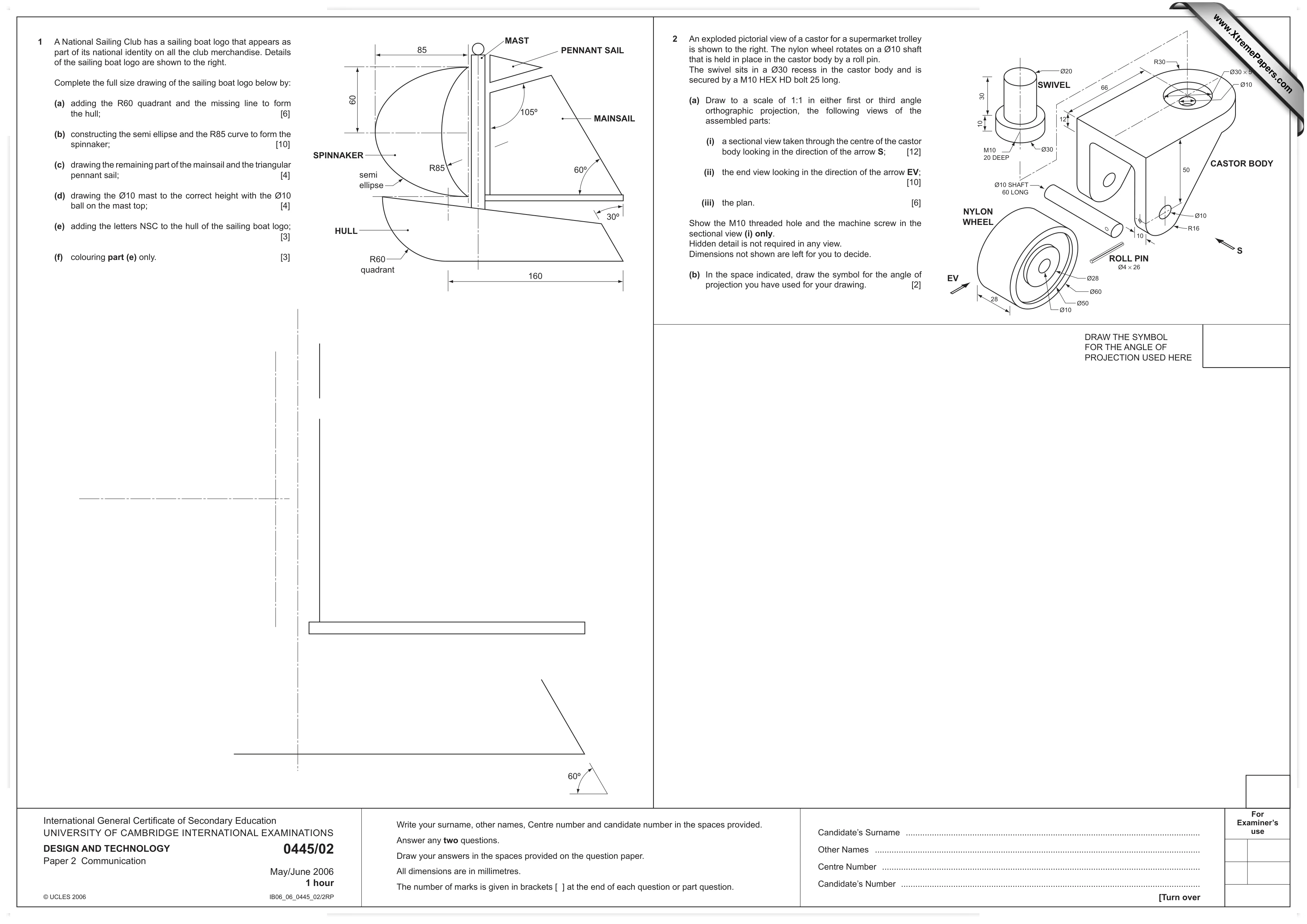
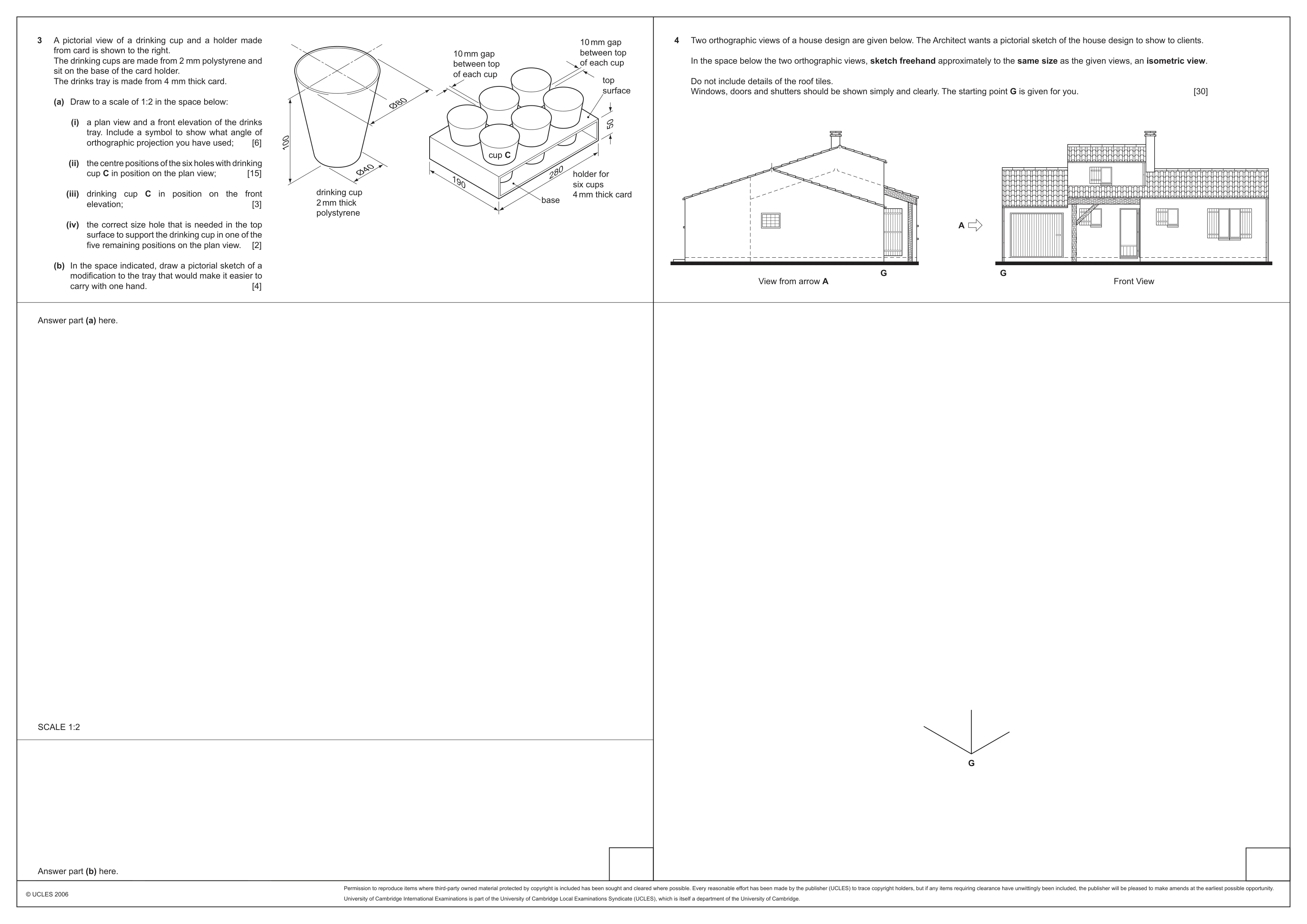
Mark scheme3 pages
Answers below. Sit the paper first if you are practising.
Paper as text
Question paper, page 1
[Turn over International General Certificate of Secondary Education UNIVERSITY OF CAMBRIDGE INTERNATIONAL EXAMINATIONS DESIGN AND TECHNOLOGY Paper 2 Communication © UCLES 2006 0445/02 May/June 2006 1 hour IB06_06_0445_02/2RP For Examiner’s use Candidate’s Surname … Other Names … Centre Number … Candidate’s Number … Write your surname, other names, Centre number and candidate number in the spaces provided. Answer any two questions. Draw your answers in the spaces provided on the question paper. All dimensions are in millimetres. The number of marks is given in brackets [ ] at the end of each question or part question. 30º 60º 105º 60 85 semi ellipse R85 R60 quadrant 160 MAST PENNANT SAIL MAINSAIL HULL SPINNAKER 60º 30 10 M10 20 DEEP Ø30 Ø10 SHAFT 60 LONG Ø20 SWIVEL Ø4 × 26 Ø28 Ø60 Ø50 Ø10 28 EV S NYLON WHEEL 10 Ø10 Ø10 Ø30 × 5 DEEP R16 CASTOR BODY 12 66 R30 50 ROLL PIN 2 An exploded pictorial view of a castor for a supermarket trolley is shown to the right. The nylon wheel rotates on a Ø10 shaft that is held in place in the castor body by a roll pin. The swivel sits in a Ø30 recess in the castor body and is secured by a M10 HEX HD bolt 25 long. (a) Draw to a scale of 1:1 in either first or third angle orthographic projection, the following views of the assembled parts: (i) a sectional view taken through the centre of the castor body looking in the direction of the arrow S; [12] (ii) the end view looking in the direction of the arrow EV; [10] (iii) the plan. [6] Show the M10 threaded hole and the machine screw in the sectional view (i) only. Hidden detail is not required in any view. Dimensions not shown are left for you to decide. (b) In the space indicated, draw the symbol for the angle of projection you have used for your drawing. [2] DRAW THE SYMBOL FOR THE ANGLE OF PROJECTION USED HERE 1 A National Sailing Club has a sailing boat logo that appears as part of its national identity on all the club merchandise. Details of the sailing boat logo are shown to the right. Complete the full size drawing of the sailing boat logo below by: (a) adding the R60 quadrant and the missing line to form the hull; [6] (b) constructing the semi ellipse and the R85 curve to form the spinnaker; [10] (c) drawing the remaining part of the mainsail and the triangular pennant sail; [4] (d) drawing the Ø10 mast to the correct height with the Ø10 ball on the mast top; [4] (e) adding the letters NSC to the hull of the sailing boat logo; [3] (f) colouring part (e) only. [3] www.XtremePapers.com
Question paper, page 2
Permission to reproduce items where third-party owned material protected by copyright is included has been sought and cleared where possible. Every reasonable effort has been made by the publisher (UCLES) to trace copyright holders, but if any items requiring clearance have unwittingly been included, the publisher will be pleased to make amends at the earliest possible opportunity. University of Cambridge International Examinations is part of the University of Cambridge Local Examinations Syndicate (UCLES), which is itself a department of the University of Cambridge. © UCLES 2006 3 A pictorial view of a drinking cup and a holder made from card is shown to the right. The drinking cups are made from 2 mm polystyrene and sit on the base of the card holder. The drinks tray is made from 4 mm thick card. (a) Draw to a scale of 1:2 in the space below: (i) a plan view and a front elevation of the drinks tray. Include a symbol to show what angle of orthographic projection you have used; [6] (ii) the centre positions of the six holes with drinking cup C in position on the plan view; [15] (iii) drinking cup C in position on the front elevation; [3] (iv) the correct size hole that is needed in the top surface to support the drinking cup in one of the five remaining positions on the plan view. [2] (b) In the space indicated, draw a pictorial sketch of a modification to the tray that would make it easier to carry with one hand. [4] 100 50 Ø80 Ø40 drinking cup 2 mm thick polystyrene 190 10 mm gap between top of each cup 10 mm gap between top of each cup top surface 280 base holder for six cups 4 mm thick card cup C Answer part (a) here. SCALE 1:2 Answer part (b) here. 4 Two orthographic views of a house design are given below. The Architect wants a pictorial sketch of the house design to show to clients. In the space below the two orthographic views, sketch freehand approximately to the same size as the given views, an isometric view. Do not include details of the roof tiles. Windows, doors and shutters should be shown simply and clearly. The starting point G is given for you. [30] View from arrow A G Front View G A G
Mark scheme, page 1
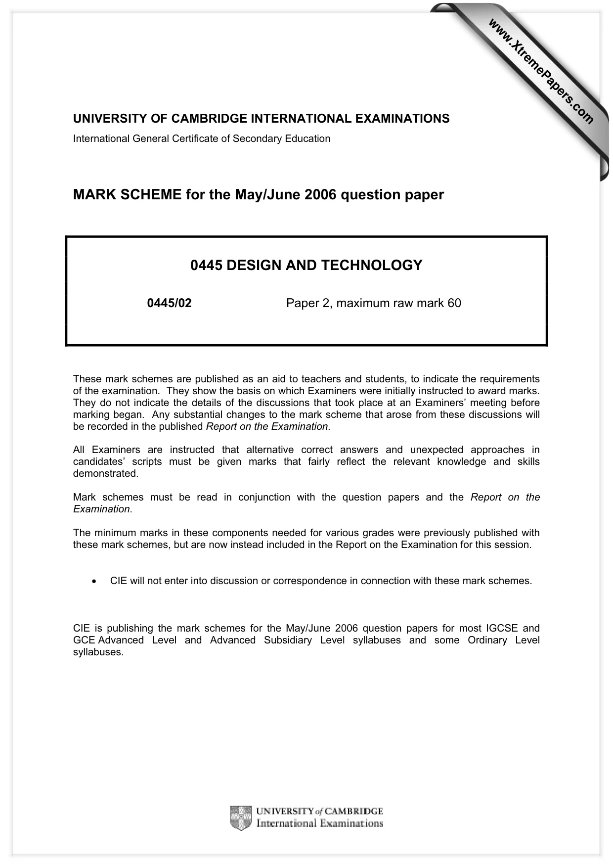
UNIVERSITY OF CAMBRIDGE INTERNATIONAL EXAMINATIONS International General Certificate of Secondary Education MARK SCHEME for the May/June 2006 question paper 0445 DESIGN AND TECHNOLOGY 0445/02 Paper 2, maximum raw mark 60 These mark schemes are published as an aid to teachers and students, to indicate the requirements of the examination. They show the basis on which Examiners were initially instructed to award marks. They do not indicate the details of the discussions that took place at an Examiners’ meeting before marking began. Any substantial changes to the mark scheme that arose from these discussions will be recorded in the published Report on the Examination. All Examiners are instructed that alternative correct answers and unexpected approaches in candidates’ scripts must be given marks that fairly reflect the relevant knowledge and skills demonstrated. Mark schemes must be read in conjunction with the question papers and the Report on the Examination. The minimum marks in these components needed for various grades were previously published with these mark schemes, but are now instead included in the Report on the Examination for this session. • CIE will not enter into discussion or correspondence in connection with these mark schemes. CIE is publishing the mark schemes for the May/June 2006 question papers for most IGCSE and GCE Advanced Level and Advanced Subsidiary Level syllabuses and some Ordinary Level syllabuses. www.XtremePapers.com
Mark scheme, page 2
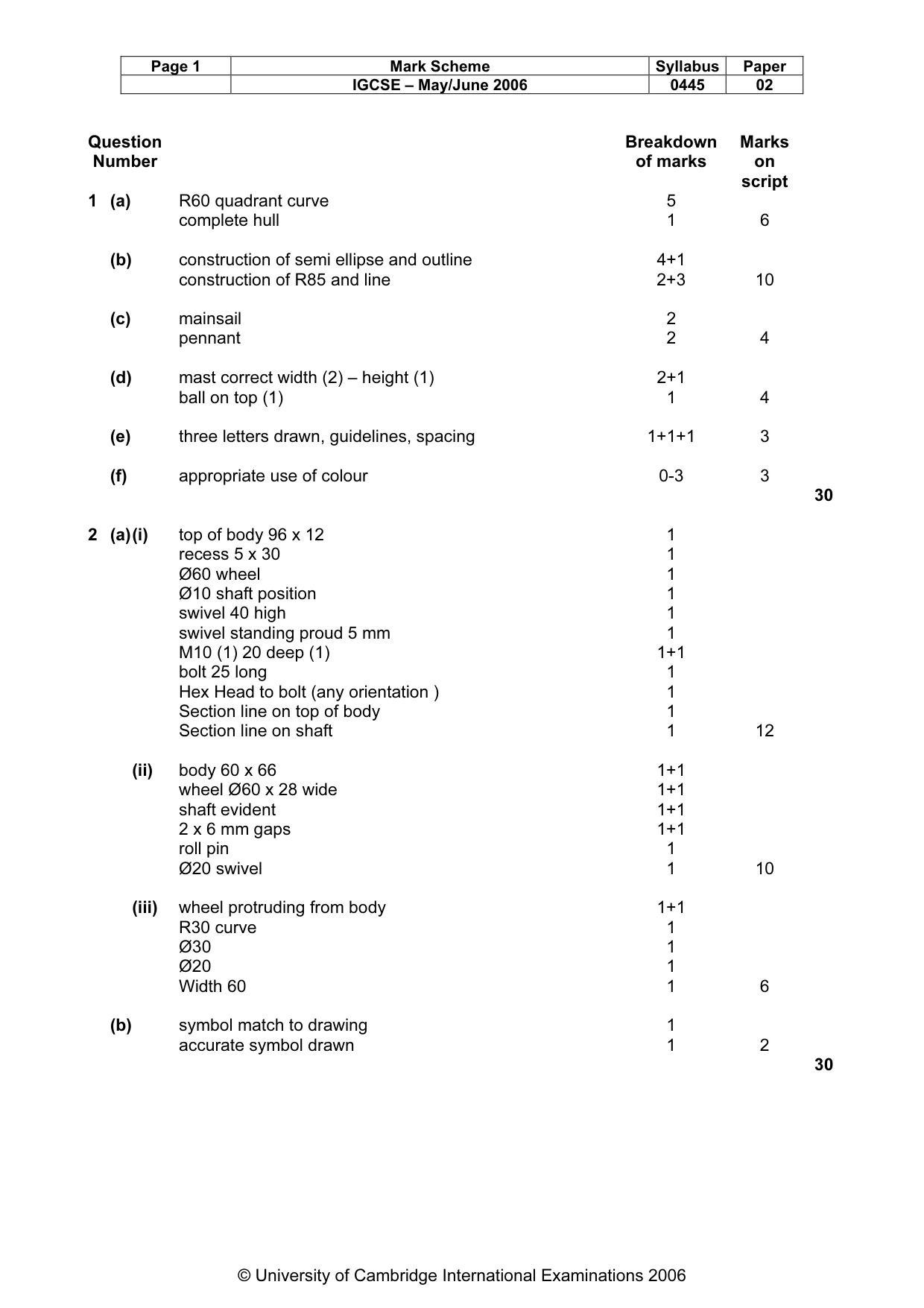
Page 1 Mark Scheme Syllabus Paper IGCSE – May/June 2006 0445 02 © University of Cambridge International Examinations 2006 Question Number Breakdown of marks Marks on script 1 (a) R60 quadrant curve 5 complete hull 1 6 (b) construction of semi ellipse and outline 4+1 construction of R85 and line 2+3 10 (c) mainsail 2 pennant 2 4 (d) mast correct width (2) – height (1) 2+1 ball on top (1) 1 4 (e) three letters drawn, guidelines, spacing 1+1+1 3 (f) appropriate use of colour 0-3 3 30 2 (a) (i) top of body 96 x 12 recess 5 x 30 Ø60 wheel Ø10 shaft position swivel 40 high swivel standing proud 5 mm M10 (1) 20 deep (1) bolt 25 long Hex Head to bolt (any orientation ) Section line on top of body Section line on shaft 1 1 1 1 1 1 1+1 1 1 1 1 12 (ii) body 60 x 66 wheel Ø60 x 28 wide shaft evident 2 x 6 mm gaps roll pin Ø20 swivel 1+1 1+1 1+1 1+1 1 1 10 (iii) wheel protruding from body R30 curve Ø30 Ø20 Width 60 1+1 1 1 1 1 6 (b) symbol match to drawing accurate symbol drawn 1 1 2 30
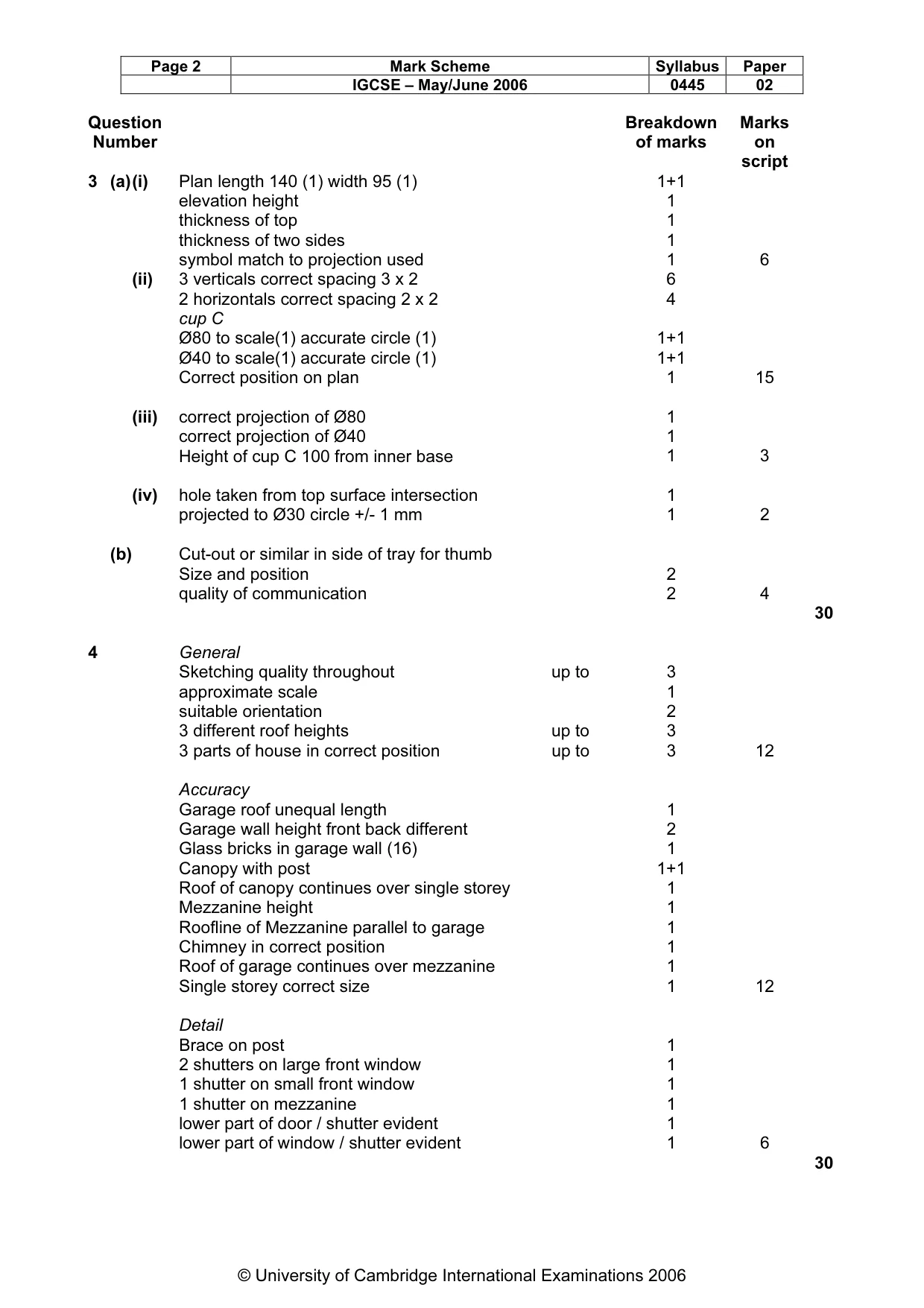
Mark scheme, page 3
Page 2 Mark Scheme Syllabus Paper IGCSE – May/June 2006 0445 02 © University of Cambridge International Examinations 2006 Question Number Breakdown of marks Marks on script 3 (a) (i) Plan length 140 (1) width 95 (1) elevation height thickness of top thickness of two sides symbol match to projection used 1+1 1 1 1 1 6 (ii) 3 verticals correct spacing 3 x 2 2 horizontals correct spacing 2 x 2 cup C Ø80 to scale(1) accurate circle (1) Ø40 to scale(1) accurate circle (1) Correct position on plan 6 4 1+1 1+1 1 15 (iii) correct projection of Ø80 correct projection of Ø40 Height of cup C 100 from inner base 1 1 1 3 (iv) hole taken from top surface intersection projected to Ø30 circle +/- 1 mm 1 1 2 (b) Cut-out or similar in side of tray for thumb Size and position quality of communication 2 2 4 30 4 General Sketching quality throughout up to approximate scale suitable orientation 3 different roof heights up to 3 parts of house in correct position up to 3 1 2 3 3 12 Accuracy Garage roof unequal length Garage wall height front back different Glass bricks in garage wall (16) Canopy with post Roof of canopy continues over single storey Mezzanine height Roofline of Mezzanine parallel to garage Chimney in correct position Roof of garage continues over mezzanine Single storey correct size 1 2 1 1+1 1 1 1 1 1 1 12 Detail Brace on post 2 shutters on large front window 1 shutter on small front window 1 shutter on mezzanine lower part of door / shutter evident lower part of window / shutter evident 1 1 1 1 1 1 6 30
What you needed in this session
Cambridge’s own grade thresholds for 2006 May/June, Paper 2 · Variant 1. A higher threshold means an easier paper — the bar moves with how the cohort did.