Cambridge A Level Physics 9702 — 2006 Oct/Nov Paper 5 · Variant 1
9702/51/O/N/06 · 30 marks · ≈34 min
The question paper and its mark scheme, free to read here and free to download. This is Cambridge’s own paper, exactly as it was sat.
Question paper12 pages

Mark scheme4 pages
Answers below. Sit the paper first if you are practising.
Paper as text
Question paper, page 1
This document consists of 10 printed pages and 2 blank pages. SPA (SJF3718/CG) T01299/2 © UCLES 2006 [Turn over UNIVERSITY OF CAMBRIDGE INTERNATIONAL EXAMINATIONS General Certificate of Education Advanced Level PHYSICS 9702/05 Paper 5 Practical Test October/November 2006 1 hour 30 minutes Candidates answer on the Question Paper. Additional Materials: As listed in the Confidential Instructions. READ THESE INSTRUCTIONS FIRST Write your Centre number, candidate number and name on all the work you hand in. Write in dark blue or black pen. You may use a soft pencil for any diagrams, graphs or rough working. Do not use staples, paper clips, highlighters, glue or correction fluid. Answer all questions. You are expected to record all your observations as soon as these observations are made, and to plan the presentation of the records so that it is not necessary to make a fair copy of them. The working of the answers is to be handed in. Marks are mainly given for a clear record of the observations actually made, for their suitability and accuracy, and for the use made of them. Additional answer paper and graph paper should be submitted only if it becomes necessary to do so. You are reminded of the need for good English and clear presentation in your answers. At the end of the examination, fasten all your work securely together. Centre Number Candidate Number Name For Examiner’s Use 1 2 Total
Question paper, page 2
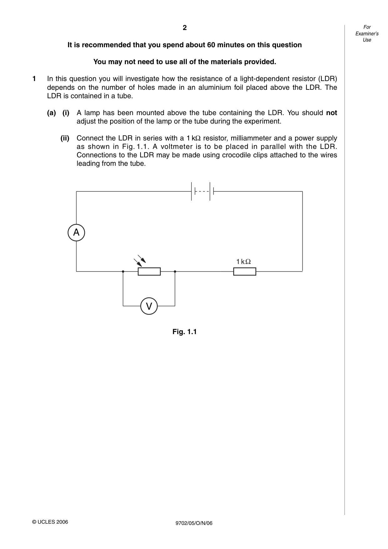
It is recommended that you spend about 60 minutes on this question You may not need to use all of the materials provided. 1 In this question you will investigate how the resistance of a light-dependent resistor (LDR) depends on the number of holes made in an aluminium foil placed above the LDR. The LDR is contained in a tube. (a) (i) A lamp has been mounted above the tube containing the LDR. You should not adjust the position of the lamp or the tube during the experiment. (ii) Connect the LDR in series with a 1 kΩresistor, milliammeter and a power supply as shown in Fig. 1.1. A voltmeter is to be placed in parallel with the LDR. Connections to the LDR may be made using crocodile clips attached to the wires leading from the tube. Fig. 1.1 2 For Examiner’s Use 9702/05/O/N/06 © UCLES 2006 A V 1 k
Question paper, page 3
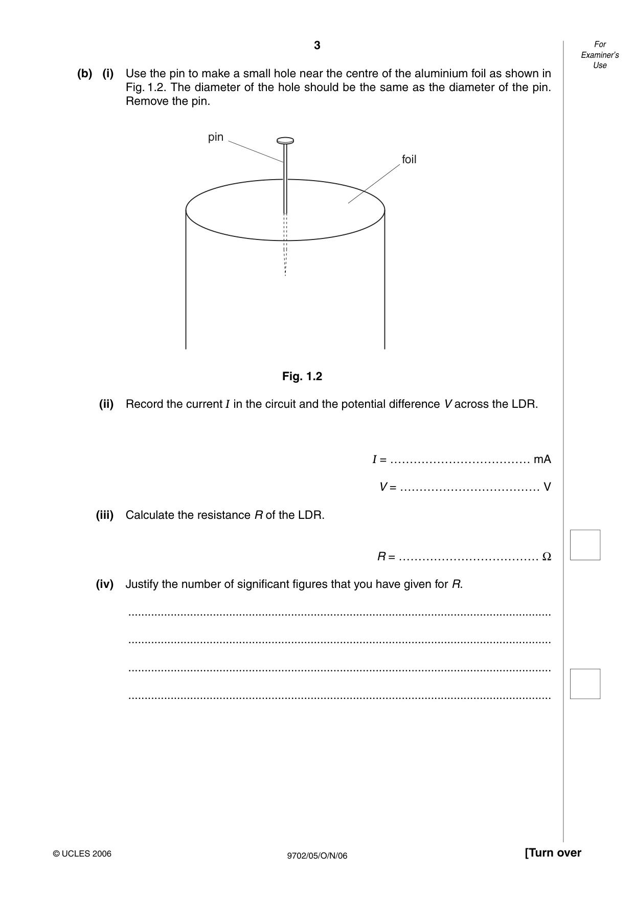
(b) (i) Use the pin to make a small hole near the centre of the aluminium foil as shown in Fig. 1.2. The diameter of the hole should be the same as the diameter of the pin. Remove the pin. Fig. 1.2 (ii) Record the current I in the circuit and the potential difference V across the LDR. I = ……………………………… mA V = ……………………………… V (iii) Calculate the resistance R of the LDR. R = ……………………………… Ω (iv) Justify the number of significant figures that you have given for R. … … … … 3 [Turn over For Examiner’s Use 9702/05/O/N/06 © UCLES 2006 pin foil
Question paper, page 4
(c) Make another, separate pinhole close to the centre of the foil. Repeat (b) (ii) and (iii) until you have six sets of readings for R and the number N of pinholes in the foil where 1 < N < 6. Include values of lg(R/Ω) and lg N in your table of results. (d) (i) Plot a graph of lg(R/Ω) (y-axis) against lg N (x-axis). (ii) Draw the line of best fit. (iii) Determine the gradient and y-intercept of this line. gradient = ………………………………. y-intercept = …………………………….. 4 For Examiner’s Use 9702/05/O/N/06 © UCLES 2006
Question paper, page 5
5 [Turn over For Examiner’s Use 9702/05/O/N/06 © UCLES 2006
Question paper, page 6
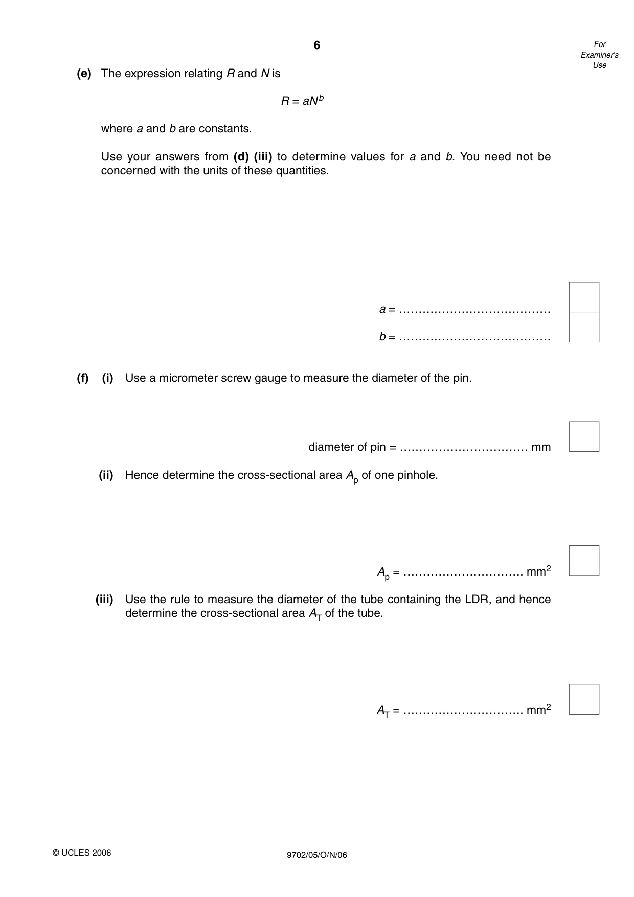
(e) The expression relating R and N is R = aNb where a and b are constants. Use your answers from (d) (iii) to determine values for a and b. You need not be concerned with the units of these quantities. a = ………………………………… b = ………………………………… (f) (i) Use a micrometer screw gauge to measure the diameter of the pin. diameter of pin = …………………………… mm (ii) Hence determine the cross-sectional area Ap of one pinhole. Ap = …………………………. mm2 (iii) Use the rule to measure the diameter of the tube containing the LDR, and hence determine the cross-sectional area AT of the tube. AT = …………………………. mm2 6 For Examiner’s Use 9702/05/O/N/06 © UCLES 2006
Question paper, page 7
(iv) Use your values from (ii) and (iii) to find the number of holes equivalent to the cross-sectional area of the tube. number of holes = …………………………………… (g) Use your answers from (e) and (f) to determine a value for the resistance of the LDR if the foil were to be removed from the end of the tube. It is not necessary to check this value experimentally. R = ………………………………… Ω 7 [Turn over For Examiner’s Use 9702/05/O/N/06 © UCLES 2006
Question paper, page 8
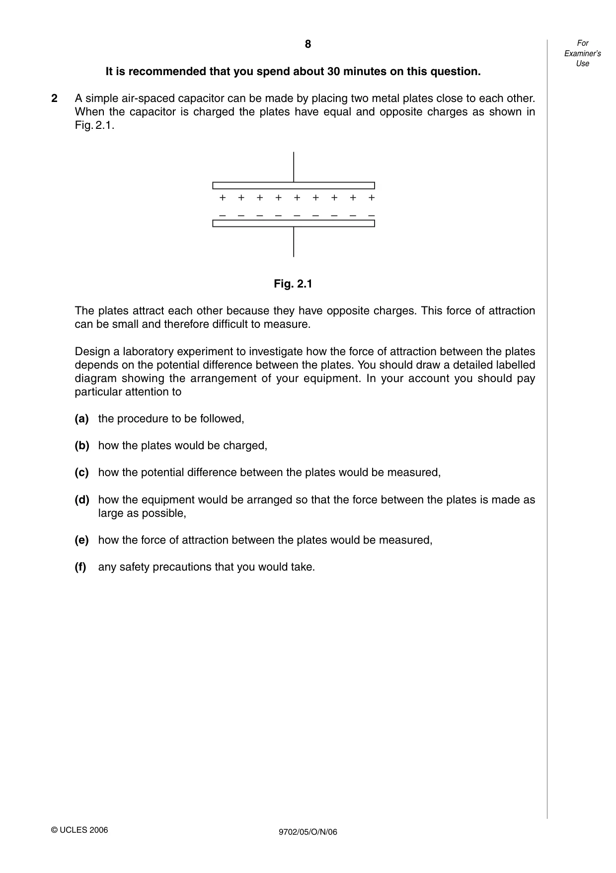
It is recommended that you spend about 30 minutes on this question. 2 A simple air-spaced capacitor can be made by placing two metal plates close to each other. When the capacitor is charged the plates have equal and opposite charges as shown in Fig. 2.1. Fig. 2.1 The plates attract each other because they have opposite charges. This force of attraction can be small and therefore difficult to measure. Design a laboratory experiment to investigate how the force of attraction between the plates depends on the potential difference between the plates. You should draw a detailed labelled diagram showing the arrangement of your equipment. In your account you should pay particular attention to (a) the procedure to be followed, (b) how the plates would be charged, (c) how the potential difference between the plates would be measured, (d) how the equipment would be arranged so that the force between the plates is made as large as possible, (e) how the force of attraction between the plates would be measured, (f) any safety precautions that you would take. 8 For Examiner’s Use 9702/05/O/N/06 © UCLES 2006 + + + + + + + + + – – – – – – – – –
Question paper, page 9
Diagram … … … … … … … … … … … … … … … 9 [Turn over For Examiner’s Use 9702/05/O/N/06 © UCLES 2006
Question paper, page 10
… … … … … … … … … … … … … … … … … … … … … … … … … … … … 10 For Examiner’s Use 9702/05/O/N/06 © UCLES 2006
Question paper, page 12
BLANK PAGE 12 9702/05/O/N/06 Permission to reproduce items where third-party owned material protected by copyright is included has been sought and cleared where possible. Every reasonable effort has been made by the publisher (UCLES) to trace copyright holders, but if any items requiring clearance have unwittingly been included, the publisher will be pleased to make amends at the earliest possible opportunity. University of Cambridge International Examinations is part of the University of Cambridge Local Examinations Syndicate (UCLES), which is itself a department of the University of Cambridge.
Mark scheme, page 1
UNIVERSITY OF CAMBRIDGE INTERNATIONAL EXAMINATIONS GCE Advanced Subsidiary Level and GCE Advanced Level MARK SCHEME for the October/November 2006 question paper 9702 PHYSICS 9702/05 Paper 5 (Practical), maximum raw mark 30 This mark scheme is published as an aid to teachers and students, to indicate the requirements of the examination. It shows the basis on which Examiners were instructed to award marks. It does not indicate the details of the discussions that took place at an Examiners’ meeting before marking began. All Examiners are instructed that alternative correct answers and unexpected approaches in candidates’ scripts must be given marks that fairly reflect the relevant knowledge and skills demonstrated. Mark schemes must be read in conjunction with the question papers and the report on the examination. The grade thresholds for various grades are published in the report on the examination for most IGCSE, GCE Advanced Level and Advanced Subsidiary Level syllabuses. • CIE will not enter into discussions or correspondence in connection with these mark schemes. CIE is publishing the mark schemes for the October/November 2006 question papers for most IGCSE, GCE Advanced Level and Advanced Subsidiary Level syllabuses and some Ordinary Level syllabuses.
Mark scheme, page 2
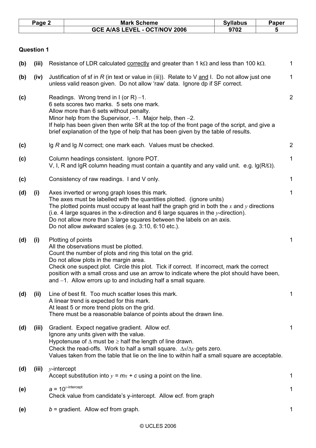
Page 2 Mark Scheme Syllabus Paper GCE A/AS LEVEL - OCT/NOV 2006 9702 5 © UCLES 2006 Question 1 (b) (iii) Resistance of LDR calculated correctly and greater than 1 kΩ and less than 100 kΩ. 1 (b) (iv) Justification of sf in R (in text or value in (iii)). Relate to V and I. Do not allow just one 1 unless valid reason given. Do not allow ‘raw’ data. Ignore dp if SF correct. (c) Readings. Wrong trend in I (or R) −1. 2 6 sets scores two marks. 5 sets one mark. Allow more than 6 sets without penalty. Minor help from the Supervisor, −1. Major help, then −2. If help has been given then write SR at the top of the front page of the script, and give a brief explanation of the type of help that has been given by the table of results. (c) lg R and lg N correct; one mark each. Values must be checked. 2 (c) Column headings consistent. Ignore POT. 1 V, I, R and lgR column heading must contain a quantity and any valid unit. e.g. lg(R/Ω). (c) Consistency of raw readings. I and V only. 1 (d) (i) Axes inverted or wrong graph loses this mark. 1 The axes must be labelled with the quantities plotted. (ignore units) The plotted points must occupy at least half the graph grid in both the x and y directions (i.e. 4 large squares in the x-direction and 6 large squares in the y-direction). Do not allow more than 3 large squares between the labels on an axis. Do not allow awkward scales (e.g. 3:10, 6:10 etc.). (d) (i) Plotting of points 1 All the observations must be plotted. Count the number of plots and ring this total on the grid. Do not allow plots in the margin area. Check one suspect plot. Circle this plot. Tick if correct. If incorrect, mark the correct position with a small cross and use an arrow to indicate where the plot should have been, and −1. Allow errors up to and including half a small square. (d) (ii) Line of best fit. Too much scatter loses this mark. 1 A linear trend is expected for this mark. At least 5 or more trend plots on the grid. There must be a reasonable balance of points about the drawn line. (d) (iii) Gradient. Expect negative gradient. Allow ecf. 1 Ignore any units given with the value. Hypotenuse of ∆ must be ≥ half the length of line drawn. Check the read-offs. Work to half a small square. ∆x/∆y gets zero. Values taken from the table that lie on the line to within half a small square are acceptable. (d) (iii) y-intercept Accept substitution into y = mx + c using a point on the line. 1 (e) a = 10y-intercept 1 Check value from candidate’s y-intercept. Allow ecf. from graph (e) b = gradient. Allow ecf from graph. 1
Mark scheme, page 3
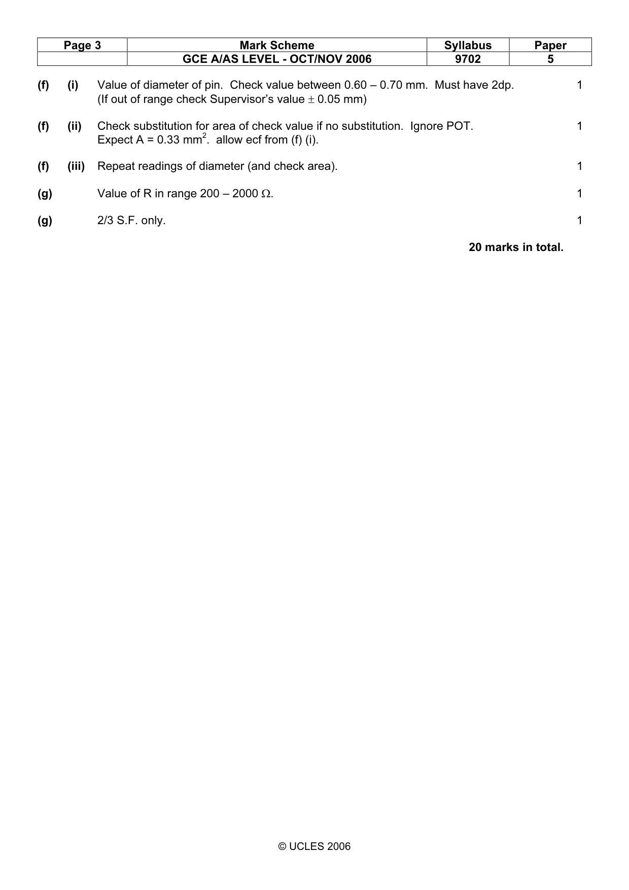
Page 3 Mark Scheme Syllabus Paper GCE A/AS LEVEL - OCT/NOV 2006 9702 5 © UCLES 2006 (f) (i) Value of diameter of pin. Check value between 0.60 – 0.70 mm. Must have 2dp. 1 (If out of range check Supervisor’s value ± 0.05 mm) (f) (ii) Check substitution for area of check value if no substitution. Ignore POT. 1 Expect A = 0.33 mm2. allow ecf from (f) (i). (f) (iii) Repeat readings of diameter (and check area). 1 (g) Value of R in range 200 – 2000 Ω. 1 (g) 2/3 S.F. only. 1 20 marks in total.
Mark scheme, page 4
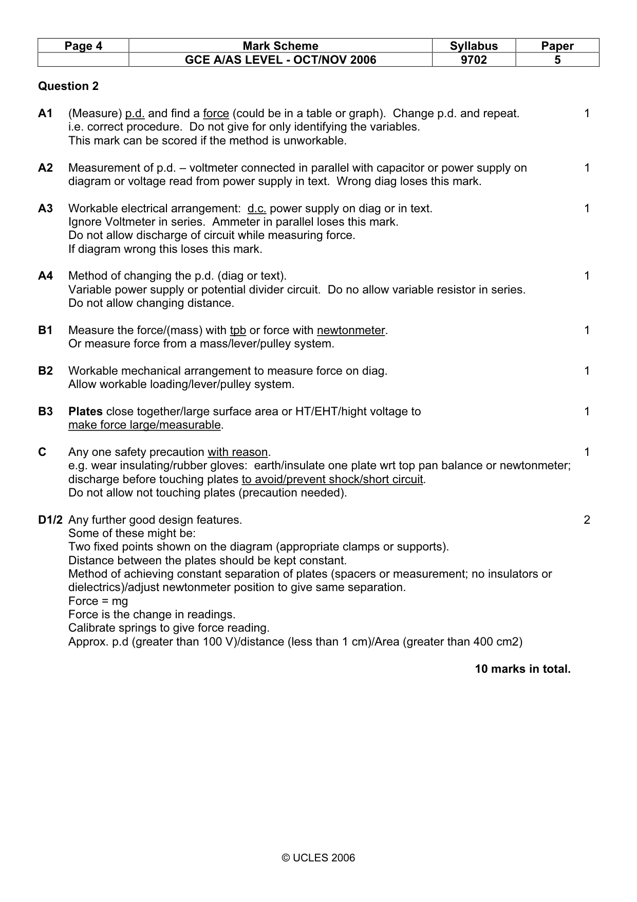
Page 4 Mark Scheme Syllabus Paper GCE A/AS LEVEL - OCT/NOV 2006 9702 5 © UCLES 2006 Question 2 A1 (Measure) p.d. and find a force (could be in a table or graph). Change p.d. and repeat. 1 i.e. correct procedure. Do not give for only identifying the variables. This mark can be scored if the method is unworkable. A2 Measurement of p.d. – voltmeter connected in parallel with capacitor or power supply on 1 diagram or voltage read from power supply in text. Wrong diag loses this mark. A3 Workable electrical arrangement: d.c. power supply on diag or in text. 1 Ignore Voltmeter in series. Ammeter in parallel loses this mark. Do not allow discharge of circuit while measuring force. If diagram wrong this loses this mark. A4 Method of changing the p.d. (diag or text). 1 Variable power supply or potential divider circuit. Do no allow variable resistor in series. Do not allow changing distance. B1 Measure the force/(mass) with tpb or force with newtonmeter. 1 Or measure force from a mass/lever/pulley system. B2 Workable mechanical arrangement to measure force on diag. 1 Allow workable loading/lever/pulley system. B3 Plates close together/large surface area or HT/EHT/hight voltage to 1 make force large/measurable. C Any one safety precaution with reason. 1 e.g. wear insulating/rubber gloves: earth/insulate one plate wrt top pan balance or newtonmeter; discharge before touching plates to avoid/prevent shock/short circuit. Do not allow not touching plates (precaution needed). D1/2 Any further good design features. 2 Some of these might be: Two fixed points shown on the diagram (appropriate clamps or supports). Distance between the plates should be kept constant. Method of achieving constant separation of plates (spacers or measurement; no insulators or dielectrics)/adjust newtonmeter position to give same separation. Force = mg Force is the change in readings. Calibrate springs to give force reading. Approx. p.d (greater than 100 V)/distance (less than 1 cm)/Area (greater than 400 cm2) 10 marks in total.
What you needed in this session
Cambridge’s own grade thresholds for 2006 Oct/Nov, Paper 5 · Variant 1. A higher threshold means an easier paper — the bar moves with how the cohort did.