Cambridge A Level Physics 9702 — 2003 May/June Paper 5 · Variant 1
9702/51/M/J/03
The question paper and its mark scheme, free to read here and free to download. This is Cambridge’s own paper, exactly as it was sat.
Question paper12 pages




Mark scheme
No mark scheme is in the library for this paper.
Paper as text
Question paper, page 1
This document consists of 9 printed pages and 3 blank pages. SP (SM) S45907/3 © CIE 2003 [Turn over CAMBRIDGE INTERNATIONAL EXAMINATIONS General Certificate of Education Advanced Level PHYSICS 9702/05 Paper 5 Practical Test May/June 2003 1 hour 30 minutes Candidates answer on the Question Paper. Additional Materials: As specified in the Confidential Instructions. READ THESE INSTRUCTIONS FIRST Write your Centre number, candidate number and name on all the work you hand in. Write in dark blue or black pen in the spaces provided on the Question Paper. You may use a soft pencil for any diagrams, graphs or rough working. Do not use staples, paper clips, highlighters, glue or correction fluid. Answer both questions. You are expected to record all your observations as soon as these observations are made, and to plan the presentation of the records so that it is not necessary to make a fair copy of them. The working of the answers is to be handed in. Marks are mainly given for a clear record of the observations actually made, for their suitability and accuracy, and for the use made of them. Additional answer paper and graph paper should be submitted only if it becomes necessary to do so. You are reminded of the need for good English and clear presentation in your answers. At the end of the examination, fasten all your work securely together. Centre Number Candidate Number Name If you have been given a label, look at the details. If any details are incorrect or missing, please fill in your correct details in the space given at the top of this page. Stick your personal label here, if provided. For Examiner’s Use 1 2 Total
Question paper, page 2
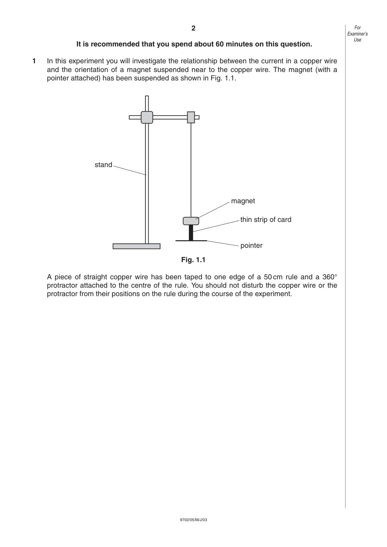
2 9702/05/M/J/03 It is recommended that you spend about 60 minutes on this question. 1 In this experiment you will investigate the relationship between the current in a copper wire and the orientation of a magnet suspended near to the copper wire. The magnet (with a pointer attached) has been suspended as shown in Fig. 1.1. Fig. 1.1 A piece of straight copper wire has been taped to one edge of a 50 cm rule and a 360° protractor attached to the centre of the rule. You should not disturb the copper wire or the protractor from their positions on the rule during the course of the experiment. magnet thin strip of card pointer stand For Examiner’s Use
Question paper, page 3
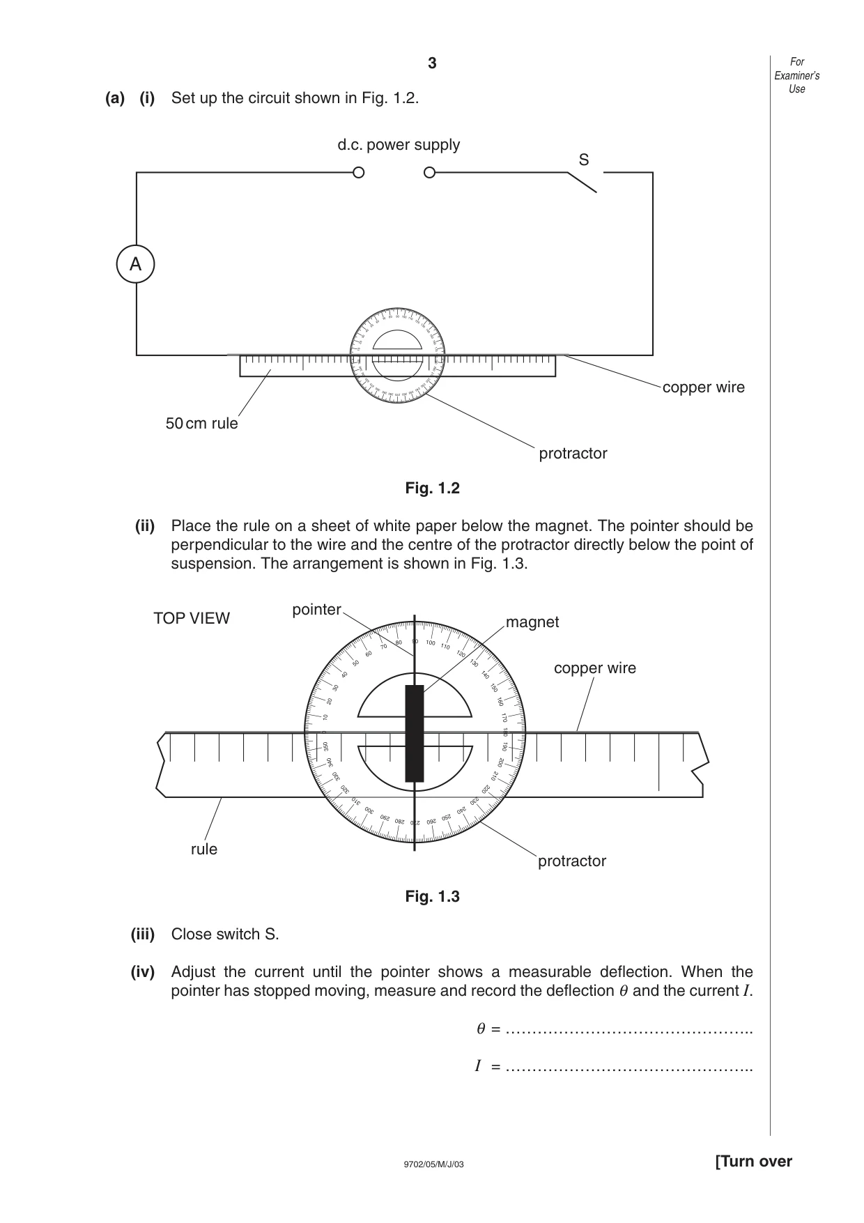
3 9702/05/M/J/03 (a) (i) Set up the circuit shown in Fig. 1.2. Fig. 1.2 (ii) Place the rule on a sheet of white paper below the magnet. The pointer should be perpendicular to the wire and the centre of the protractor directly below the point of suspension. The arrangement is shown in Fig. 1.3. Fig. 1.3 (iii) Close switch S. (iv) Adjust the current until the pointer shows a measurable deflection. When the pointer has stopped moving, measure and record the deflection θ and the current I. θ = ……………………………………….. I = ……………………………………….. 90 100 110 120 130 140 150 160 170 180 80 70 60 50 40 30 20 10 0 270 280 290 300 310 320 330 340 350 260 250 240 230 220 210 200 190 copper wire protractor rule TOP VIEW pointer magnet 90 100 110 120 130 140 150 160 170 180 80 70 60 50 40 30 20 10 0 270 280 290 300 310 320 330 340 350 260 250 240 230 220 210 200 190 A d.c. power supply S protractor copper wire 50 cm rule For Examiner’s Use [Turn over
Question paper, page 4
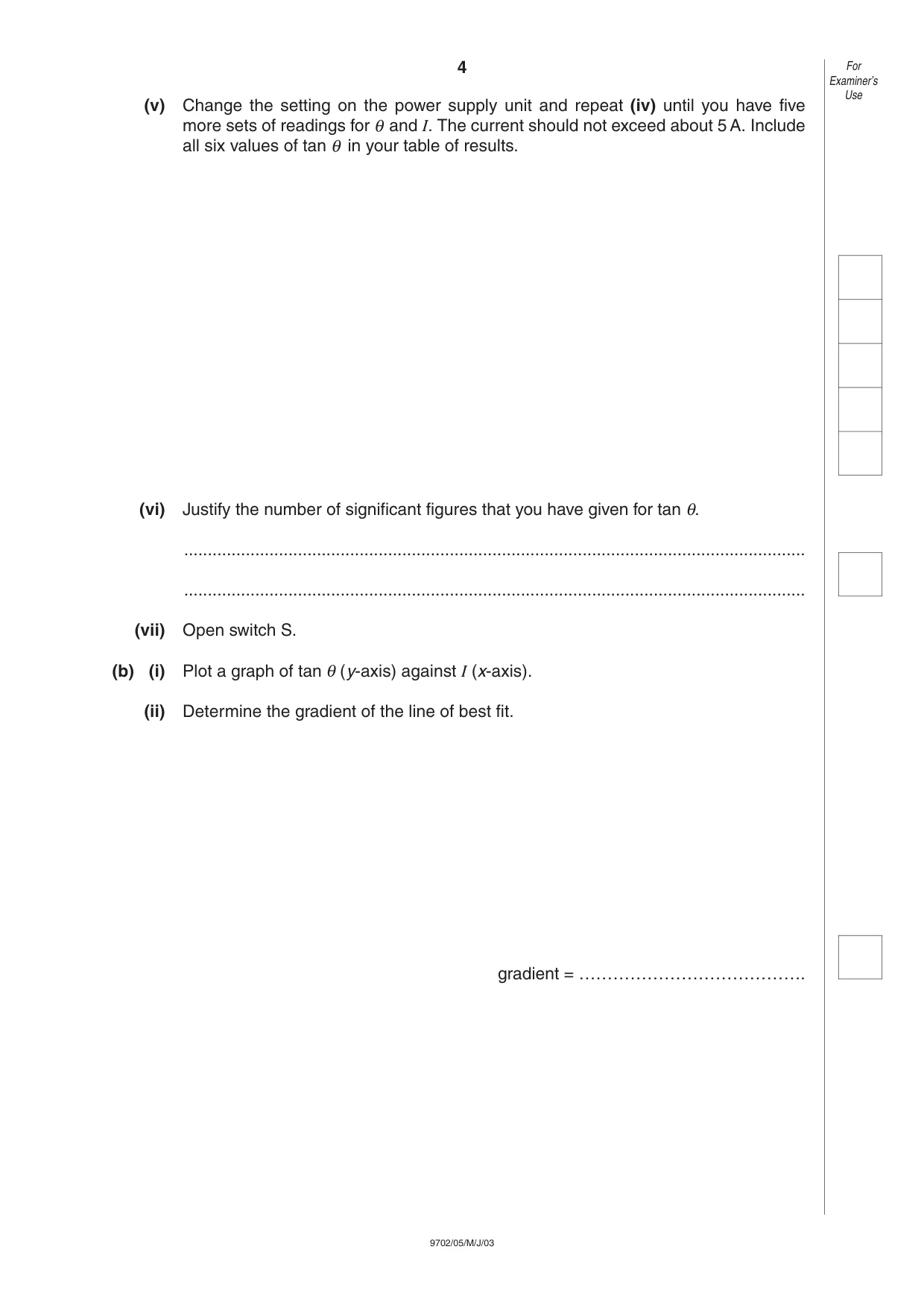
4 9702/05/M/J/03 (v) Change the setting on the power supply unit and repeat (iv) until you have five more sets of readings for θ and I. The current should not exceed about 5 A. Include all six values of tan θ in your table of results. (vi) Justify the number of significant figures that you have given for tan θ. … … (vii) Open switch S. (b) (i) Plot a graph of tan θ (y-axis) against I (x-axis). (ii) Determine the gradient of the line of best fit. gradient = …………………………………. For Examiner’s Use
Question paper, page 5
5 9702/05/M/J/03 For Examiner’s Use [Turn over
Question paper, page 6
6 9702/05/M/J/03 (c) The formula which relates θ and I is tan θ = kI where k is a constant. Use your answer from (b)(ii) to state the value of k. Include an appropriate unit with your value. k = ………………………… (d) (i) Use the results from your experiment to calculate a value for θ when the current in the copper wire is 15 A. θ = ………………………………………. (ii) Give one reason why it may be difficult to verify this experimentally. … … … For Examiner’s Use
Question paper, page 7
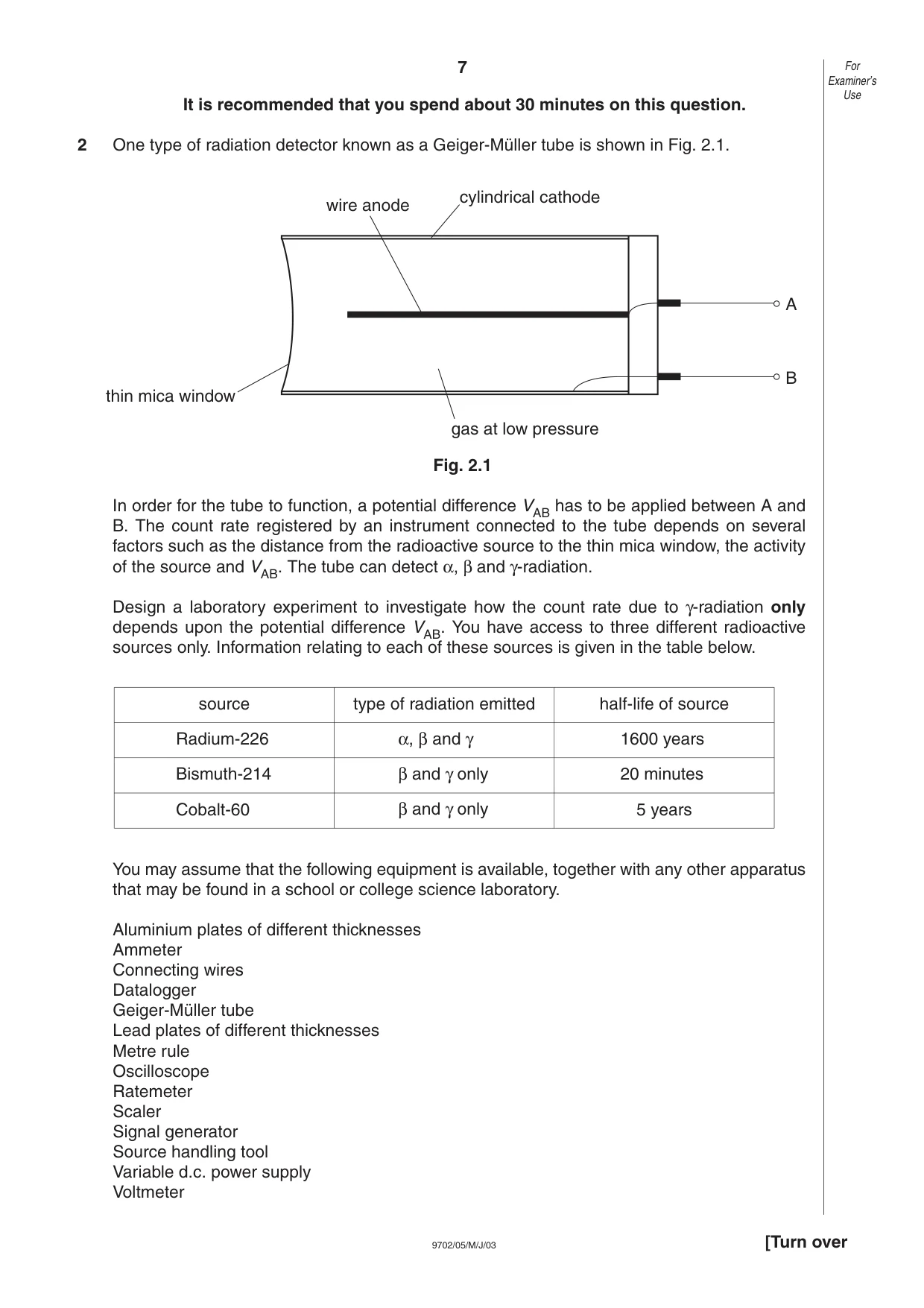
7 9702/05/M/J/03 It is recommended that you spend about 30 minutes on this question. 2 One type of radiation detector known as a Geiger-Müller tube is shown in Fig. 2.1. Fig. 2.1 In order for the tube to function, a potential difference VAB has to be applied between A and B. The count rate registered by an instrument connected to the tube depends on several factors such as the distance from the radioactive source to the thin mica window, the activity of the source and VAB. The tube can detect α, β and γ-radiation. Design a laboratory experiment to investigate how the count rate due to γ-radiation only depends upon the potential difference VAB. You have access to three different radioactive sources only. Information relating to each of these sources is given in the table below. You may assume that the following equipment is available, together with any other apparatus that may be found in a school or college science laboratory. Aluminium plates of different thicknesses Ammeter Connecting wires Datalogger Geiger-Müller tube Lead plates of different thicknesses Metre rule Oscilloscope Ratemeter Scaler Signal generator Source handling tool Variable d.c. power supply Voltmeter wire anode cylindrical cathode thin mica window gas at low pressure A B For Examiner’s Use [Turn over source Radium-226 Bismuth-214 Cobalt-60 α, β and γ β and γ only β and γ only 1600 years 20 minutes 5 years type of radiation emitted half-life of source
Question paper, page 8
8 9702/05/M/J/03 You should draw a diagram showing the arrangement of your apparatus. In your account you should pay particular attention to (a) which source you would use, giving a reason for your choice, (b) the procedure to be followed, including how the count rate would be measured, (c) the control of variables, (d) any safety precautions you would take. … … … … … … … … … For Examiner’s Use
Question paper, page 9
9 9702/05/M/J/03 … … … … … … … … … … … … … … … … … … … … … … … … … … … … For Examiner’s Use