Cambridge A Level Physics 9702 — 2002 Oct/Nov Paper 5 · Variant 1
9702/51/O/N/02
The question paper and its mark scheme, free to read here and free to download. This is Cambridge’s own paper, exactly as it was sat.
Question paper12 pages



Mark scheme5 pages
Answers below. Sit the paper first if you are practising.
Paper as text
Question paper, page 1
TIME 1 hour 30 minutes INSTRUCTIONS TO CANDIDATES Write your name, Centre number and candidate number in the spaces at the top of this page. Answer both questions. Write your answers in the spaces provided on the question paper. You are expected to record all your observations as soon as these observations are made, and to plan the presentation of the records so that it is not necessary to make a fair copy of them. The working of the answers is to be handed in. Marks are mainly given for a clear record of the observations actually made, for their suitability and accuracy, and for the use made of them. INFORMATION FOR CANDIDATES Additional answer paper and graph paper should be submitted only if it becomes necessary to do so. You are reminded of the need for good English and clear presentation in your answers. CAMBRIDGE INTERNATIONAL EXAMINATIONS General Certificate of Education Advanced Level PHYSICS 9702/5 PAPER 5 A2 Practical OCTOBER/NOVEMBER SESSION 2002 1 hour 30 minutes Candidates answer on the question paper. Additional materials: As specified in Instructions to Supervisors Graph paper This question paper consists of 7 printed pages, 2 lined pages and 3 blank pages. SPA (CW/CG) S21694/2 © CIE 2002 [Turn over Candidate Centre Number Number Candidate Name FOR EXAMINER’S USE 1 2 TOTAL
Question paper, page 2
2 9702/5/O/N/02 BLANK PAGE DO NOT WRITE IN THIS SPACE
Question paper, page 3
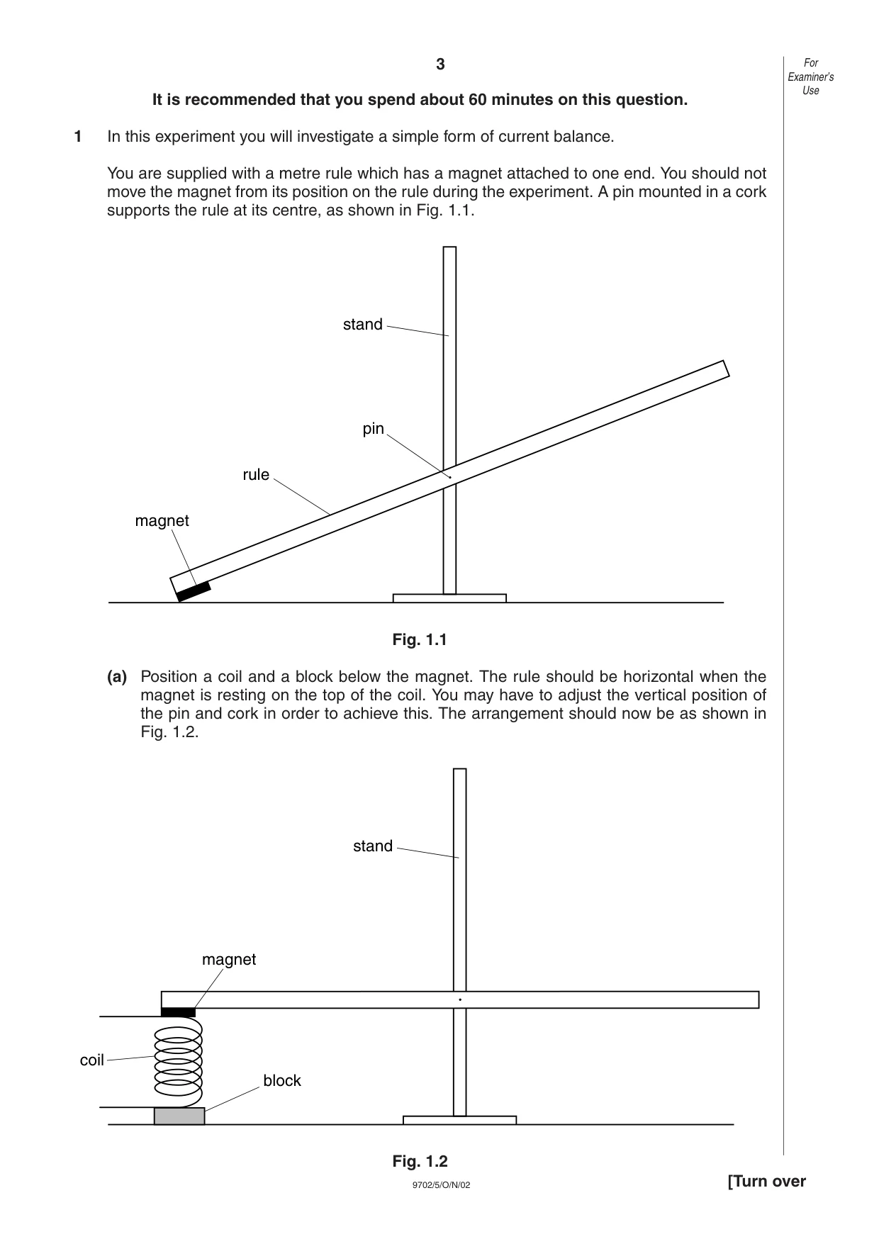
3 9702/5/O/N/02 It is recommended that you spend about 60 minutes on this question. 1 In this experiment you will investigate a simple form of current balance. You are supplied with a metre rule which has a magnet attached to one end. You should not move the magnet from its position on the rule during the experiment. A pin mounted in a cork supports the rule at its centre, as shown in Fig. 1.1. Fig. 1.1 (a) Position a coil and a block below the magnet. The rule should be horizontal when the magnet is resting on the top of the coil. You may have to adjust the vertical position of the pin and cork in order to achieve this. The arrangement should now be as shown in Fig. 1.2. Fig. 1.2 stand magnet block coil stand pin rule magnet For Examiner’s Use [Turn over
Question paper, page 4
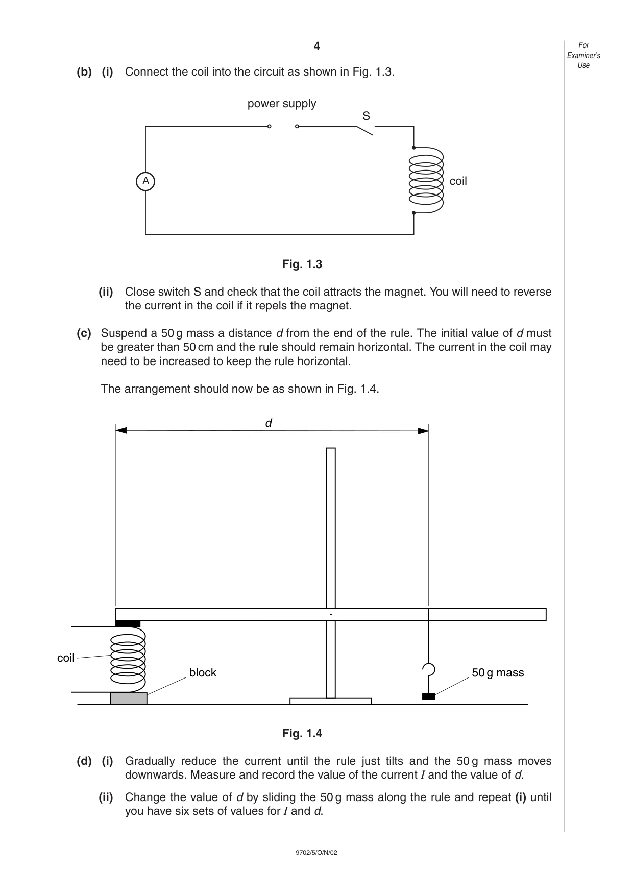
4 9702/5/O/N/02 (b) (i) Connect the coil into the circuit as shown in Fig. 1.3. Fig. 1.3 (ii) Close switch S and check that the coil attracts the magnet. You will need to reverse the current in the coil if it repels the magnet. (c) Suspend a 50 g mass a distance d from the end of the rule. The initial value of d must be greater than 50 cm and the rule should remain horizontal. The current in the coil may need to be increased to keep the rule horizontal. The arrangement should now be as shown in Fig. 1.4. Fig. 1.4 (d) (i) Gradually reduce the current until the rule just tilts and the 50 g mass moves downwards. Measure and record the value of the current I and the value of d. (ii) Change the value of d by sliding the 50 g mass along the rule and repeat (i) until you have six sets of values for I and d. block d 50g mass coil A power supply S coil For Examiner’s Use
Question paper, page 5
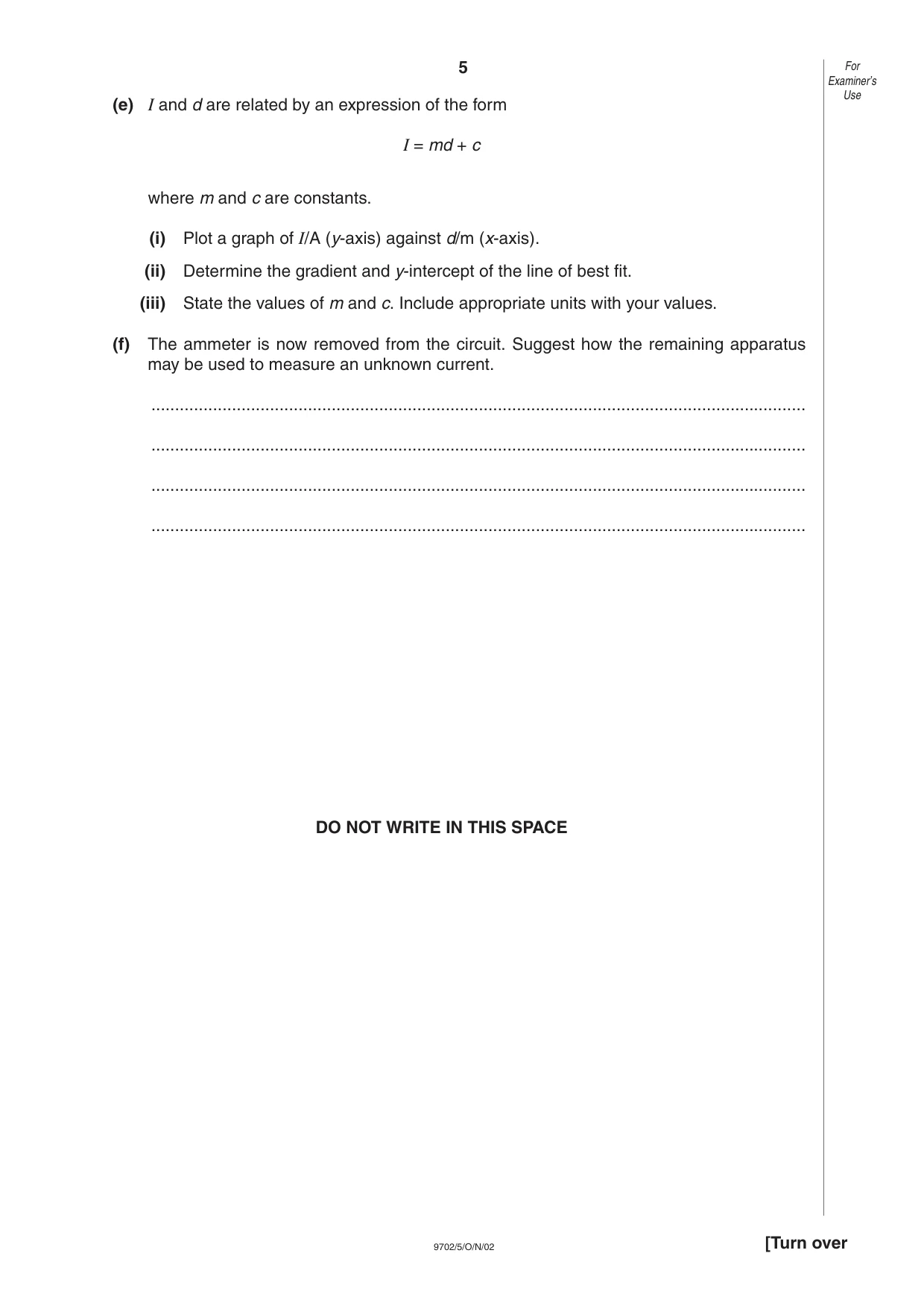
5 9702/5/O/N/02 (e) I and d are related by an expression of the form I = md + c where m and c are constants. (i) Plot a graph of I/A (y-axis) against d/m (x-axis). (ii) Determine the gradient and y-intercept of the line of best fit. (iii) State the values of m and c. Include appropriate units with your values. (f) The ammeter is now removed from the circuit. Suggest how the remaining apparatus may be used to measure an unknown current. … … … … DO NOT WRITE IN THIS SPACE For Examiner’s Use [Turn over
Question paper, page 6
6 9702/5/O/N/02 Measurements and calculations For Examiner’s Use M R A
Question paper, page 7
7 9702/5/O/N/02 Graph grid For Examiner’s Use [Turn over G
Question paper, page 8
8 9702/5/O/N/02 It is recommended that you spend about 30 minutes on this question. 2 Many musical instruments contain wires which are stretched between two fixed supports. These wires are often made to resonate in their fundamental mode of vibration, as shown in Fig. 2.1. Fig. 2.1 The frequency of the note produced by the wire when it vibrates depends on (i) the length of the wire between the supports, (ii) the tension in the wire, (iii) the mass per unit length of the wire. Design an experiment to investigate how the resonant frequency of a wire vibrating in its fundamental mode depends on the tension in the wire. You should draw a diagram showing the arrangement of your equipment. In your account you should pay particular attention to (a) the method by which the wire would be made to vibrate at a known frequency, (b) how the resonant frequency and the tension would be measured, (c) the procedure to be followed, (d) control of variables, (e) any safety precautions which you would take. For Examiner’s Use
Question paper, page 9
9 9702/5/O/N/02 … … … … … … … … … … … … … … For Examiner’s Use [Turn over
Question paper, page 10
10 9702/5/O/N/02 … … … … … … … … … … … … … … … … … … … … … … … … … … … … For Examiner’s Use
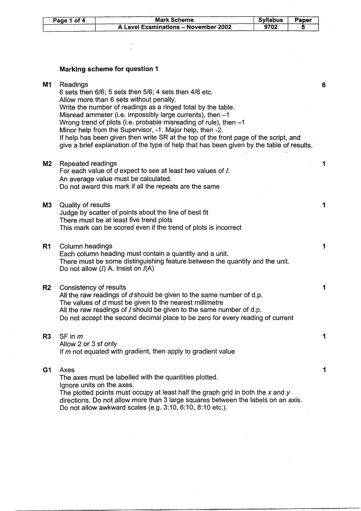
Mark scheme, page 1
CAMBRIDGE INTERNATIONAL EXAMINATIONS NOVEMBER 2002 GCE Advanced Level UNIVERSITY of CAMBRIDGE Local Examinations Syndicate
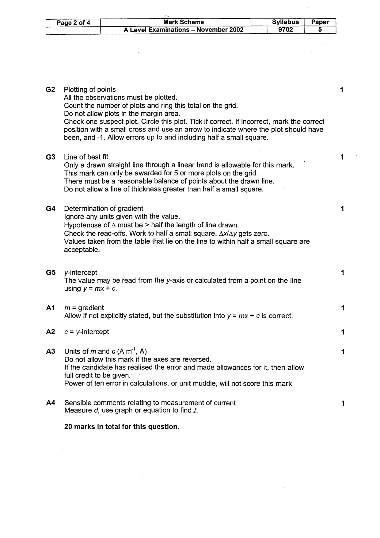
Mark scheme, page 2
Page 1 of 4 Mark Scheme Syllabus | Paper A Level Examinations ~ November 2002 9702 I 5 M1 M2 M3 R1 R3 G1 Marking scheme for question Readings 6 sets then 6/6; 5 sets then 5/6; 4 4 sets then 4/6 etc. Allow more than 6 sets without penalty. Write the number of readings as a ringed total by the table. Misread ammeter (i.e. impossibly large currents), then —1 Wrong trend of plots (i.e. probable misreading of rule), then —1 Minor help from the Supervisor, -1. Major help, then -2. If help has been given then write SR at the top of the front page of the script, and give a brief explanation of the type of help that has been given by the table of results. Repeated readings For each value of d expect to see at least two values of J. An average value must be calculated. Do not award this mark if all the Quality of results repeats are the same Judge by scatter of points about the line of best fit There must be at least five trend plots This mark can be scored even if the trend of plots is incorrect Column headings Each column heading must contain a quantity and a unit. There must be some distinguishing feature between the quantity and the unit. Do not allow (/) A. Insist on /(A) Consistency of results All the raw readings of d should be given to the same number of d.p. The values of d must be given to the nearest millimetre All the raw readings of J should be given to the same number of d.p. Do not accept the second decimal place to be zero for every reading of current SFinm Allow 2 or 3 sf only If m not equated with gradient, then apply to gradient value Axes The axes must be labelled with the quantities plotted. Ignore units on the axes. The plotted points must occupy at least half the graph grid in both the x and y directions. Do not allow more than 3 large squares between the labels on an axis. Do not allow awkward scales (e. .g. 3:10, 6:10, 8:10 etc.).
Mark scheme, page 3
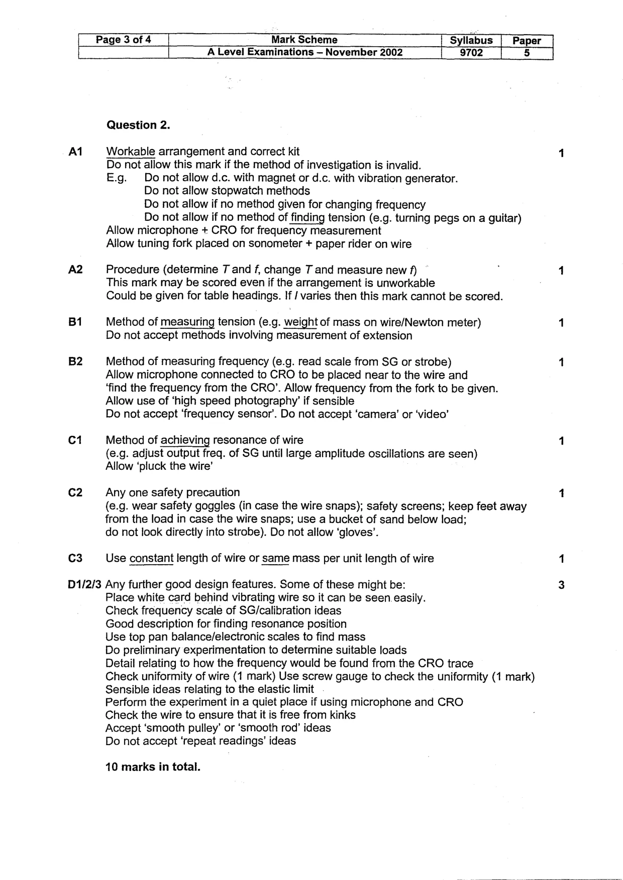
Page 2 of 4 Mark Scheme Syllabus Paper A Level Examinations — November 2002 9702 5 G2 G3 G4 G5 Al A3 A4 Plotting of points All the observations must be plotted. Count the number of plots and ring this total on the grid. Do not allow plots in the margin area. Check one suspect plot. Circle this plot. Tick if correct. If incorrect, mark the correct position with a small cross and use an arrow to indicate where the plot should have been, and -1. Allow errors up to and including half a small square. Line of best fit Only a drawn straight line through a linear trend is allowable for this mark. This mark can only be awarded for 5 or more plots on the grid. There must be a reasonable balance of points about the drawn line. Do not allow a line of thickness greater than half a small square. Determination of gradient Ignore any units given with the value. Hypotenuse of A must be > half the length of line drawn. Check the read-offs. Work to half a small square. Ax/Ay gets zero. Values taken from the table that lie on the line to within half a small square are acceptable. y-intercept The value may be read from the y-axis or calculated from a point on the line using y= mx +c. m= gradient Allow if not explicitly stated, but the substitution into y = mx + cis correct. c= y-intercept Units of mand c (Am", A) Do not allow this mark if the axes are reversed. If the candidate has realised the error and made allowances for it, then allow full credit to be given: Power of ten error in calculations, or unit muddle, will not score this mark Sensible comments relating to measurement of current Measure d, use graph or equation to find 7. 20 marks in total for this question.
Mark scheme, page 4
Page 3 of 4 Mark Scheme Syllabus Paper A Level Examinations — November 2002 9702 5 Al B1 B2 C1 c2 c3 Question 2. Workable arrangement and correct kit Do not allow this mark if the method of investigation is invalid. E.g. Do not allow d.c. with magnet or d.c. with vibration generator. Do not allow stopwatch methods Do not allow if no method given for changing frequency Do not allow if no method of finding tension (e.g. turning pegs on a guitar) Allow microphone + CRO for frequency measurement Allow tuning fork placed on sonometer + paper rider on wire Procedure (determine T and f, change T and measure new f) This mark may be scored even if the arrangement is unworkable Could be given for table headings. If / varies then this mark cannot be scored. Method of measuring tension (e.g. weight of mass on wire/Newton meter) Do not accept methods involving measurement of extension Method of measuring frequency (e.g. read scale from SG or strobe) Allow microphone connected to CRO to be placed near to the wire and ‘find the frequency from the CRO’. Allow frequency from the fork to be given. Allow use of ‘high speed photography’ if sensible Do not accept ‘frequency sensor’. Do not accept ‘camera’ or ‘video’ Method of achieving resonance of wire (e.g. adjust output freq. of SG until large amplitude oscillations are seen) Allow ‘pluck the wire’ Any one safety precaution (e.g. wear safety goggles (in case the wire snaps); safety screens; keep feet away from the load in case the wire snaps; use a bucket of sand below load; do not look directly into strobe). Do not allow ‘gloves’. Use constant length of wire or same mass per unit length of wire D1/2/3 Any further good design features. Some of these might be: Place white card behind vibrating wire so it can be seen easily. Check frequency scale of SG/calibration ideas Good description for finding resonance position Use top pan balance/electronic scales to find mass Do preliminary experimentation to determine suitable loads Detail relating to how the frequency would be found from the CRO trace Check uniformity of wire (1 mark) Use screw gauge to check the uniformity (1 mark) Sensible ideas relating to the elastic limit Perform the experiment in a quiet place if using microphone and CRO Check the wire to ensure that it is free from kinks Accept ‘smooth pulley’ or ‘smooth rod’ ideas Do not accept ‘repeat readings’ ideas 10 marks in total.
Mark scheme, page 5
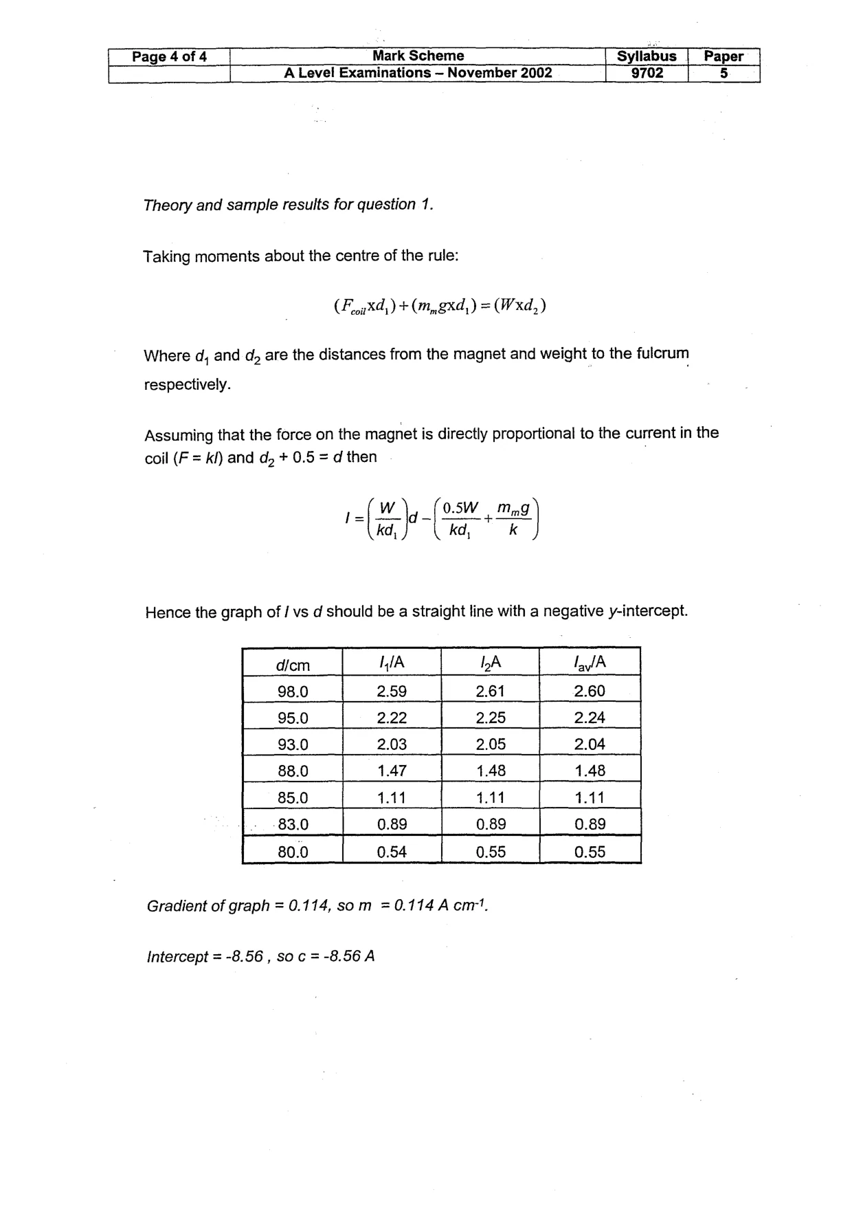
Page 4 of 4 Mark Scheme Syllabus Paper A Level Examinations — November 2002 9702 5 Theory and sample results for question 1. Taking moments about the centre of the rule: (FoorX4,) + (mn, xd, ) = (Wxd,) Where d, and dy are the distances from the magnet and weight to the fulcrum respectively. Assuming that the force on the magnet is directly proportional to the current in the coil (F = k/) and dz + 0.5 = d then l= Wig 0.5W Mn kd, kd, k Hence the graph of / vs d should be a straight line with a negative y-intercept. dicm IIA IDA falA 98.0 2.59 2.61 2.60 95.0 2.22 2.25 2.24 93.0 2.03 [205 2.04 | 88.0 1.47 1.48 1.48 85.0 114 1.11 111 83.0 0.89 0.89 0.89 80.0 0.54 0.55 0.55 Gradient of graph = 0.114, som =0.114A cm". Intercept = -8.56 , soc =-8.56A