Cambridge IGCSE Physics 0625 — 2021 May/June Paper 6 · Variant 2
0625/62/M/J/21 · 4 questions · 40 marks · ≈45 min
The question paper and its mark scheme, free to read here and free to download. This is Cambridge’s own paper, exactly as it was sat.
Question paper12 pages

Mark scheme8 pages
Answers below. Sit the paper first if you are practising.
Questions as text
Q1 · A student determines the density of sand
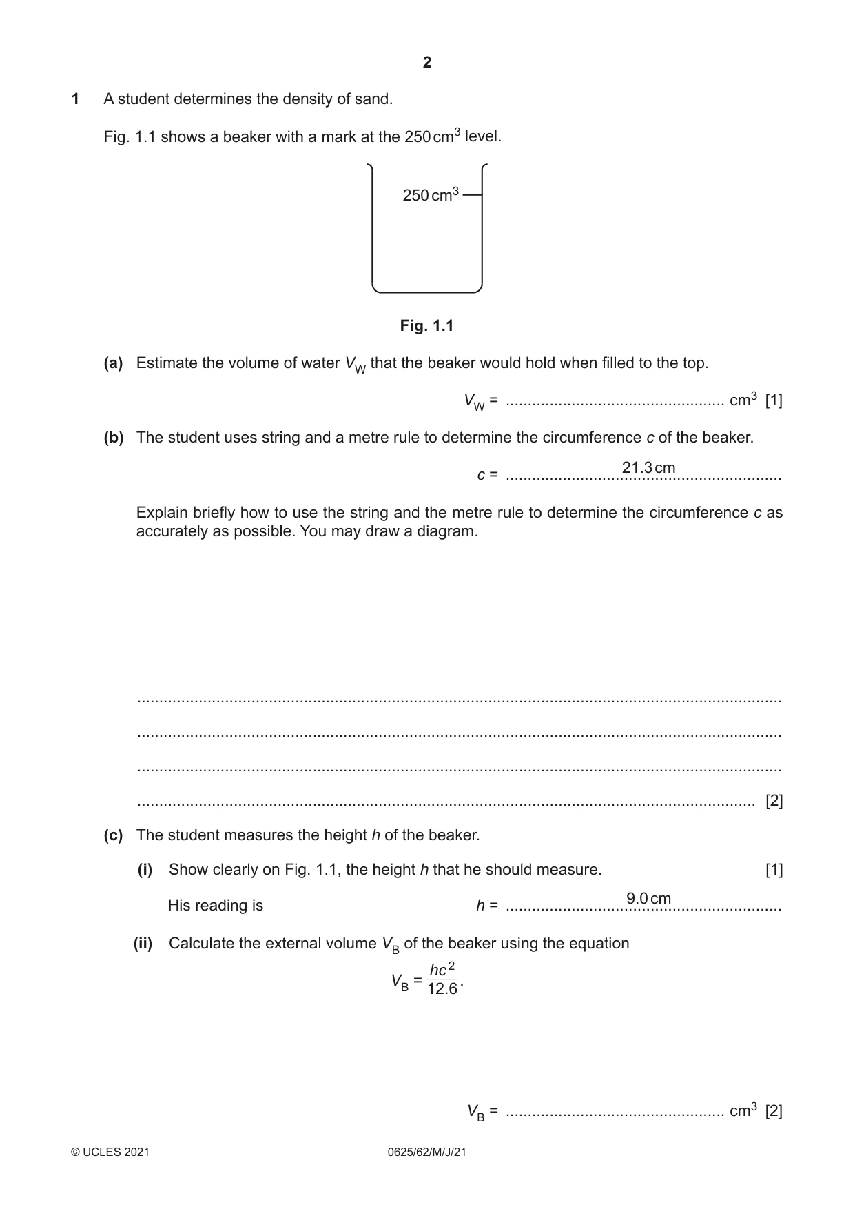
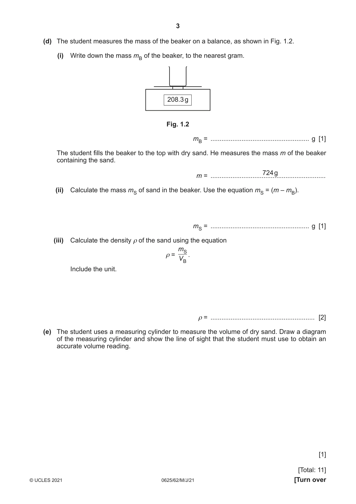
1 A student determines the density of sand. Fig. 1.1 shows a beaker with a mark at the 250 cm3 level. 250 cm3 Fig. 1.1 (a) Estimate the volume of water VW that the beaker would hold when filled to the top. VW = .................................................. cm3 [1] (b) The student uses string and a metre rule to determine the circumference c of the beaker. 21.3 cm c = ............................................................... Explain briefly how to use the string and the metre rule to determine the circumference c as accurately as possible. You may draw a diagram. ................................................................................................................................................... ................................................................................................................................................... ................................................................................................................................................... ............................................................................................................................................. [2] (c) The student measures the height h of the beaker. (i) Show clearly on Fig. 1.1, the height h that he should measure. [1] 9.0 cm His reading is h = ............................................................... (ii) Calculate the external volume VB of the beaker using the equation hc 2 VB = . 12.6 VB = .................................................. cm3 [2] (d) The student measures the mass of the beaker on a balance, as shown in Fig. 1.2. (i) Write down the mass mB of the beaker, to the nearest gram. 208.3 g Fig. 1.2 mB = ...................................................... g [1] The student fills the beaker to the top with dry sand. He measures the mass m of the beaker containing the sand. 724 g m = ............................................................... (ii) Calculate the mass mS of sand in the beaker. Use the equation mS = (m – mB). mS = ...................................................... g [1] (iii) Calculate the density ρ of the sand using the equation mS ρ = . VB Include the unit. ρ = ......................................................... [2] (e) The student uses a measuring cylinder to measure the volume of dry sand. Draw a diagram of the measuring cylinder and show the line of sight that the student must use to obtain an accurate volume reading. [1] [Total: 11]
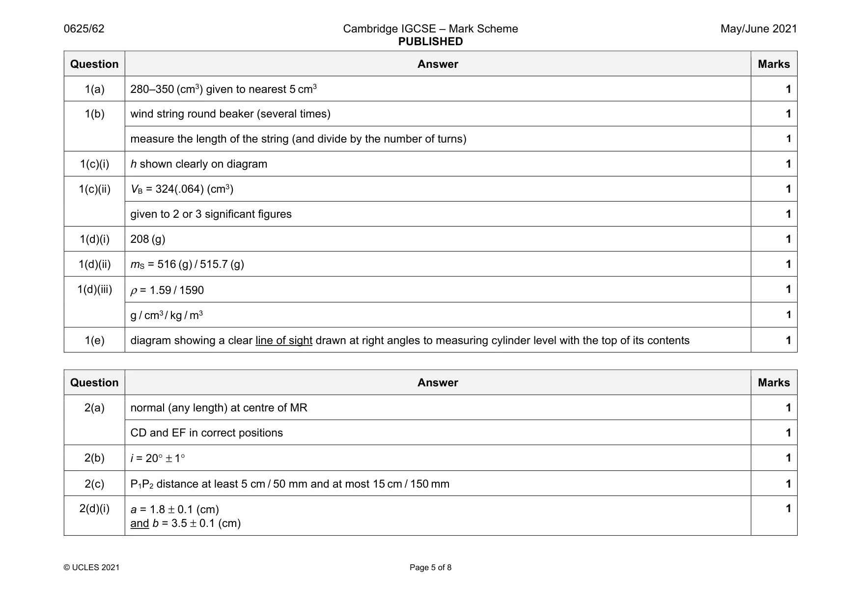
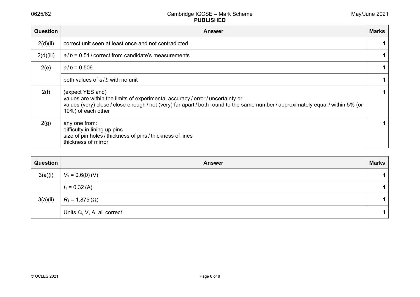
Mark scheme: 1(a) 280–350 (cm3) given to nearest 5 cm3 1 1(b) wind string round beaker (several times) 1 measure the length of the string (and divide by the number of turns) 1 1(c)(i) h shown clearly on diagram 1 1(c)(ii) VB = 324(.064) (cm3) 1 given to 2 or 3 significant figures 1 1(d)(i) 208 (g) 1 1(d)(ii) mS = 516 (g) / 515.7 (g) 1 1(d)(iii) ρ = 1.59 / 1590 1 g / cm3 / kg / m3 1 1(e) diagram showing a clear line of sight drawn at right angles to measuring cylinder level with the top of its contents 1
More questions on Physical quantities and measurement techniques
Q2 · A student investigates the position of the image in a plane mirror
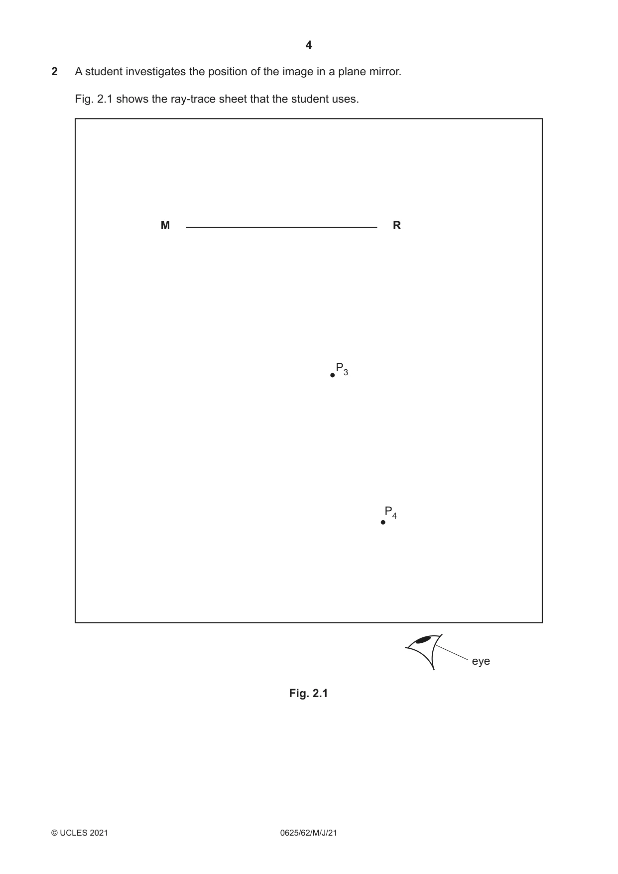
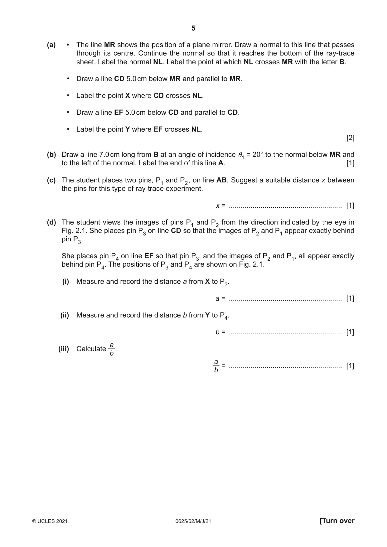
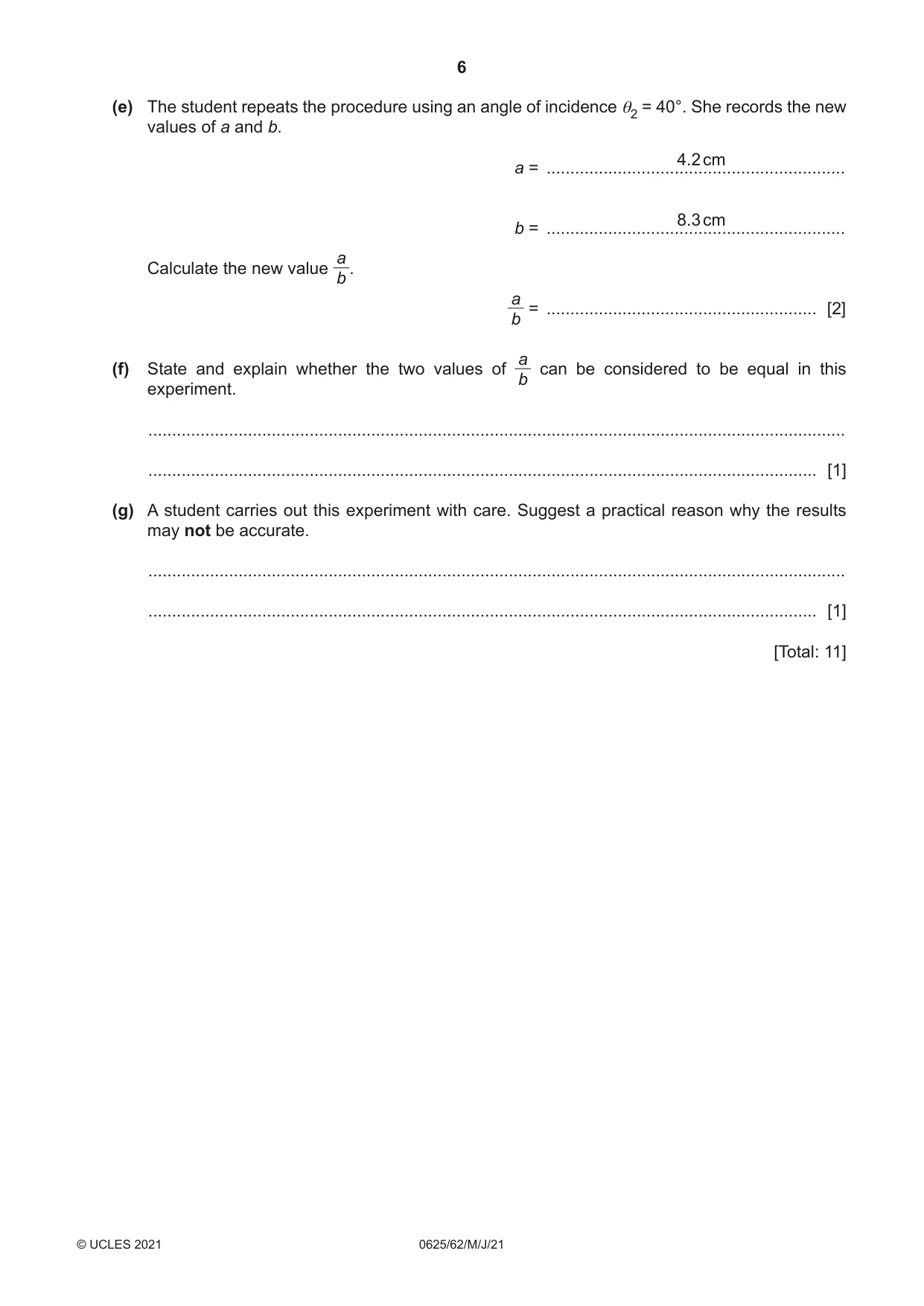
2 A student investigates the position of the image in a plane mirror. Fig. 2.1 shows the ray-trace sheet that the student uses. M R P3 P4 eye Fig. 2.1 (a) • The line MR shows the position of a plane mirror. Draw a normal to this line that passes through its centre. Continue the normal so that it reaches the bottom of the ray-trace sheet. Label the normal NL. Label the point at which NL crosses MR with the letter B. • Draw a line CD 5.0 cm below MR and parallel to MR. • Label the point X where CD crosses NL. • Draw a line EF 5.0 cm below CD and parallel to CD. • Label the point Y where EF crosses NL. [2] (b) Draw a line 7.0 cm long from B at an angle of incidence θ1 = 20° to the normal below MR and to the left of the normal. Label the end of this line A. [1] (c) The student places two pins, P1 and P2 , on line AB. Suggest a suitable distance x between the pins for this type of ray-trace experiment. x = ......................................................... [1] (d) The student views the images of pins P1 and P2 from the direction indicated by the eye in Fig. 2.1. She places pin P3 on line CD so that the images of P2 and P1 appear exactly behind pin P3. She places pin P4 on line EF so that pin P3, and the images of P2 and P1, all appear exactly behind pin P4. The positions of P3 and P4 are shown on Fig. 2.1. (i) Measure and record the distance a from X to P3. a = ......................................................... [1] (ii) Measure and record the distance b from Y to P4. b = ......................................................... [1] a (iii) Calculate . b a = ......................................................... [1] b (e) The student repeats the procedure using an angle of incidence θ2 = 40°. She records the new values of a and b. 4.2 cm a = ............................................................... 8.3 cm b = ............................................................... a Calculate the new value . b a = ......................................................... [2] b a(f) State and explain whether the two values of can be considered to be equal in this b experiment. ................................................................................................................................................... ............................................................................................................................................. [1] (g) A student carries out this experiment with care. Suggest a practical reason why the results may not be accurate. ................................................................................................................................................... ............................................................................................................................................. [1] [Total: 11]
Mark scheme: 2(a) normal (any length) at centre of MR 1 CD and EF in correct positions 1 2(b) i = 20° ± 1° 1 2(c) P1P2 distance at least 5 cm / 50 mm and at most 15 cm / 150 mm 1 2(d)(i) a = 1.8 ± 0.1 (cm) and b = 3.5 ± 0.1 (cm) 1 Question Answer Marks 2(d)(ii) correct unit seen at least once and not contradicted 1 2(d)(iii) a / b = 0.51 / correct from candidate’s measurements 1 2(e) a / b = 0.506 1 both values of a / b with no unit 1 2(f) (expect YES and) values are within the limits of experimental accuracy / error / uncertainty or values (very) close / close enough / not (very) far apart / both round to the same number / approximately equal / within 5% (or 10%) of each other 1 2(g) any one from: difficulty in lining up pins size of pin holes / thickness of pins / thickness of lines thickness of mirror 1
Q3 · A student investigates resistance
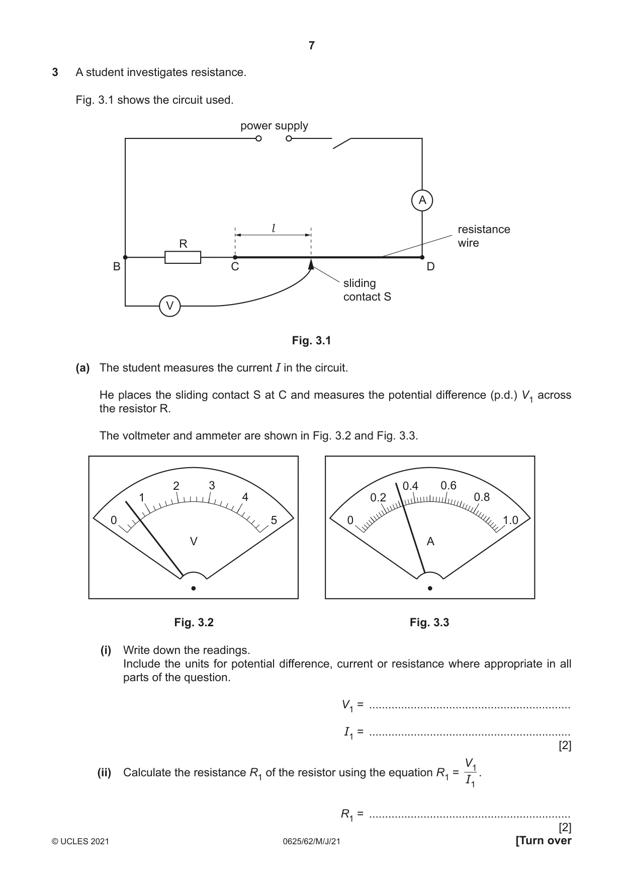
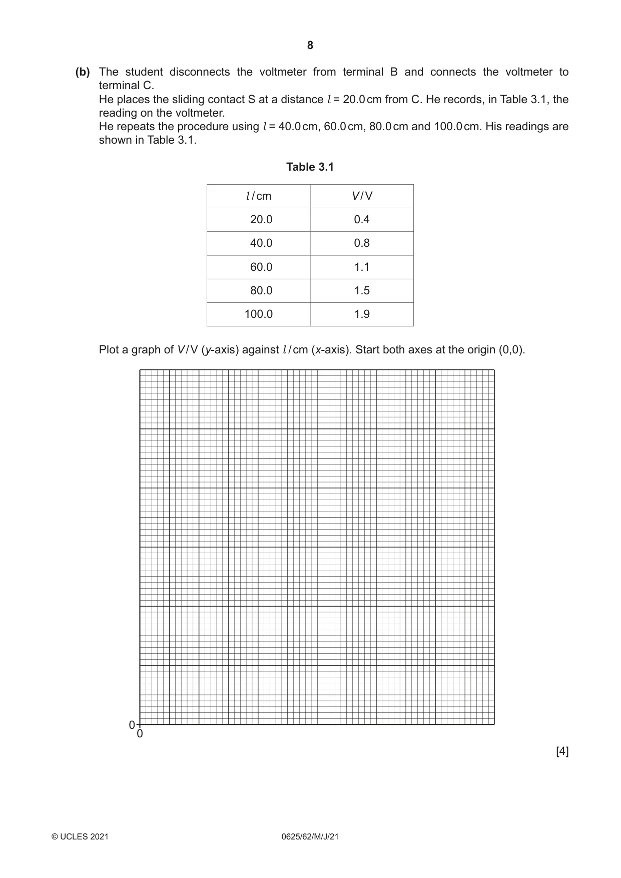
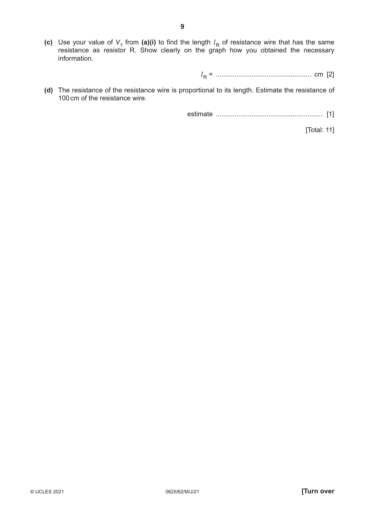
3 A student investigates resistance. Fig. 3.1 shows the circuit used. power supply A l resistance R wire B C D sliding contact S V Fig. 3.1 (a) The student measures the current I in the circuit. He places the sliding contact S at C and measures the potential difference (p.d.) V1 across the resistor R. The voltmeter and ammeter are shown in Fig. 3.2 and Fig. 3.3. 2 3 0.4 0.6 1 4 0.2 0.8 0 5 0 1.0 V A Fig. 3.2 Fig. 3.3 (i) Write down the readings. Include the units for potential difference, current or resistance where appropriate in all parts of the question. V1 = ............................................................... I1 = ............................................................... [2] V1 (ii) Calculate the resistance R1 of the resistor using the equation R1 = . I1 R1 = ............................................................... (b) The student disconnects the voltmeter from terminal B and connects the voltmeter to terminal C. He places the sliding contact S at a distance l = 20.0 cm from C. He records, in Table 3.1, the reading on the voltmeter. He repeats the procedure using l = 40.0 cm, 60.0 cm, 80.0 cm and 100.0 cm. His readings are shown in Table 3.1. Table 3.1 l / cm V / V 20.0 0.4 40.0 0.8 60.0 1.1 80.0 1.5 100.0 1.9 Plot a graph of V / V (y-axis) against l / cm (x-axis). Start both axes at the origin (0,0). 00 [4] (c) Use your value of V1 from (a)(i) to find the length l R of resistance wire that has the same resistance as resistor R. Show clearly on the graph how you obtained the necessary information. l R = ................................................... cm [2] (d) The resistance of the resistance wire is proportional to its length. Estimate the resistance of 100 cm of the resistance wire. estimate ......................................................... [1] [Total: 11]
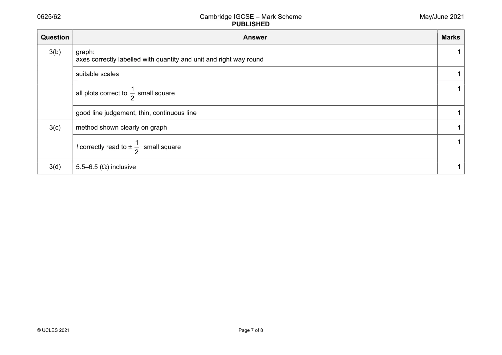
Mark scheme: 3(a)(i) V1 = 0.6(0) (V) 1 I1 = 0.32 (A) 1 3(a)(ii) R1 = 1.875 (Ω) 1 Units Ω, V, A, all correct 1 Question Answer Marks 3(b) graph: axes correctly labelled with quantity and unit and right way round 1 suitable scales 1 all plots correct to 1 2 small square 1 good line judgement, thin, continuous line 1 3(c) method shown clearly on graph 1 l correctly read to ± 1 2 small square 1 3(d) 5.5–6.5 (Ω) inclusive 1
Q4 · A student investigates springs made from different metals
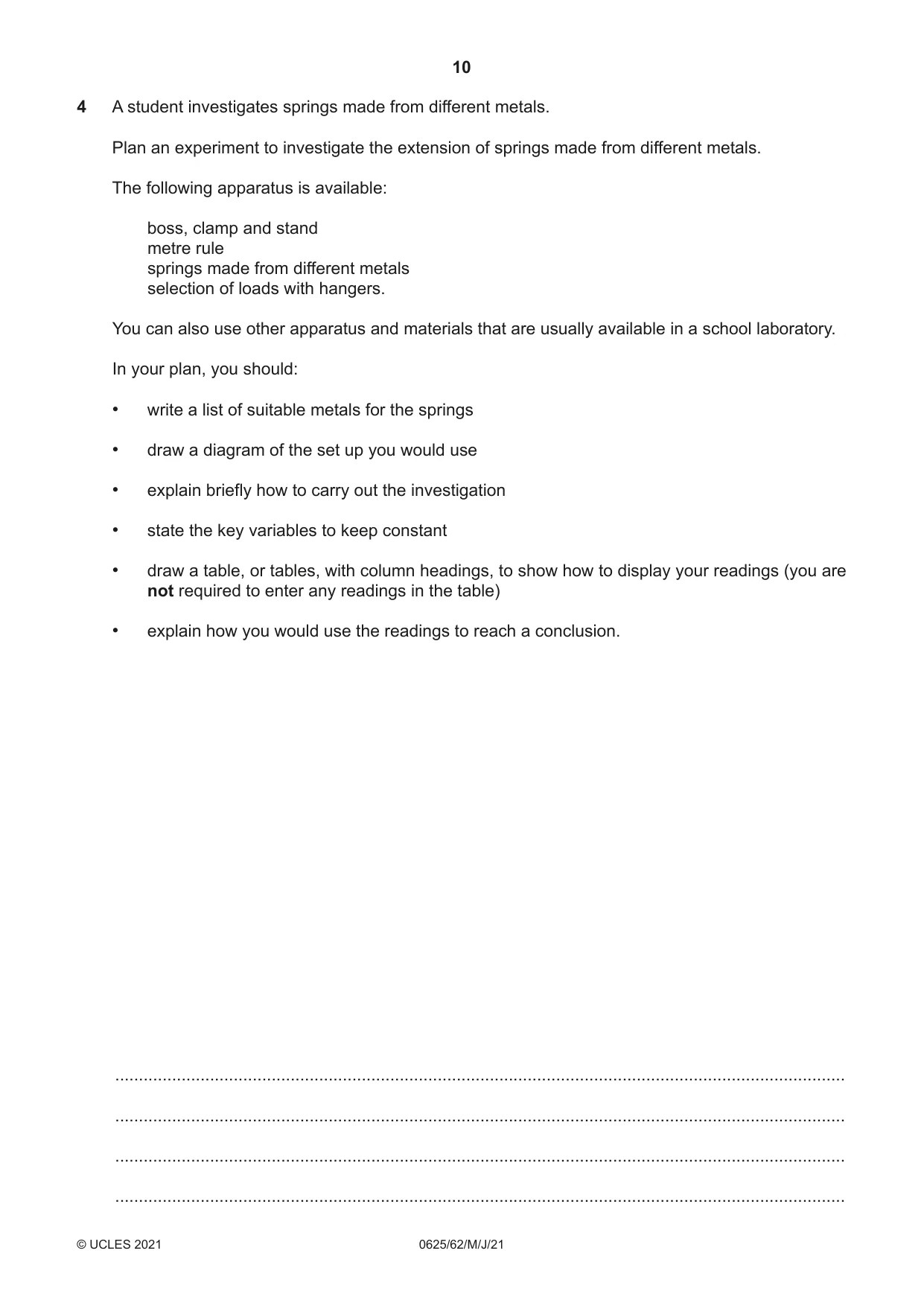
4 A student investigates springs made from different metals. Plan an experiment to investigate the extension of springs made from different metals. The following apparatus is available: boss, clamp and stand metre rule springs made from different metals selection of loads with hangers. You can also use other apparatus and materials that are usually available in a school laboratory. In your plan, you should: • write a list of suitable metals for the springs • draw a diagram of the set up you would use • explain briefly how to carry out the investigation • state the key variables to keep constant • draw a table, or tables, with column headings, to show how to display your readings (you are not required to enter any readings in the table) • explain how you would use the readings to reach a conclusion. .......................................................................................................................................................... .......................................................................................................................................................... .......................................................................................................................................................... .......................................................................................................................................................... .......................................................................................................................................................... .......................................................................................................................................................... .......................................................................................................................................................... .......................................................................................................................................................... .......................................................................................................................................................... .......................................................................................................................................................... .......................................................................................................................................................... .......................................................................................................................................................... .......................................................................................................................................................... .......................................................................................................................................................... .......................................................................................................................................................... .......................................................................................................................................................... .......................................................................................................................................................... .......................................................................................................................................................... .......................................................................................................................................................... .......................................................................................................................................................... .......................................................................................................................................................... .................................................................................................................................................... [7]
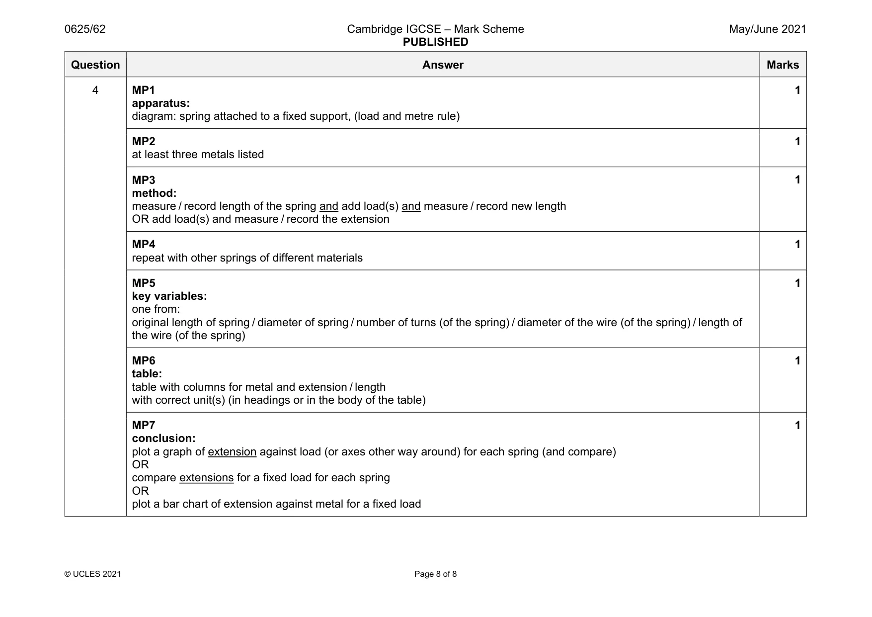
Mark scheme: 4 MP1 apparatus: diagram: spring attached to a fixed support, (load and metre rule) 1 MP2 at least three metals listed 1 MP3 method: measure / record length of the spring and add load(s) and measure / record new length OR add load(s) and measure / record the extension 1 MP4 repeat with other springs of different materials 1 MP5 key variables: one from: original length of spring / diameter of spring / number of turns (of the spring) / diameter of the wire (of the spring) / length of the wire (of the spring) 1 MP6 table: table with columns for metal and extension / length with correct unit(s) (in headings or in the body of the table) 1 MP7 conclusion: plot a graph of extension against load (or axes other way around) for each spring (and compare) OR compare extensions for a fixed load for each spring OR plot a bar chart of extension against metal for a fixed load 1
What was in this paper
The subtopics covered by these 4 questions, and how many questions each got. Open one in a new tab to see every Cambridge question on it.
What you needed in this session
Cambridge’s own grade thresholds for 2021 May/June, Paper 6 · Variant 2. A higher threshold means an easier paper — the bar moves with how the cohort did.