Cambridge A Level Physics 9702 — 2013 Oct/Nov Paper 4 · Variant 1
9702/41/O/N/13 · 12 questions · 100 marks · ≈113 min
The question paper and its mark scheme, free to read here and free to download. This is Cambridge’s own paper, exactly as it was sat.
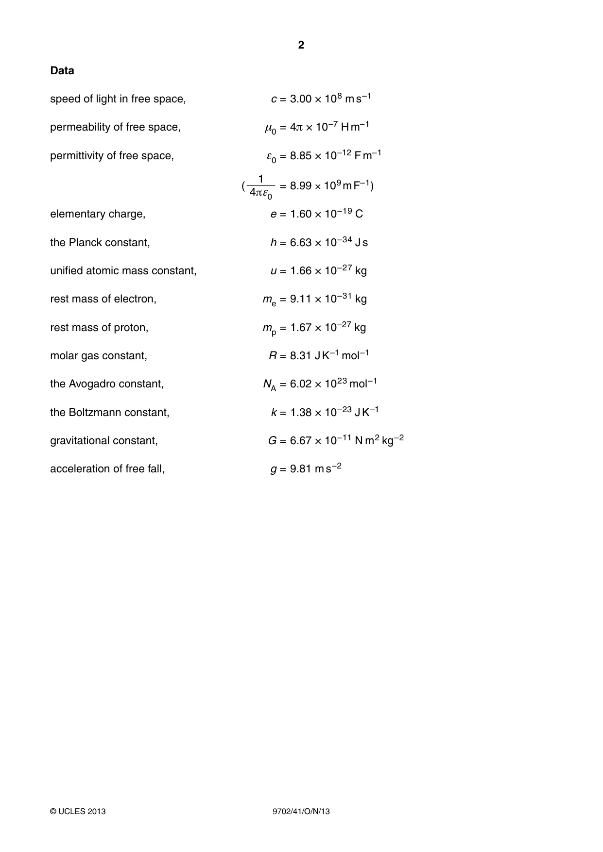
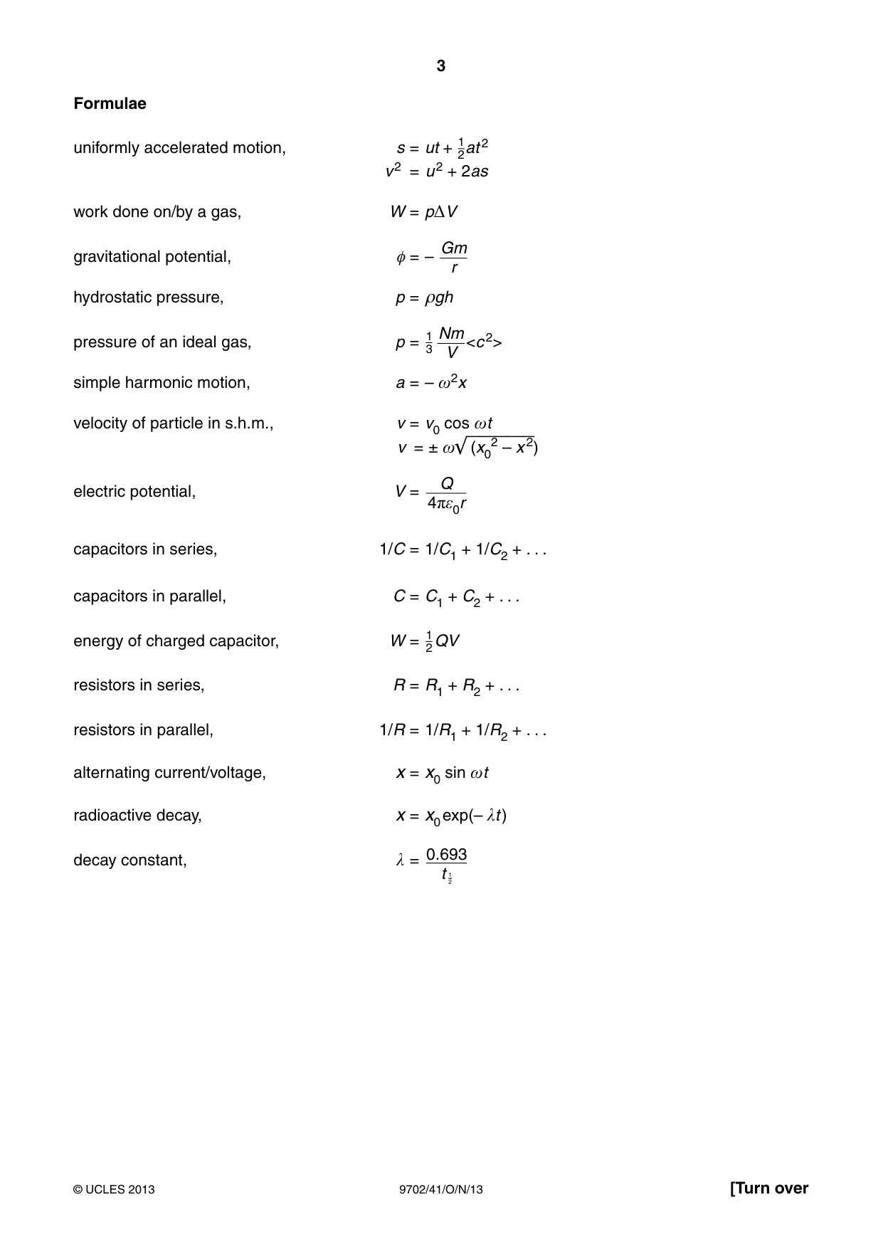
Question paper24 pages
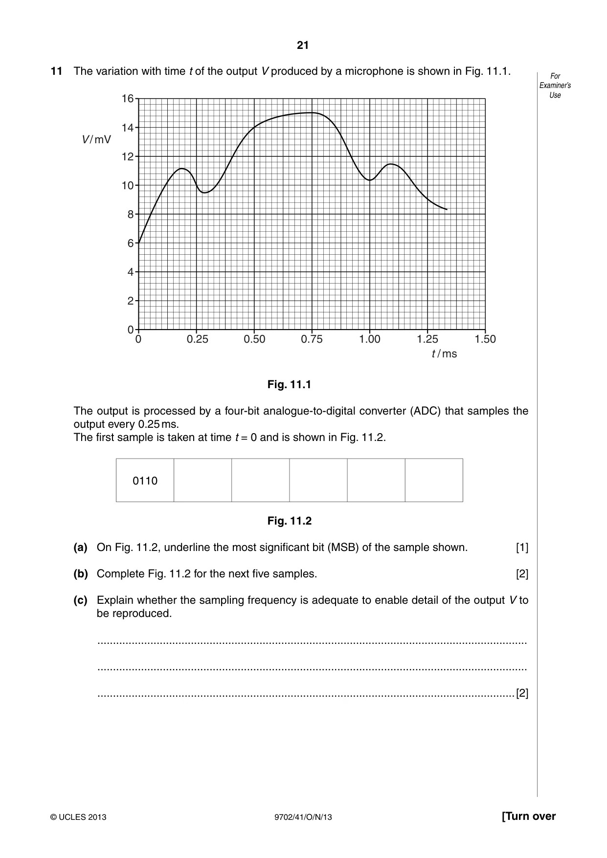
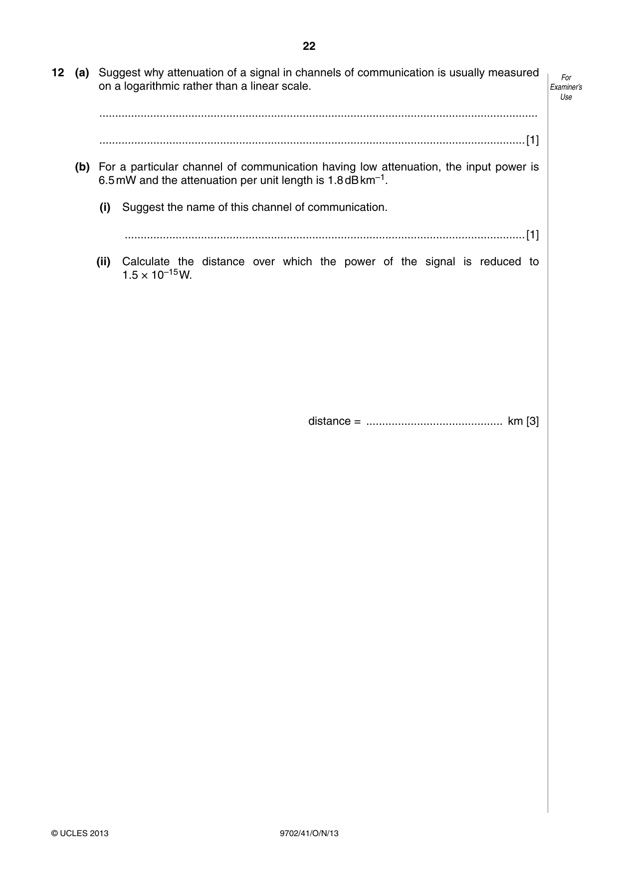


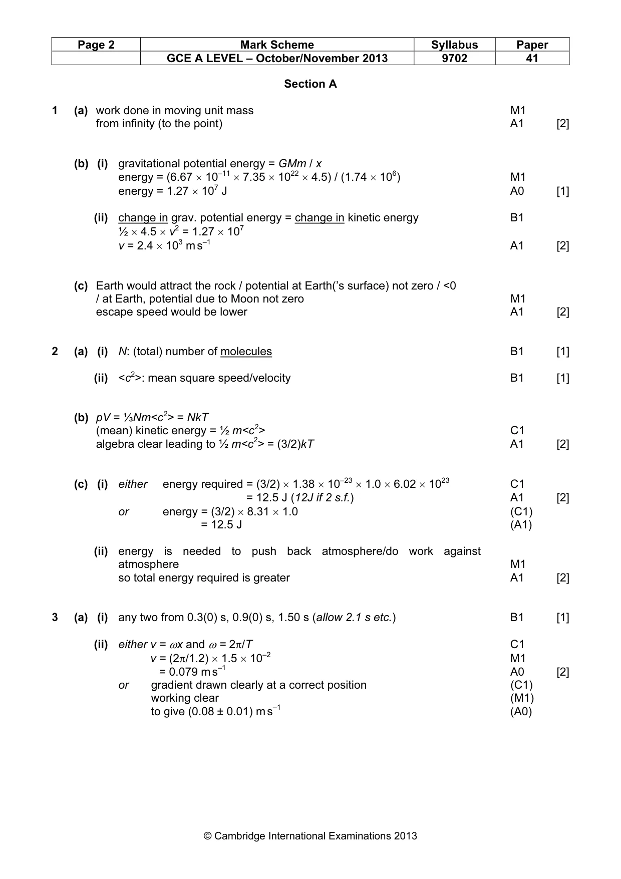
Mark scheme6 pages
Answers below. Sit the paper first if you are practising.
Questions as text
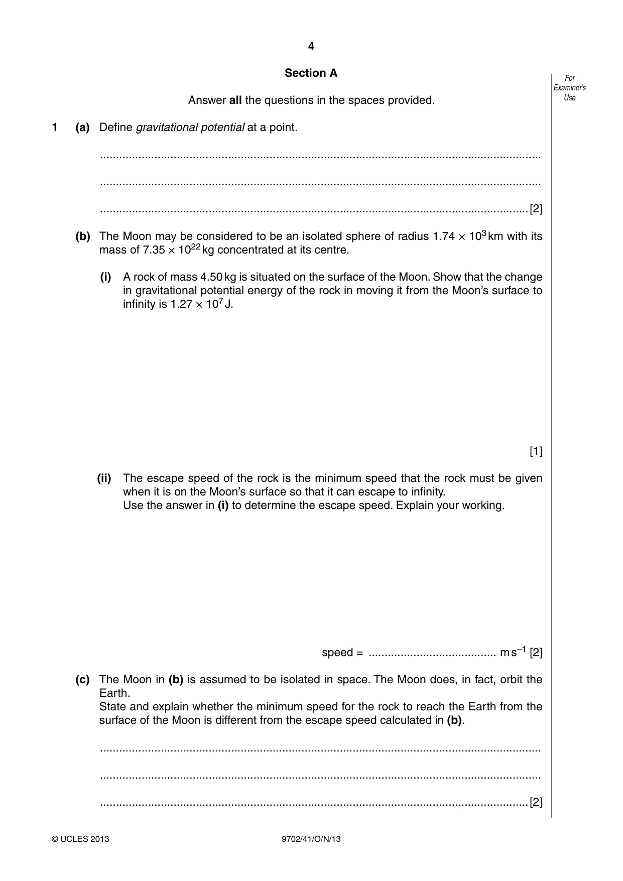
Q1 · Define gravitational potential at a point
1 (a) Define gravitational potential at a point. .......................................................................................................................................... .......................................................................................................................................... ......................................................................................................................................[2] (b) The Moon may be considered to be an isolated sphere of radius 1.74 × 10³ km with its mass of 7.35 × 10²² kg concentrated at its centre. (i) A rock of mass 4.50 kg is situated on the surface of the Moon. Show that the change in gravitational potential energy of the rock in moving it from the Moon’s surface to infinity is 1.27 × 10⁷ J. [1] (ii) The escape speed of the rock is the minimum speed that the rock must be given when it is on the Moon’s surface so that it can escape to infinity. Use the answer in (i) to determine the escape speed. Explain your working. speed = ........................................ m s–1 [2] (c) The Moon in (b) is assumed to be isolated in space. The Moon does, in fact, orbit the Earth. State and explain whether the minimum speed for the rock to reach the Earth from the surface of the Moon is different from the escape speed calculated in (b). .......................................................................................................................................... .......................................................................................................................................... ......................................................................................................................................[2]
Mark scheme: 1 (a) work done in moving unit mass M1 from infinity (to the point) A1 [2] (b) (i) gravitational potential energy = GMm / x energy = (6.67 × 10–11 × 7.35 × 1022 × 4.5) / (1.74 × 10⁶) M1 energy = 1.27 × 10⁷ J A0 [1] (ii) change in grav. potential energy = change in kinetic energy B1 ½ × 4.5 × v2 = 1.27 × 10⁷ v = 2.4 × 10³ m s–1 A1 [2] (c) Earth would attract the rock / potential at Earth(’s surface) not zero / <0 / at Earth, potential due to Moon not zero M1 escape speed would be lower A1 [2]
Q2 · The product of the pressure p and the volume V of an ideal gas is given by the expression…
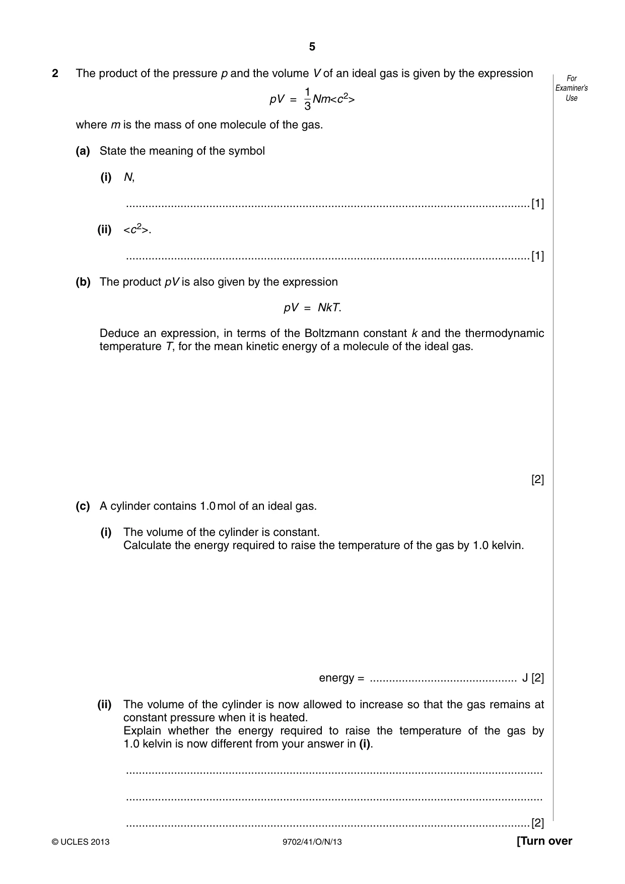
2 The product of the pressure p and the volume V of an ideal gas is given by the expression For 1 Examiner’s Use pV = 3Nm<c 2> where m is the mass of one molecule of the gas. (a) State the meaning of the symbol (i) N, ..............................................................................................................................[1] (ii) <c 2>. ..............................................................................................................................[1] (b) The product pV is also given by the expression pV = NkT. Deduce an expression, in terms of the Boltzmann constant k and the thermodynamic temperature T, for the mean kinetic energy of a molecule of the ideal gas. [2] (c) A cylinder contains 1.0 mol of an ideal gas. (i) The volume of the cylinder is constant. Calculate the energy required to raise the temperature of the gas by 1.0 kelvin. energy = .............................................. J [2] (ii) The volume of the cylinder is now allowed to increase so that the gas remains at constant pressure when it is heated. Explain whether the energy required to raise the temperature of the gas by 1.0 kelvin is now different from your answer in (i). .................................................................................................................................. .................................................................................................................................. ..............................................................................................................................[2]
Mark scheme: 2 (a) (i) N: (total) number of molecules B1 [1] (ii) <c2>: mean square speed/velocity B1 [1] (b) pV = ⅓Nm<c2> = NkT (mean) kinetic energy = ½ m<c2> C1 algebra clear leading to ½ m<c2> = (3/2)kT A1 [2] (c) (i) either energy required = (3/2) × 1.38 × 10–23 × 1.0 × 6.02 × 1023 C1 either energy required = 12.5 J (12J if 2 s.f.) A1 [2] or energy = (3/2) × 8.31 × 1.0 (C1) or energy = 12.5 J (A1) (ii) energy is needed to push back atmosphere/do work against atmosphere M1 so total energy required is greater A1 [2]
Q3 · A metal ball is suspended from a fixed point by means of a string, as illustrated in Fig
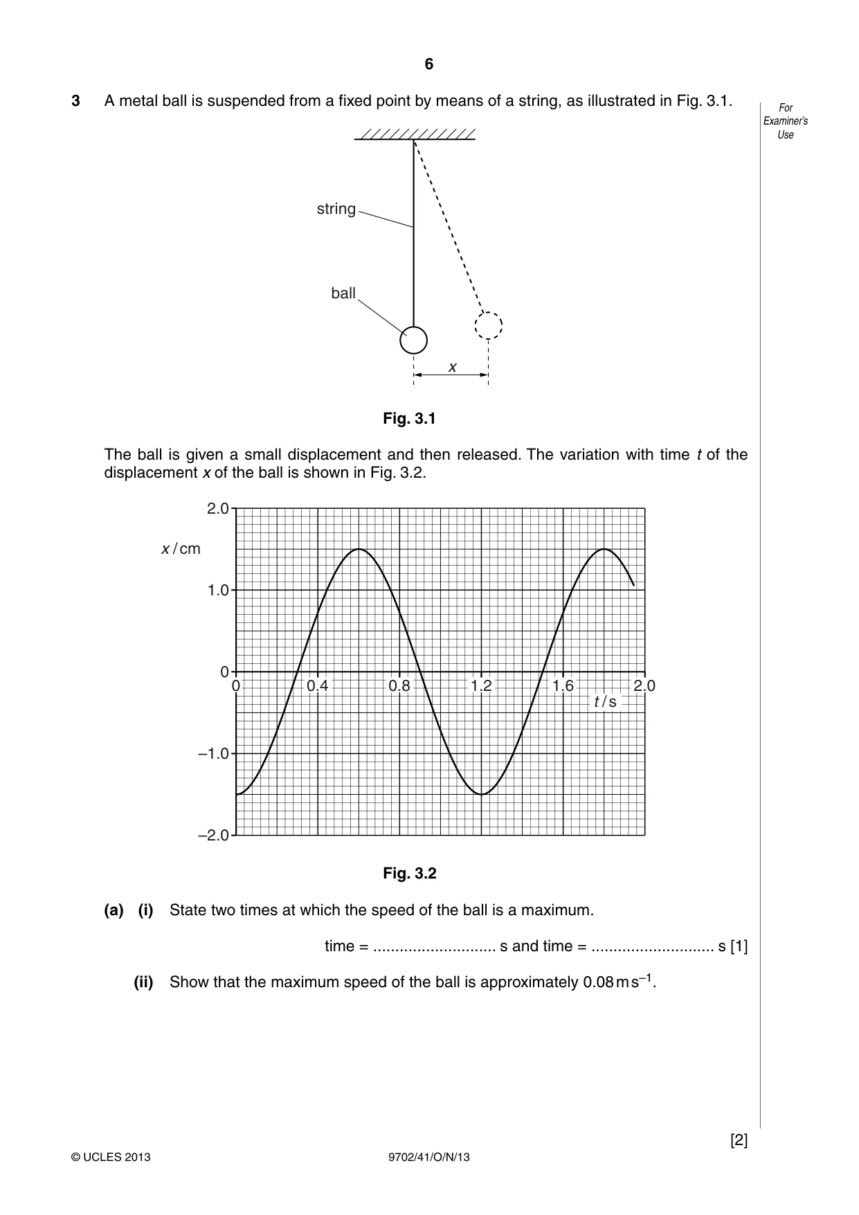
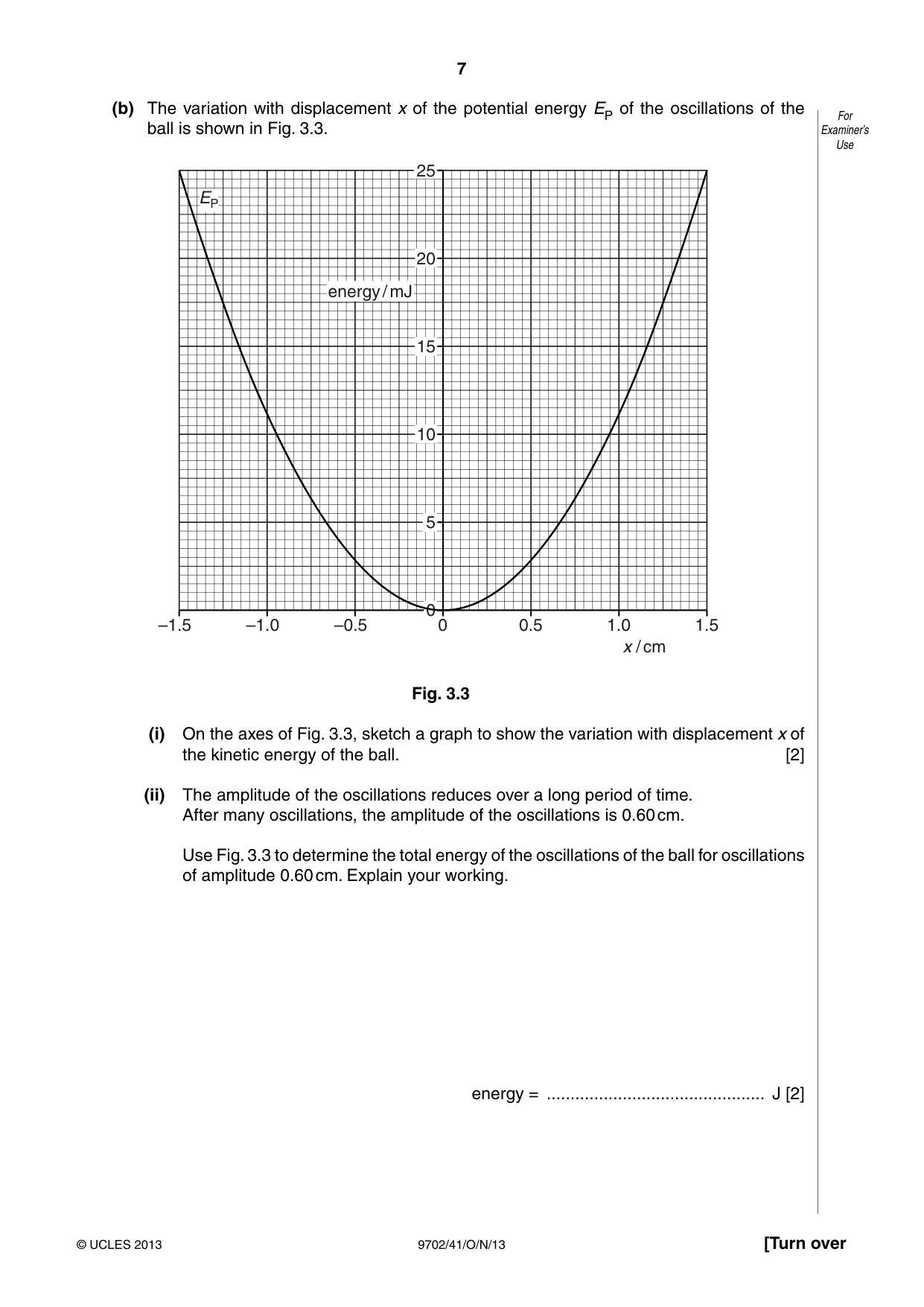
3 A metal ball is suspended from a fixed point by means of a string, as illustrated in Fig. 3.1. For Examiner’s Use string ball x Fig. 3.1 The ball is given a small displacement and then released. The variation with time t of the displacement x of the ball is shown in Fig. 3.2. 2.0 x / cm 1.0 0 0 0.4 0.8 1.2 1.6 2.0 t / s –1.0 –2.0 Fig. 3.2 (a) (i) State two times at which the speed of the ball is a maximum. time = ............................ s and time = ............................ s [1] (ii) Show that the maximum speed of the ball is approximately 0.08 m s–1. [2] (b) The variation with displacement x of the potential energy EP of the oscillations of the For ball is shown in Fig. 3.3. Examiner’s Use 25 EP 20 energy / mJ 15 10 5 0 –1.5 –1.0 –0.5 0 0.5 1.0 1.5 x / cm Fig. 3.3 (i) On the axes of Fig. 3.3, sketch a graph to show the variation with displacement x of the kinetic energy of the ball. [2] (ii) The amplitude of the oscillations reduces over a long period of time. After many oscillations, the amplitude of the oscillations is 0.60 cm. Use Fig. 3.3 to determine the total energy of the oscillations of the ball for oscillations of amplitude 0.60 cm. Explain your working. energy = .............................................. J [2]
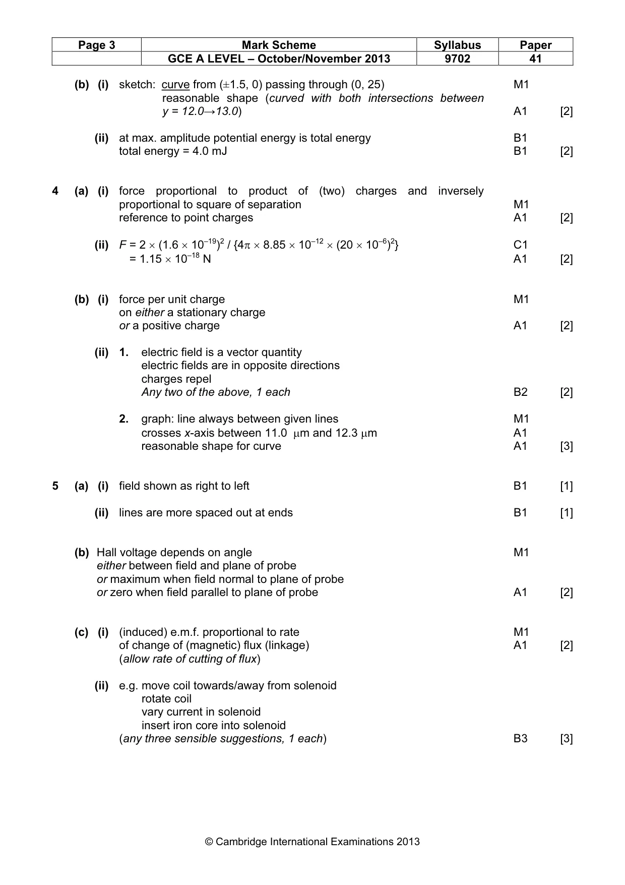
Mark scheme: 3 (a) (i) any two from 0.3(0) s, 0.9(0) s, 1.50 s (allow 2.1 s etc.) B1 [1] (ii) either v = ωx and ω = 2π/T C1 either v = (2π/1.2) × 1.5 × 10–2 M1 either v = 0.079 m s–1 A0 [2] or gradient drawn clearly at a correct position (C1) working clear (M1) to give (0.08 ± 0.01) m s–1 (A0) GCE A LEVEL – October/November 2013 9702 41 (b) (i) sketch: curve from (±1.5, 0) passing through (0, 25) M1 sketch: reasonable shape (curved with both intersections between y = 12.0→13.0) A1 [2] (ii) at max. amplitude potential energy is total energy B1 total energy = 4.0 mJ B1 [2]
Q4 · An α-particle and a proton are at rest a distance 20 μm apart in a vacuum, as illustrated…
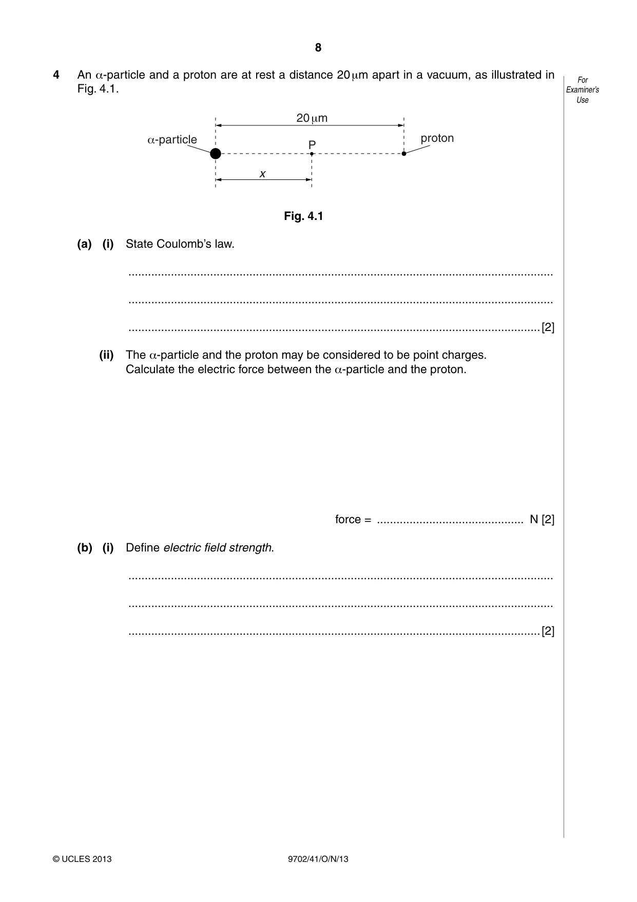
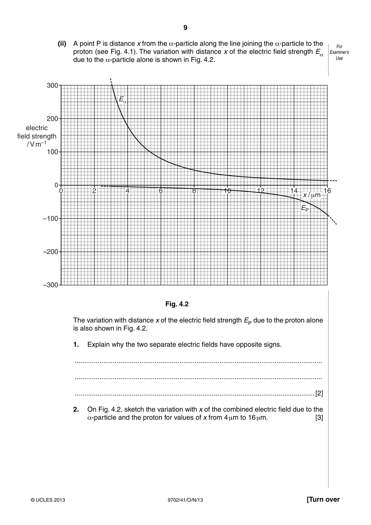
4 An α-particle and a proton are at rest a distance 20 μm apart in a vacuum, as illustrated in For Fig. 4.1. Examiner’s Use 20 +m _-particle proton P x Fig. 4.1 (a) (i) State Coulomb’s law. .................................................................................................................................. .................................................................................................................................. ..............................................................................................................................[2] (ii) The α-particle and the proton may be considered to be point charges. Calculate the electric force between the α-particle and the proton. force = ............................................. N [2] (b) (i) Define electric field strength. .................................................................................................................................. .................................................................................................................................. ..............................................................................................................................[2] (ii) A point P is distance x from the α-particle along the line joining the α-particle to the For Examiner’s proton (see Fig. 4.1). The variation with distance x of the electric field strength Eα due to the α-particle alone is shown in Fig. 4.2. Use 300 E_ 200 electric field strength / V m–1 100 0 0 2 4 6 8 10 12 14 16 x / +m EP –100 –200 –300 Fig. 4.2 The variation with distance x of the electric field strength EP due to the proton alone is also shown in Fig. 4.2. 1. Explain why the two separate electric fields have opposite signs. .................................................................................................................................. .................................................................................................................................. ..............................................................................................................................[2] 2. On Fig. 4.2, sketch the variation with x of the combined electric field due to the α-particle and the proton for values of x from 4 μm to 16 μm. [3]
Mark scheme: 4 (a) (i) force proportional to product of (two) charges and inversely proportional to square of separation M1 reference to point charges A1 [2] (ii) F = 2 × (1.6 × 10–19)2 / {4π × 8.85 × 10–12 × (20 × 10–6)2} C1 F = 1.15 × 10⁻¹⁸ N A1 [2] (b) (i) force per unit charge M1 on either a stationary charge or a positive charge A1 [2] (ii) 1. electric field is a vector quantity electric fields are in opposite directions charges repel Any two of the above, 1 each B2 [2] 2. graph: line always between given lines M1 crosses x-axis between 11.0 µm and 12.3 µm A1 reasonable shape for curve A1 [3]
Q5 · An incomplete diagram for the magnetic flux pattern due to a current-carrying solenoid…
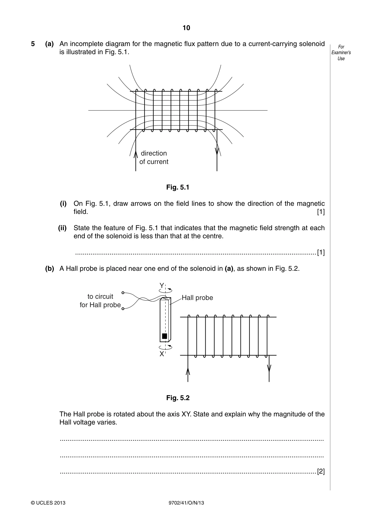
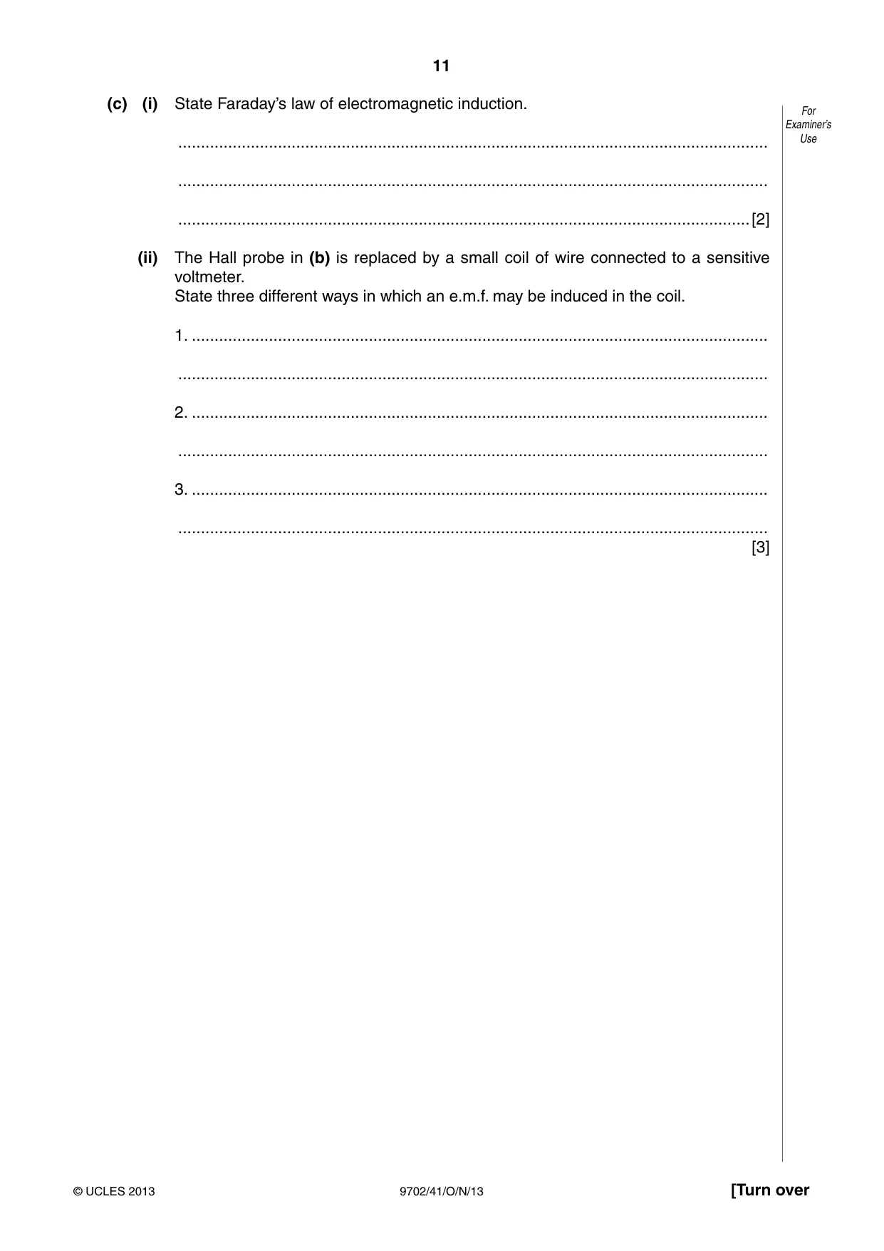
5 (a) An incomplete diagram for the magnetic flux pattern due to a current-carrying solenoid For is illustrated in Fig. 5.1. Examiner’s Use direction of current Fig. 5.1 (i) On Fig. 5.1, draw arrows on the field lines to show the direction of the magnetic field. [1] (ii) State the feature of Fig. 5.1 that indicates that the magnetic field strength at each end of the solenoid is less than that at the centre. ..............................................................................................................................[1] (b) A Hall probe is placed near one end of the solenoid in (a), as shown in Fig. 5.2. Y to circuit Hall probe for Hall probe X Fig. 5.2 The Hall probe is rotated about the axis XY. State and explain why the magnitude of the Hall voltage varies. .......................................................................................................................................... .......................................................................................................................................... ......................................................................................................................................[2] (c) (i) State Faraday’s law of electromagnetic induction. For Examiner’s .................................................................................................................................. Use .................................................................................................................................. ..............................................................................................................................[2] (ii) The Hall probe in (b) is replaced by a small coil of wire connected to a sensitive voltmeter. State three different ways in which an e.m.f. may be induced in the coil. 1. ............................................................................................................................... .................................................................................................................................. 2. ............................................................................................................................... .................................................................................................................................. 3. ............................................................................................................................... .................................................................................................................................. [3]
Mark scheme: 5 (a) (i) field shown as right to left B1 [1] (ii) lines are more spaced out at ends B1 [1] (b) Hall voltage depends on angle M1 either between field and plane of probe or maximum when field normal to plane of probe or zero when field parallel to plane of probe A1 [2] (c) (i) (induced) e.m.f. proportional to rate M1 of change of (magnetic) flux (linkage) A1 [2] (allow rate of cutting of flux) (ii) e.g. move coil towards/away from solenoid e.g. rotate coil e.g. vary current in solenoid e.g. insert iron core into solenoid (any three sensible suggestions, 1 each) B3 [3] GCE A LEVEL – October/November 2013 9702 41
Q6 · A charged particle of mass m and charge –q is travelling through a vacuum at constant For…
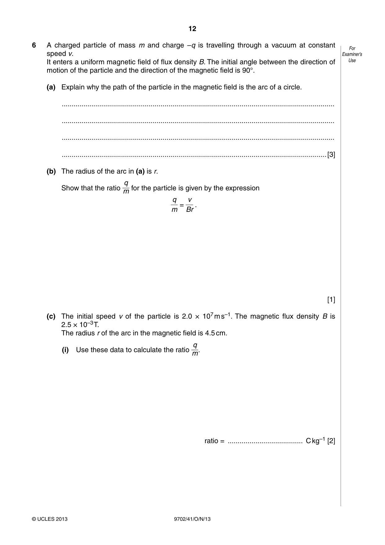
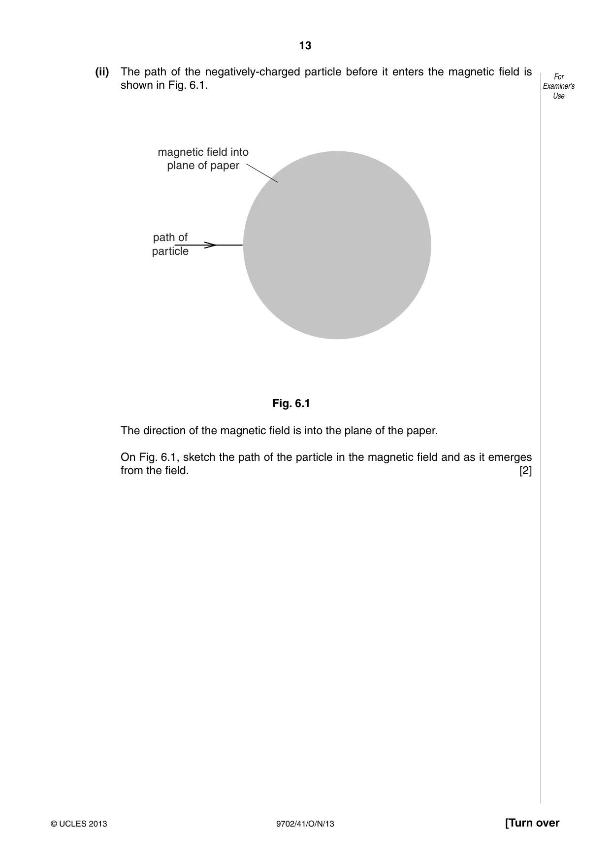
6 A charged particle of mass m and charge –q is travelling through a vacuum at constant For speed v. Examiner’s It enters a uniform magnetic field of flux density B. The initial angle between the direction of Use motion of the particle and the direction of the magnetic field is 90°. (a) Explain why the path of the particle in the magnetic field is the arc of a circle. .......................................................................................................................................... .......................................................................................................................................... .......................................................................................................................................... ......................................................................................................................................[3] (b) The radius of the arc in (a) is r. q Show that the ratio for the particle is given by the expression m q v = . m Br [1] (c) The initial speed v of the particle is 2.0 × 10⁷ m s–1. The magnetic flux density B is 2.5 × 10⁻³ T. The radius r of the arc in the magnetic field is 4.5 cm. q (i) Use these data to calculate the ratio m. ratio = ...................................... C kg–1 [2] (ii) The path of the negatively-charged particle before it enters the magnetic field is For shown in Fig. 6.1. Examiner’s Use magnetic field into plane of paper path of particle Fig. 6.1 The direction of the magnetic field is into the plane of the paper. On Fig. 6.1, sketch the path of the particle in the magnetic field and as it emerges from the field. [2]
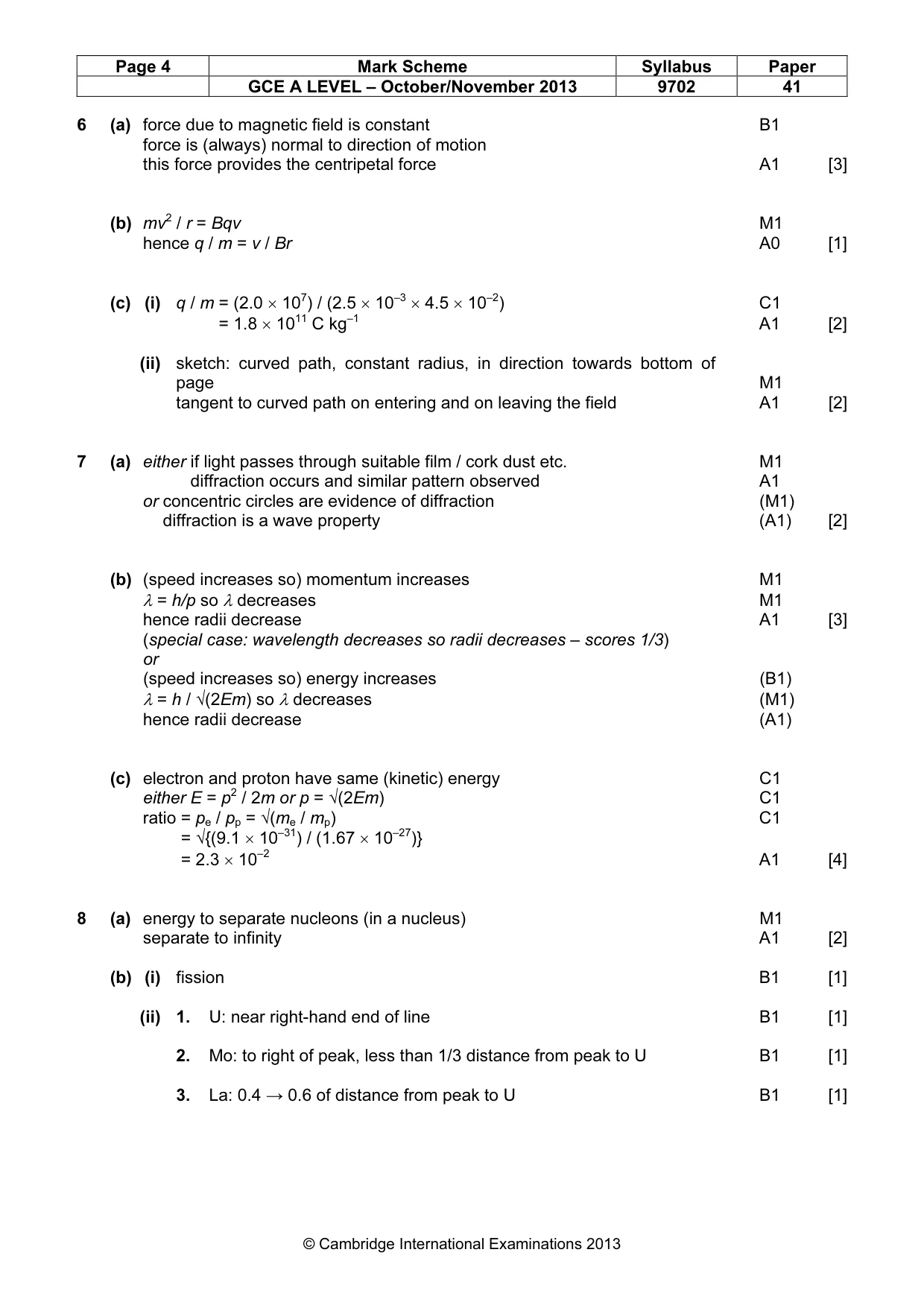
Mark scheme: 6 (a) force due to magnetic field is constant B1 force is (always) normal to direction of motion this force provides the centripetal force A1 [3] (b) mv2 / r = Bqv M1 hence q / m = v / Br A0 [1] (c) (i) q / m = (2.0 × 10⁷) / (2.5 × 10–3 × 4.5 × 10–2) C1 q / m = 1.8 × 10¹¹ C kg–1 A1 [2] (ii) sketch: curved path, constant radius, in direction towards bottom of page M1 tangent to curved path on entering and on leaving the field A1 [2]
Q7 · Electrons, travelling at speed v in a vacuum, are incident on a very thin carbon film, as…
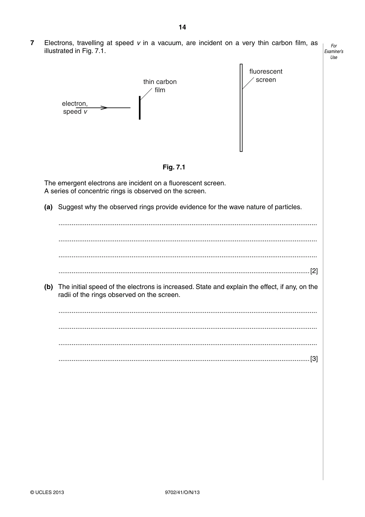
7 Electrons, travelling at speed v in a vacuum, are incident on a very thin carbon film, as For illustrated in Fig. 7.1. Examiner’s Use fluorescent screen thin carbon film electron, speed v Fig. 7.1 The emergent electrons are incident on a fluorescent screen. A series of concentric rings is observed on the screen. (a) Suggest why the observed rings provide evidence for the wave nature of particles. .......................................................................................................................................... .......................................................................................................................................... .......................................................................................................................................... ......................................................................................................................................[2] (b) The initial speed of the electrons is increased. State and explain the effect, if any, on the radii of the rings observed on the screen. .......................................................................................................................................... .......................................................................................................................................... .......................................................................................................................................... ......................................................................................................................................[3] (c) A proton and an electron are each accelerated from rest through the same potential For difference. Examiner’s Determine the ratio Use de Broglie wavelength of the proton . de Broglie wavelength of the electron ratio = ..................................................[4]
Mark scheme: 7 (a) either if light passes through suitable film / cork dust etc. M1 either diffraction occurs and similar pattern observed A1 or concentric circles are evidence of diffraction (M1) or diffraction is a wave property (A1) [2] (b) (speed increases so) momentum increases M1 λ = h/p so λ decreases M1 hence radii decrease A1 [3] (special case: wavelength decreases so radii decreases – scores 1/3) or (speed increases so) energy increases (B1) λ = h / √(2Em) so λ decreases (M1) hence radii decrease (A1) (c) electron and proton have same (kinetic) energy C1 either E = p2 / 2m or p = √(2Em) C1 ratio = pe / pp = √(me / mp) C1 ratio = √{(9.1 × 10⁻³¹) / (1.67 × 10⁻²⁷)} ratio = 2.3 × 10⁻² A1 [4]
Q8 · State what is meant by nuclear binding energy
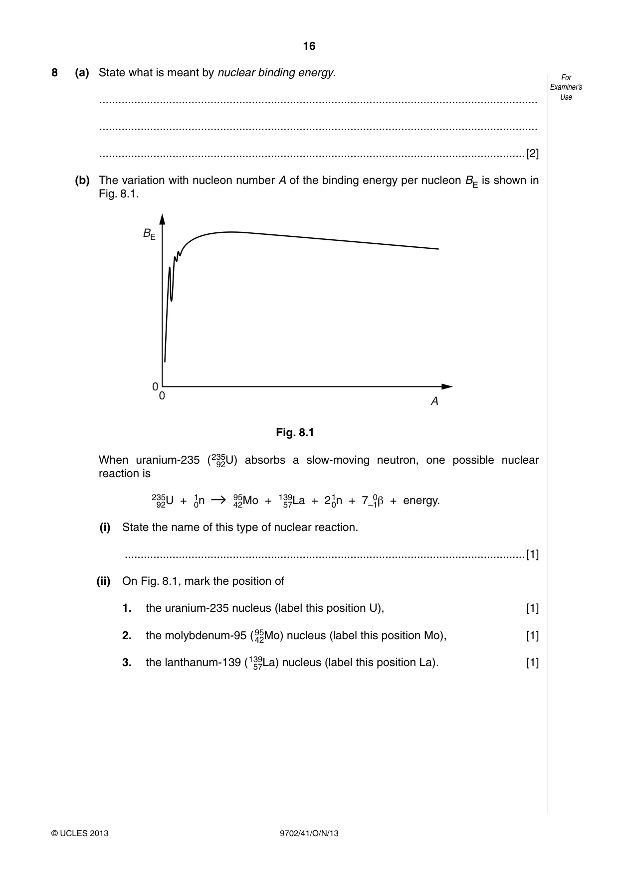
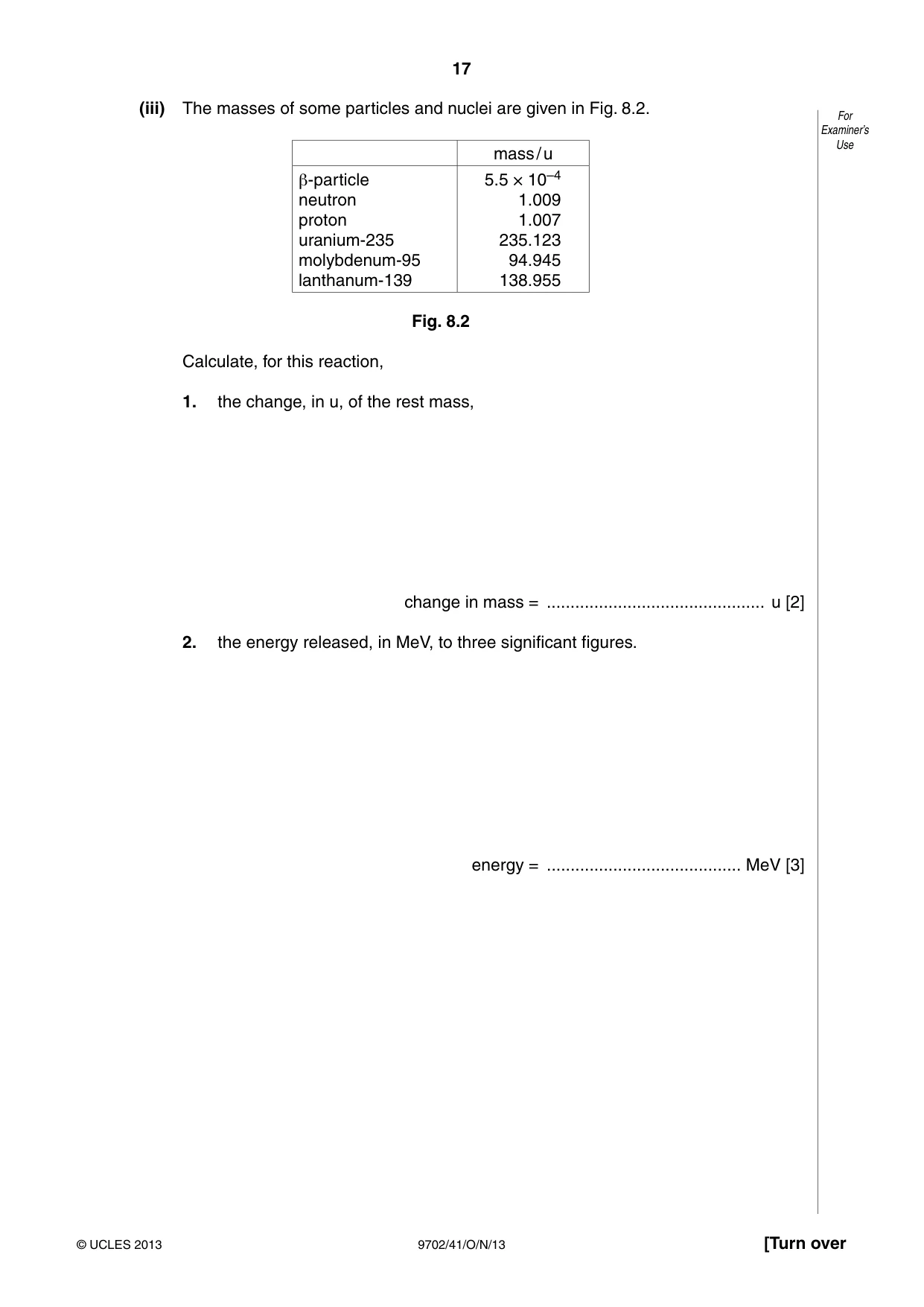
8 (a) State what is meant by nuclear binding energy. For Examiner’s .......................................................................................................................................... Use .......................................................................................................................................... ......................................................................................................................................[2] (b) The variation with nucleon number A of the binding energy per nucleon BE is shown in Fig. 8.1. BE 0 0 A Fig. 8.1 When uranium-235 (23592U) absorbs a slow-moving neutron, one possible nuclear reaction is 23592U + 10n 9542Mo + 13957La + 210n + 7 –1β0 + energy. (i) State the name of this type of nuclear reaction. ..............................................................................................................................[1] (ii) On Fig. 8.1, mark the position of 1. the uranium-235 nucleus (label this position U), [1] 2. the molybdenum-95 (9542Mo) nucleus (label this position Mo), [1] 3. the lanthanum-139 (13957La) nucleus (label this position La). [1] (iii) The masses of some particles and nuclei are given in Fig. 8.2. For Examiner’s Use mass / u β-particle 5.5 × 10⁻⁴ neutron 1.009 proton 1.007 uranium-235 235.123 molybdenum-95 94.945 lanthanum-139 138.955 Fig. 8.2 Calculate, for this reaction, 1. the change, in u, of the rest mass, change in mass = .............................................. u [2] 2. the energy released, in MeV, to three significant figures. energy = ......................................... MeV [3]
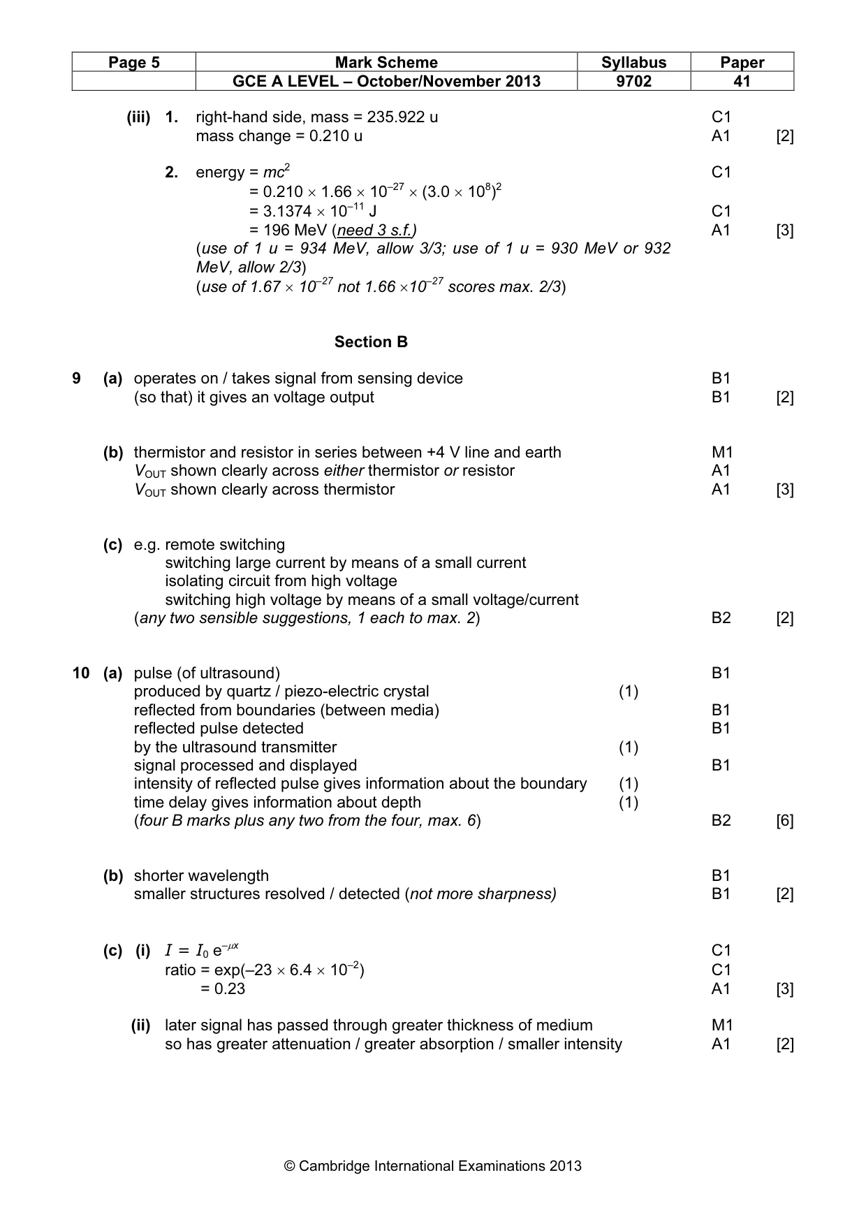
Mark scheme: 8 (a) energy to separate nucleons (in a nucleus) M1 separate to infinity A1 [2] (b) (i) fission B1 [1] (ii) 1. U: near right-hand end of line B1 [1] 2. Mo: to right of peak, less than 1/3 distance from peak to U B1 [1] 3. La: 0.4 → 0.6 of distance from peak to U B1 [1] GCE A LEVEL – October/November 2013 9702 41 (iii) 1. right-hand side, mass = 235.922 u C1 mass change = 0.210 u A1 [2] 2. energy = mc2 C1 energy = 0.210 × 1.66 × 10–27 × (3.0 × 108)2 energy = 3.1374 × 10⁻¹¹ J C1 energy = 196 MeV (need 3 s.f.) A1 [3] (use of 1 u = 934 MeV, allow 3/3; use of 1 u = 930 MeV or 932 MeV, allow 2/3) (use of 1.67 × 10⁻²⁷ not 1.66 ×10⁻²⁷ scores max. 2/3) Section B
Q9 · An electronic sensor may be represented by the block diagram of Fig
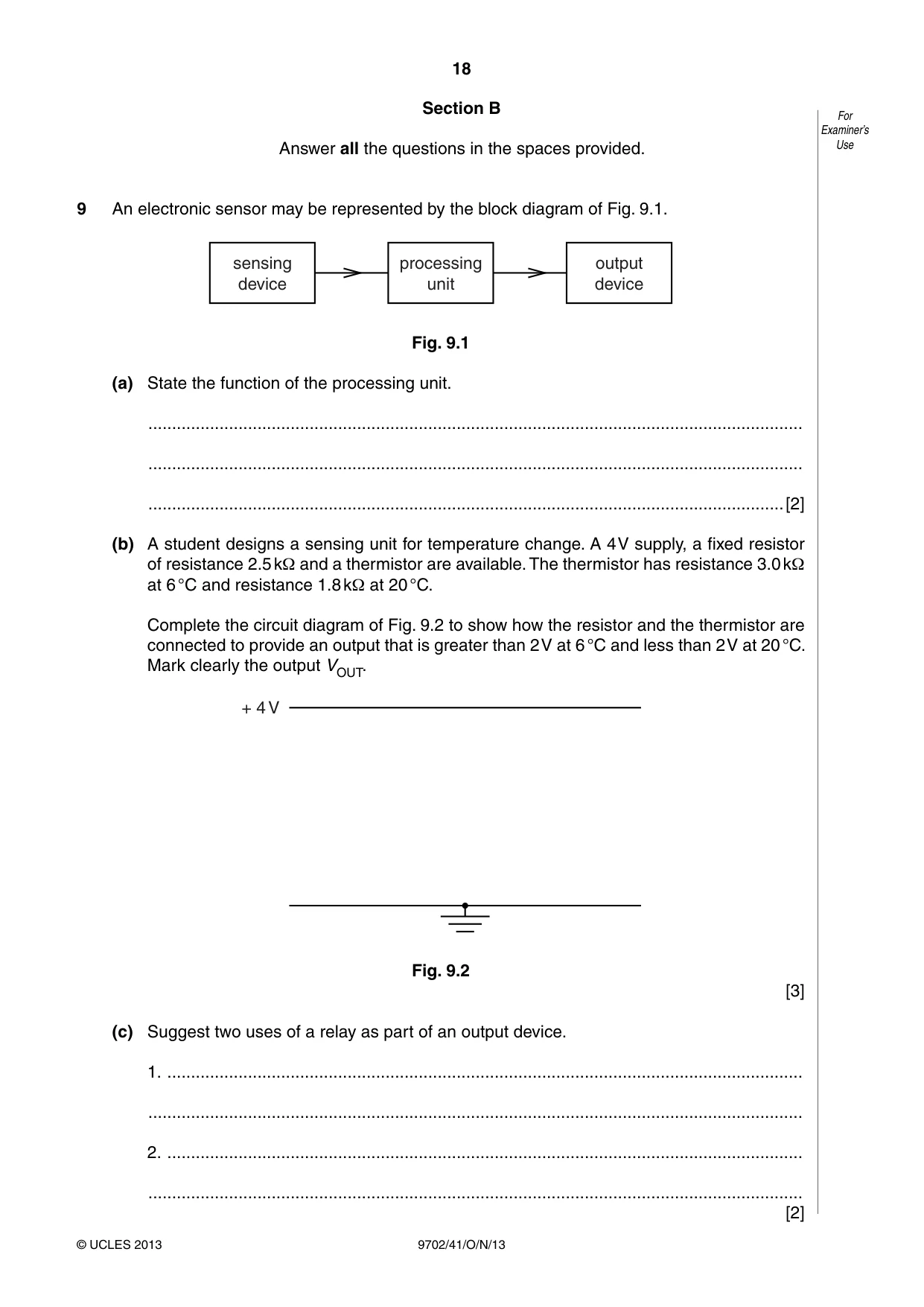
9 An electronic sensor may be represented by the block diagram of Fig. 9.1. sensing processing output device unit device Fig. 9.1 (a) State the function of the processing unit. .......................................................................................................................................... .......................................................................................................................................... ......................................................................................................................................[2] (b) A student designs a sensing unit for temperature change. A 4 V supply, a fixed resistor of resistance 2.5 kΩ and a thermistor are available. The thermistor has resistance 3.0 kΩ at 6 °C and resistance 1.8 kΩ at 20 °C. Complete the circuit diagram of Fig. 9.2 to show how the resistor and the thermistor are connected to provide an output that is greater than 2 V at 6 °C and less than 2 V at 20 °C. Mark clearly the output VOUT. + 4 V Fig. 9.2 [3] (c) Suggest two uses of a relay as part of an output device. 1. ...................................................................................................................................... .......................................................................................................................................... 2. ...................................................................................................................................... .......................................................................................................................................... [2]
Mark scheme: 9 (a) operates on / takes signal from sensing device B1 (so that) it gives an voltage output B1 [2] (b) thermistor and resistor in series between +4 V line and earth M1 VOUT shown clearly across either thermistor or resistor A1 VOUT shown clearly across thermistor A1 [3] (c) e.g. remote switching e.g. switching large current by means of a small current e.g. isolating circuit from high voltage e.g. switching high voltage by means of a small voltage/current (any two sensible suggestions, 1 each to max. 2) B2 [2]
Q10 · Explain the main principles behind the use of ultrasound to obtain diagnostic information…
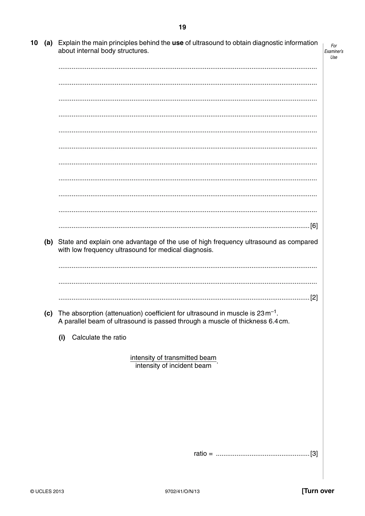
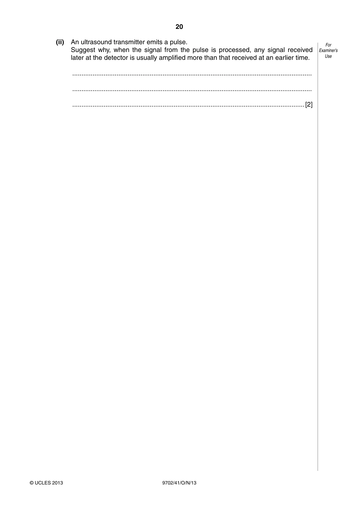
10 (a) Explain the main principles behind the use of ultrasound to obtain diagnostic information For about internal body structures. Examiner’s Use .......................................................................................................................................... .......................................................................................................................................... .......................................................................................................................................... .......................................................................................................................................... .......................................................................................................................................... .......................................................................................................................................... .......................................................................................................................................... .......................................................................................................................................... .......................................................................................................................................... .......................................................................................................................................... ......................................................................................................................................[6] (b) State and explain one advantage of the use of high frequency ultrasound as compared with low frequency ultrasound for medical diagnosis. .......................................................................................................................................... .......................................................................................................................................... ......................................................................................................................................[2] (c) The absorption (attenuation) coefficient for ultrasound in muscle is 23 m–1. A parallel beam of ultrasound is passed through a muscle of thickness 6.4 cm. (i) Calculate the ratio intensity of transmitted beam . intensity of incident beam ratio = ..................................................[3] (ii) An ultrasound transmitter emits a pulse. For Suggest why, when the signal from the pulse is processed, any signal received Examiner’s later at the detector is usually amplified more than that received at an earlier time. Use .................................................................................................................................. .................................................................................................................................. ..............................................................................................................................[2]
Mark scheme: 10 (a) pulse (of ultrasound) B1 produced by quartz / piezo-electric crystal (1) reflected from boundaries (between media) B1 reflected pulse detected B1 by the ultrasound transmitter (1) signal processed and displayed B1 intensity of reflected pulse gives information about the boundary (1) time delay gives information about depth (1) (four B marks plus any two from the four, max. 6) B2 [6] (b) shorter wavelength B1 smaller structures resolved / detected (not more sharpness) B1 [2] (c) (i) I = I0 e–µx C1 ratio = exp(–23 × 6.4 × 10–2) C1 ratio = 0.23 A1 [3] (ii) later signal has passed through greater thickness of medium M1 so has greater attenuation / greater absorption / smaller intensity A1 [2] GCE A LEVEL – October/November 2013 9702 41
Q11 · The variation with time t of the output V produced by a microphone is shown in Fig
11 The variation with time t of the output V produced by a microphone is shown in Fig. 11.1. For Examiner’s 16 Use 14 V / mV 12 10 8 6 4 2 0 0 0.25 0.50 0.75 1.00 1.25 1.50 t / ms Fig. 11.1 The output is processed by a four-bit analogue-to-digital converter (ADC) that samples the output every 0.25 ms. The first sample is taken at time t = 0 and is shown in Fig. 11.2. 0110 Fig. 11.2 (a) On Fig. 11.2, underline the most significant bit (MSB) of the sample shown. [1] (b) Complete Fig. 11.2 for the next five samples. [2] (c) Explain whether the sampling frequency is adequate to enable detail of the output V to be reproduced. .......................................................................................................................................... .......................................................................................................................................... ......................................................................................................................................[2]
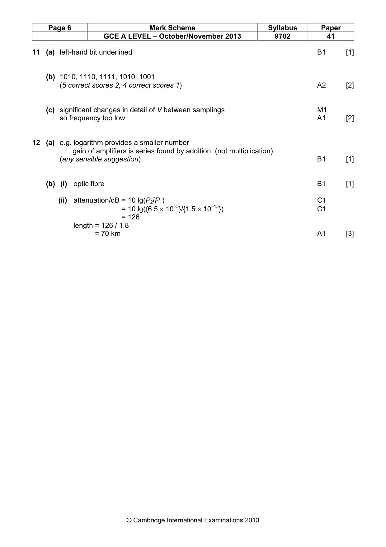
Mark scheme: 11 (a) left-hand bit underlined B1 [1] (b) 1010, 1110, 1111, 1010, 1001 (5 correct scores 2, 4 correct scores 1) A2 [2] (c) significant changes in detail of V between samplings M1 so frequency too low A1 [2]
Q12 · Suggest why attenuation of a signal in channels of communication is usually measured For…
12 (a) Suggest why attenuation of a signal in channels of communication is usually measured For on a logarithmic rather than a linear scale. Examiner’s Use .......................................................................................................................................... ......................................................................................................................................[1] (b) For a particular channel of communication having low attenuation, the input power is 6.5 mW and the attenuation per unit length is 1.8 dB km–1. (i) Suggest the name of this channel of communication. ..............................................................................................................................[1] (ii) Calculate the distance over which the power of the signal is reduced to 1.5 × 10⁻¹⁵ W. distance = ........................................... km [3]
Mark scheme: 12 (a) e.g. logarithm provides a smaller number e.g. gain of amplifiers is series found by addition, (not multiplication) (any sensible suggestion) B1 [1] (b) (i) optic fibre B1 [1] (ii) attenuation/dB = 10 lg(P2/P1) C1 attenuation/dB = 10 lg({6.5 × 10⁻³}/{1.5 × 10–15}) C1 attenuation/dB = 126 length = 126 / 1.8 length = 70 km A1 [3]
What was in this paper
The subtopics covered by these 12 questions, and how many questions each got. Open one in a new tab to see every Cambridge question on it.
1Electric force between point charges1Electromagnetic induction1Electromagnetic spectrum1Energy in simple harmonic motion1Force on a moving charge1Gravitational field of a point mass1Kinetic theory of gases1Potential dividers1Production and use of ultrasound1Radioactive decay1Wave-particle duality1What you needed in this session
Cambridge’s own grade thresholds for 2013 Oct/Nov, Paper 4 · Variant 1. A higher threshold means an easier paper — the bar moves with how the cohort did.