Cambridge A Level Physics 9702 — 2008 May/June Paper 4 · Variant 1
9702/41/M/J/08 · 12 questions · 100 marks · ≈113 min
The question paper and its mark scheme, free to read here and free to download. This is Cambridge’s own paper, exactly as it was sat.
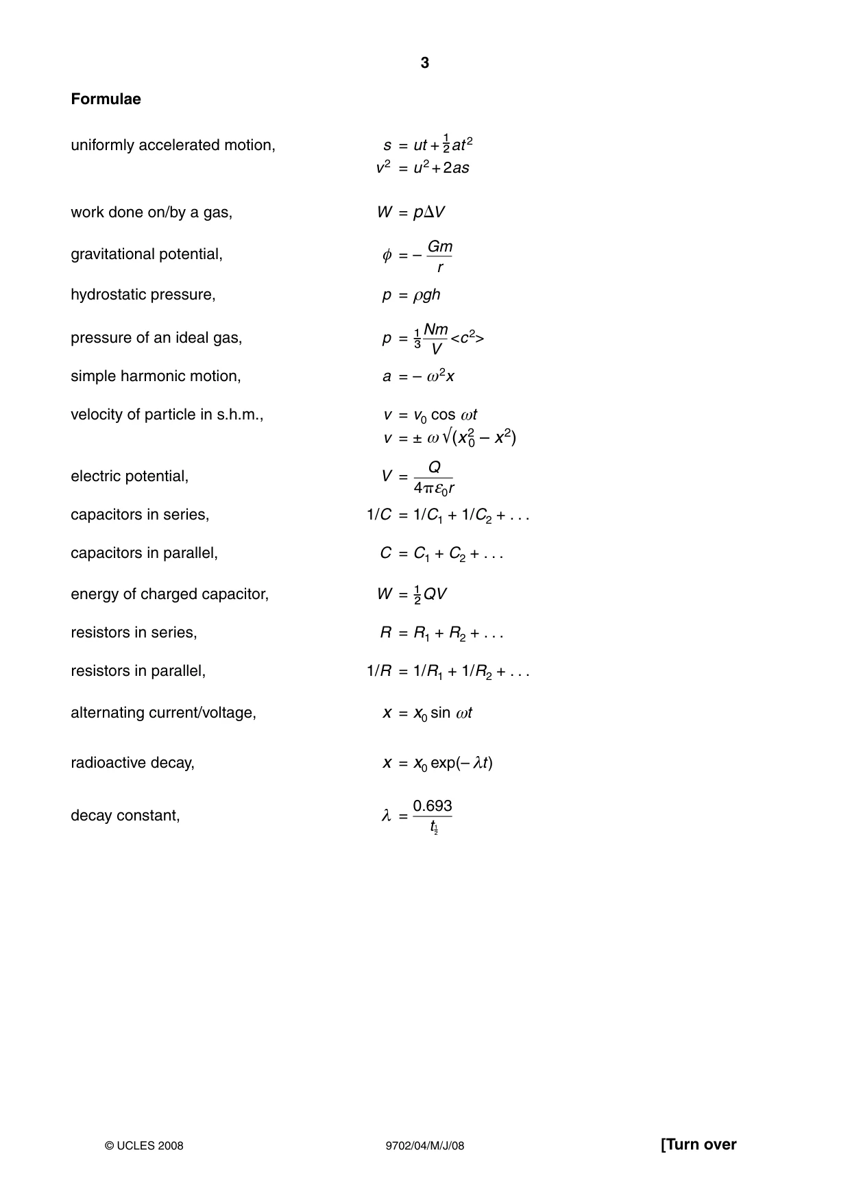
Question paper24 pages

Mark scheme5 pages
Answers below. Sit the paper first if you are practising.
Questions as text
Question 1
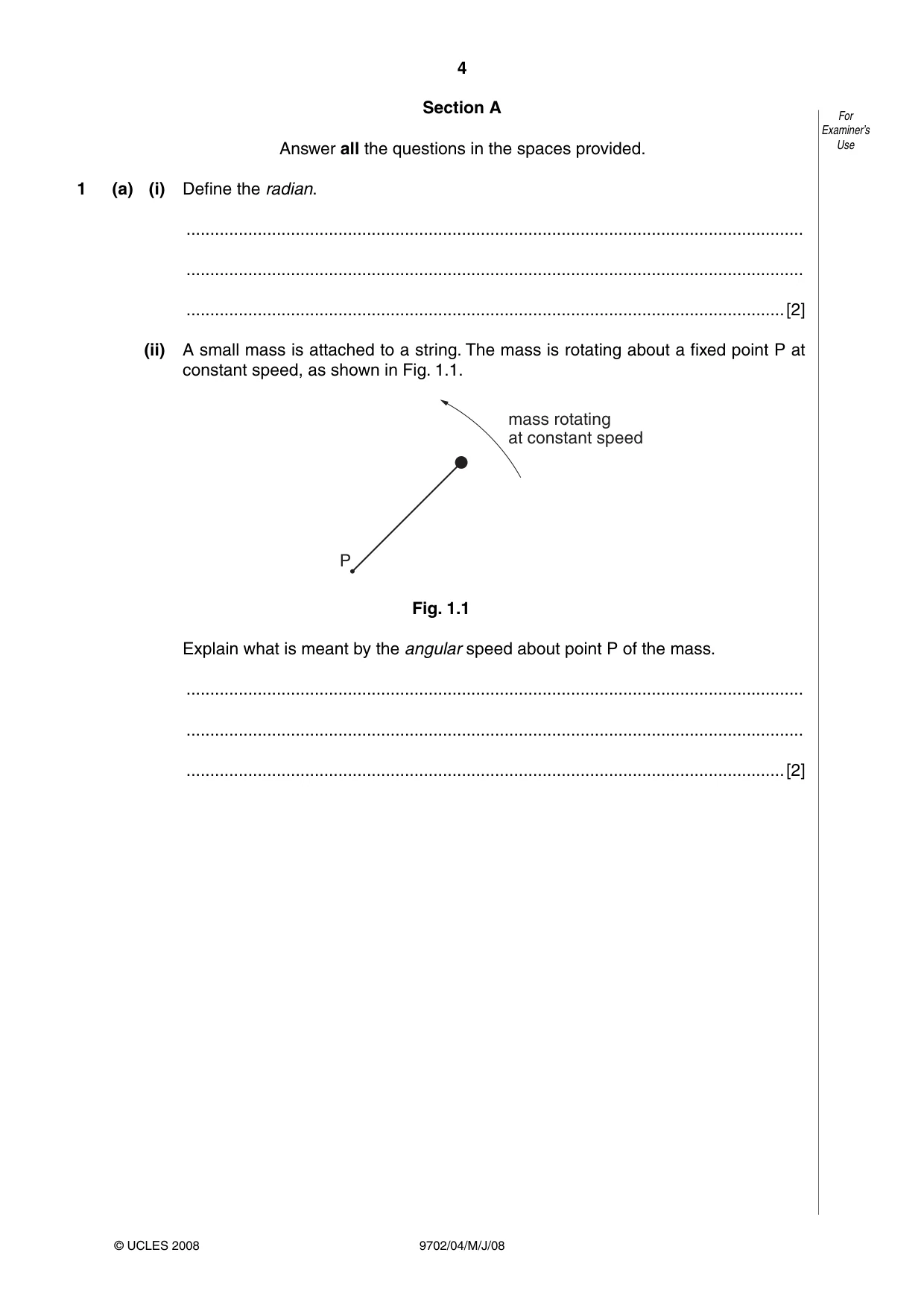
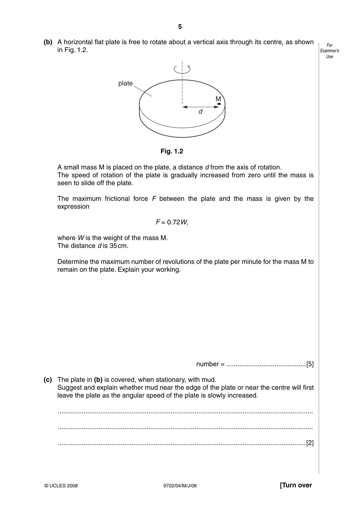
1 (a) (i) Define the radian. .................................................................................................................................. .................................................................................................................................. ..............................................................................................................................[2] (ii) A small mass is attached to a string. The mass is rotating about a fixed point P at constant speed, as shown in Fig. 1.1. mass rotating at constant speed P Fig. 1.1 Explain what is meant by the angular speed about point P of the mass. .................................................................................................................................. .................................................................................................................................. ..............................................................................................................................[2] (b) A horizontal flat plate is free to rotate about a vertical axis through its centre, as shown For in Fig. 1.2. Examiner’s Use plate M d Fig. 1.2 A small mass M is placed on the plate, a distance d from the axis of rotation. The speed of rotation of the plate is gradually increased from zero until the mass is seen to slide off the plate. The maximum frictional force F between the plate and the mass is given by the expression F = 0.72W, where W is the weight of the mass M. The distance d is 35 cm. Determine the maximum number of revolutions of the plate per minute for the mass M to remain on the plate. Explain your working. number = ........................................... [5] (c) The plate in (b) is covered, when stationary, with mud. Suggest and explain whether mud near the edge of the plate or near the centre will first leave the plate as the angular speed of the plate is slowly increased. .......................................................................................................................................... .......................................................................................................................................... ......................................................................................................................................[2]
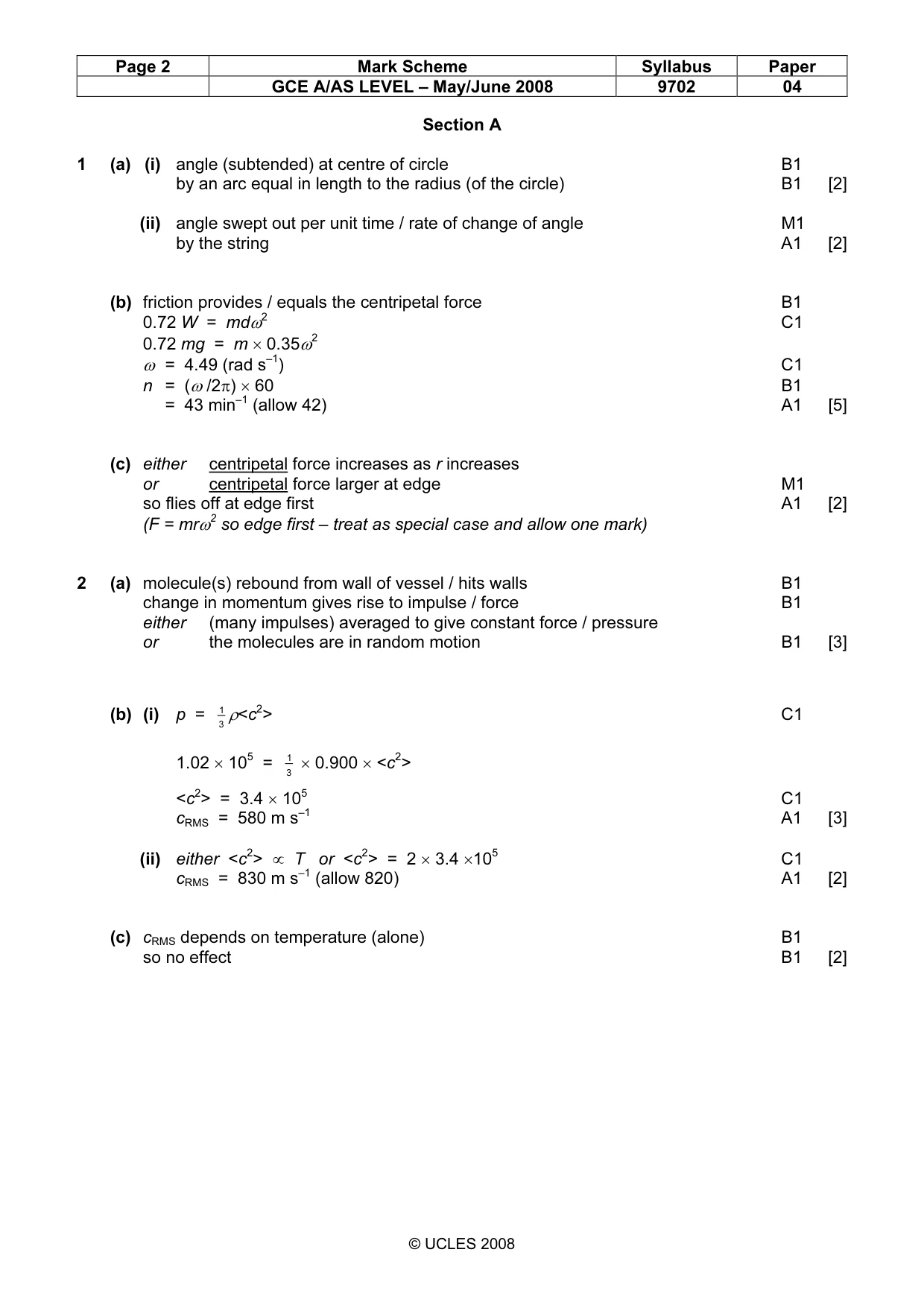
Mark scheme: 1 (a) (i) angle (subtended) at centre of circle B1 by an arc equal in length to the radius (of the circle) B1 [2] (ii) angle swept out per unit time / rate of change of angle M1 by the string A1 [2] (b) friction provides / equals the centripetal force B1 0.72 W = mdω2 C1 0.72 mg = m × 0.35ω2 ω = 4.49 (rad s–1) C1 n = (ω /2π) × 60 B1 = 43 min–1 (allow 42) A1 [5] (c) either centripetal force increases as r increases or centripetal force larger at edge M1 so flies off at edge first A1 [2] (F = mrω2 so edge first – treat as special case and allow one mark)
Q2 · Explain qualitatively how molecular movement causes the pressure exerted by a gas
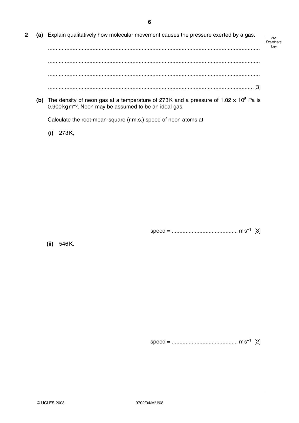
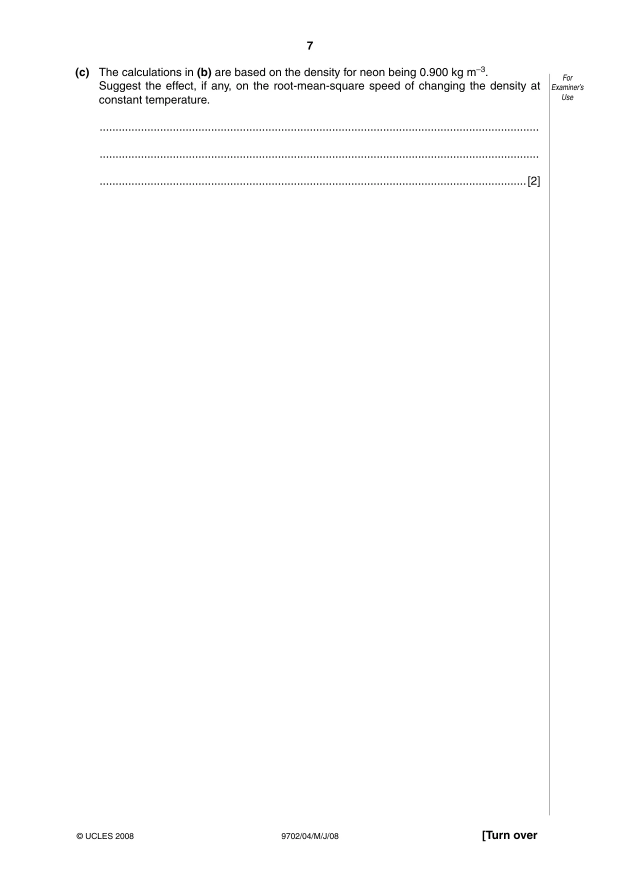
2 (a) Explain qualitatively how molecular movement causes the pressure exerted by a gas. For Examiner’s .......................................................................................................................................... Use .......................................................................................................................................... .......................................................................................................................................... ......................................................................................................................................[3] (b) The density of neon gas at a temperature of 273 K and a pressure of 1.02 × 10⁵ Pa is 0.900 kg m–3. Neon may be assumed to be an ideal gas. Calculate the root-mean-square (r.m.s.) speed of neon atoms at (i) 273 K, speed = ........................................... m s–1 [3] (ii) 546 K. speed = ........................................... m s–1 [2] (c) The calculations in (b) are based on the density for neon being 0.900 kg m–3. For Suggest the effect, if any, on the root-mean-square speed of changing the density at Examiner’s constant temperature. Use .......................................................................................................................................... .......................................................................................................................................... ......................................................................................................................................[2]
Mark scheme: 2 (a) molecule(s) rebound from wall of vessel / hits walls B1 change in momentum gives rise to impulse / force B1 either (many impulses) averaged to give constant force / pressure or the molecules are in random motion B1 [3] (b) (i) p = 1 ρ<c2> C1 3 1.02 × 105 = 1 × 0.900 × <c2> 3 <c2> = 3.4 × 10⁵ C1 cRMS = 580 m s–1 A1 [3] (ii) either <c2> ∝ T or <c2> = 2 × 3.4 ×105 C1 cRMS = 830 m s–1 (allow 820) A1 [2] (c) cRMS depends on temperature (alone) B1 so no effect B1 [2] GCE A/AS LEVEL – May/June 2008 9702 04
Q3 · A tube, closed at one end, has a uniform area of cross-section
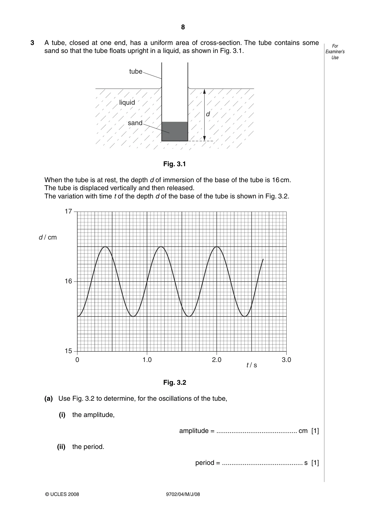
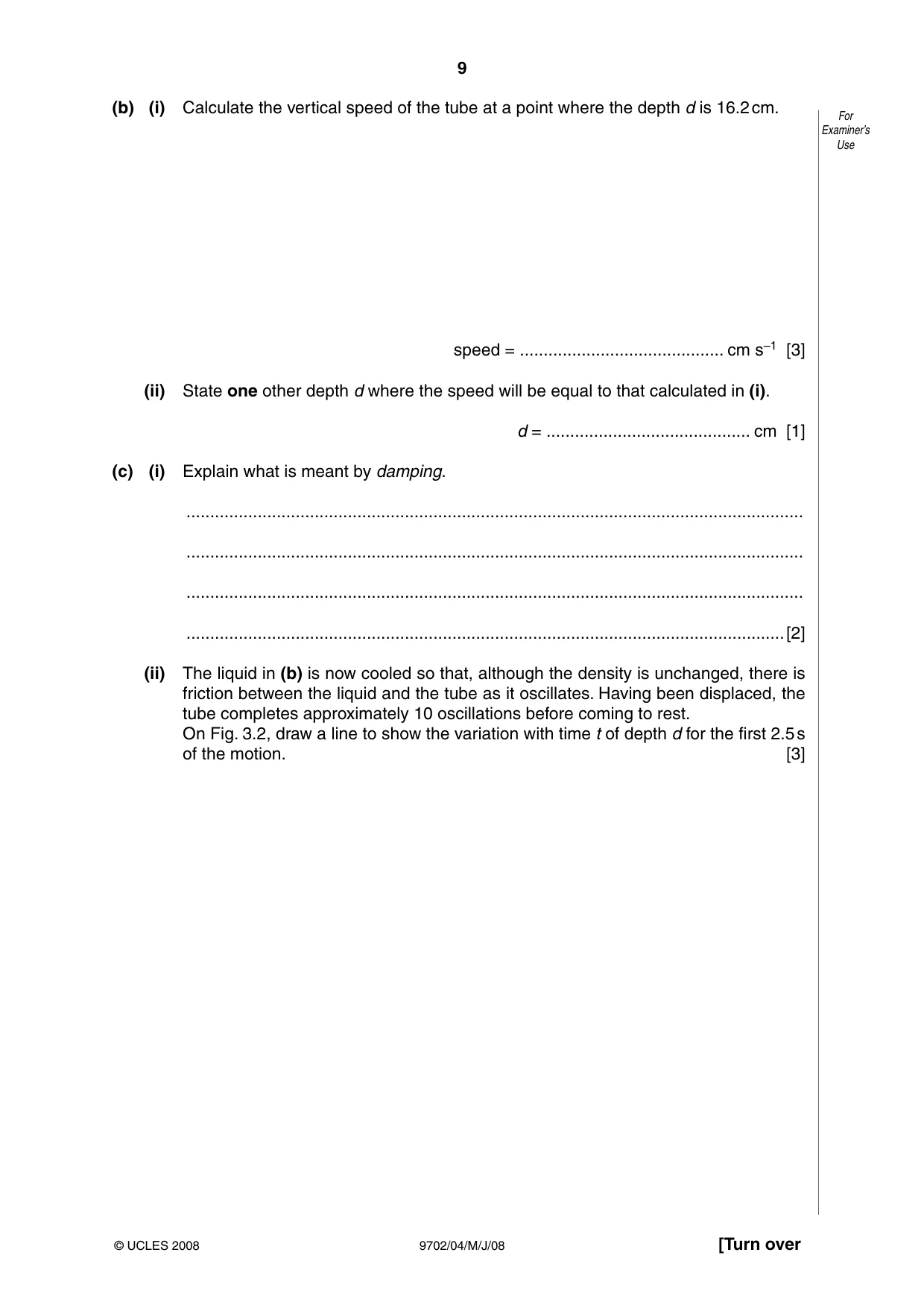
3 A tube, closed at one end, has a uniform area of cross-section. The tube contains some For sand so that the tube floats upright in a liquid, as shown in Fig. 3.1. Examiner’s Use tube liquid d sand Fig. 3.1 When the tube is at rest, the depth d of immersion of the base of the tube is 16 cm. The tube is displaced vertically and then released. The variation with time t of the depth d of the base of the tube is shown in Fig. 3.2. 17 d / cm 16 15 0 1.0 2.0 3.0 t / s Fig. 3.2 (a) Use Fig. 3.2 to determine, for the oscillations of the tube, (i) the amplitude, amplitude = ........................................... cm [1] (ii) the period. period = ........................................... s [1] (b) (i) Calculate the vertical speed of the tube at a point where the depth d is 16.2 cm. For Examiner’s Use speed = ........................................... cm s–1 [3] (ii) State one other depth d where the speed will be equal to that calculated in (i). d = ........................................... cm [1] (c) (i) Explain what is meant by damping. .................................................................................................................................. .................................................................................................................................. .................................................................................................................................. ..............................................................................................................................[2] (ii) The liquid in (b) is now cooled so that, although the density is unchanged, there is friction between the liquid and the tube as it oscillates. Having been displaced, the tube completes approximately 10 oscillations before coming to rest. On Fig. 3.2, draw a line to show the variation with time t of depth d for the first 2.5 s of the motion. [3]
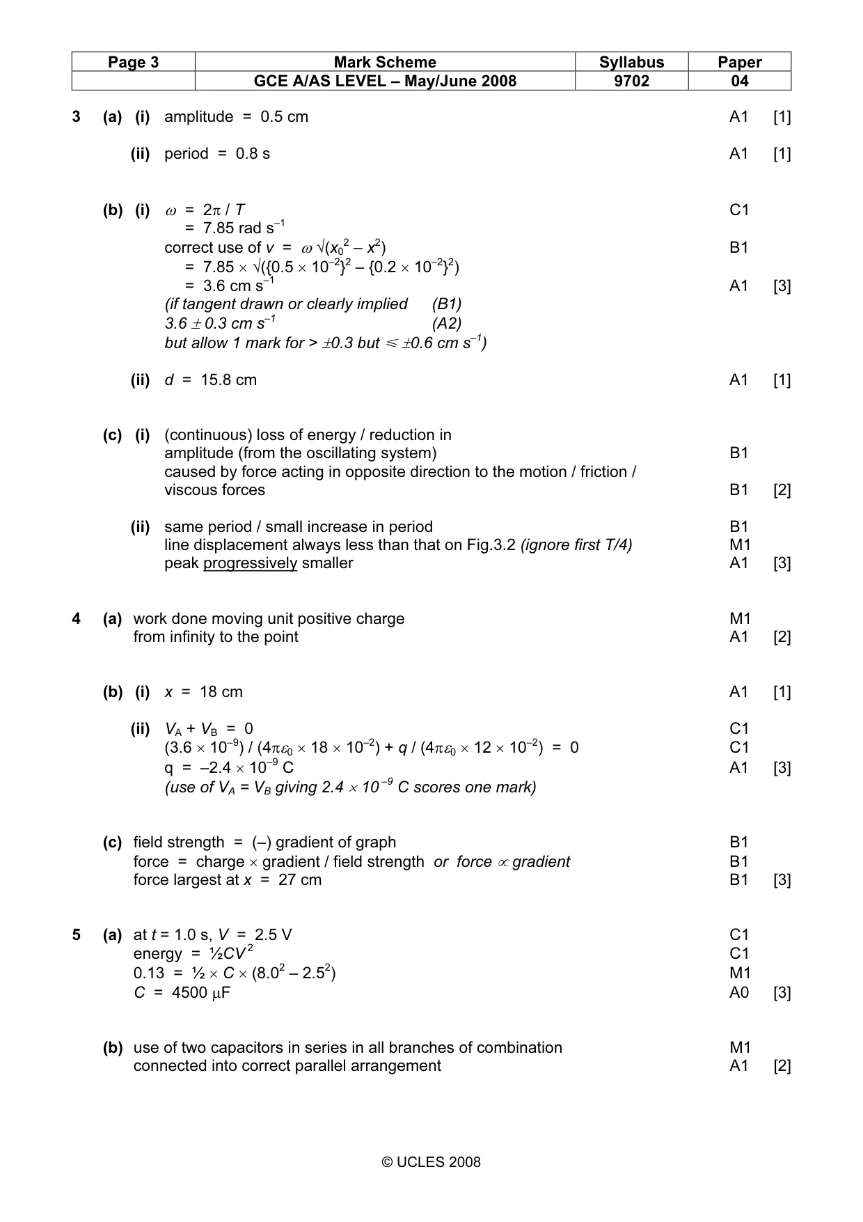
Mark scheme: 3 (a) (i) amplitude = 0.5 cm A1 [1] (ii) period = 0.8 s A1 [1] (b) (i) ω = 2π / T C1 = 7.85 rad s–1 correct use of v = ω √(x02 – x2) B1 = 7.85 × √({0.5 × 10⁻²}2 – {0.2 × 10⁻²}2) = 3.6 cm s–1 A1 [3] (if tangent drawn or clearly implied (B1) 3.6 ± 0.3 cm s–1 (A2) but allow 1 mark for > ±0.3 but Ğ ±0.6 cm s–1) (ii) d = 15.8 cm A1 [1] (c) (i) (continuous) loss of energy / reduction in amplitude (from the oscillating system) B1 caused by force acting in opposite direction to the motion / friction / viscous forces B1 [2] (ii) same period / small increase in period B1 line displacement always less than that on Fig.3.2 (ignore first T/4) M1 peak progressively smaller A1 [3]
Q4 · Define electric potential at a point
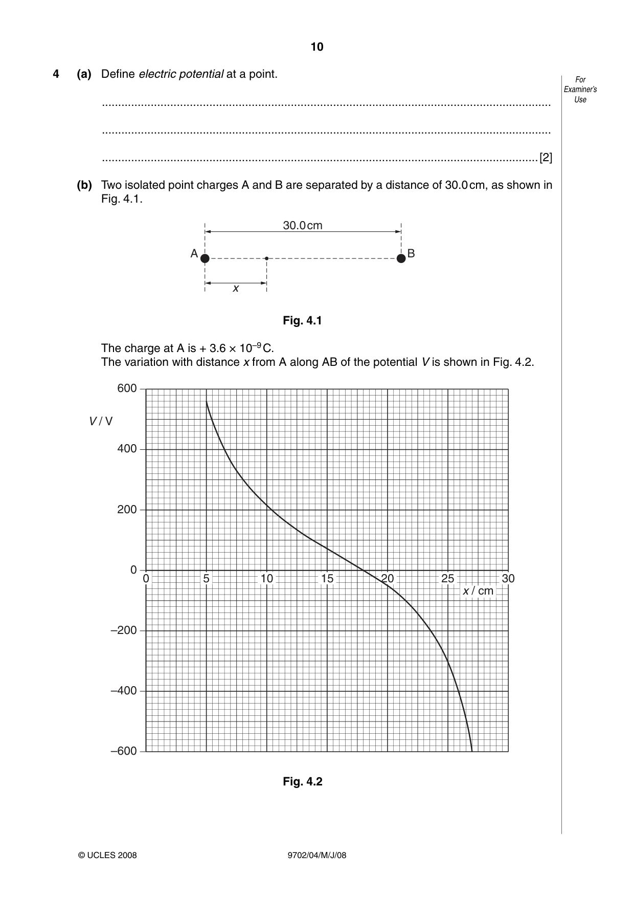
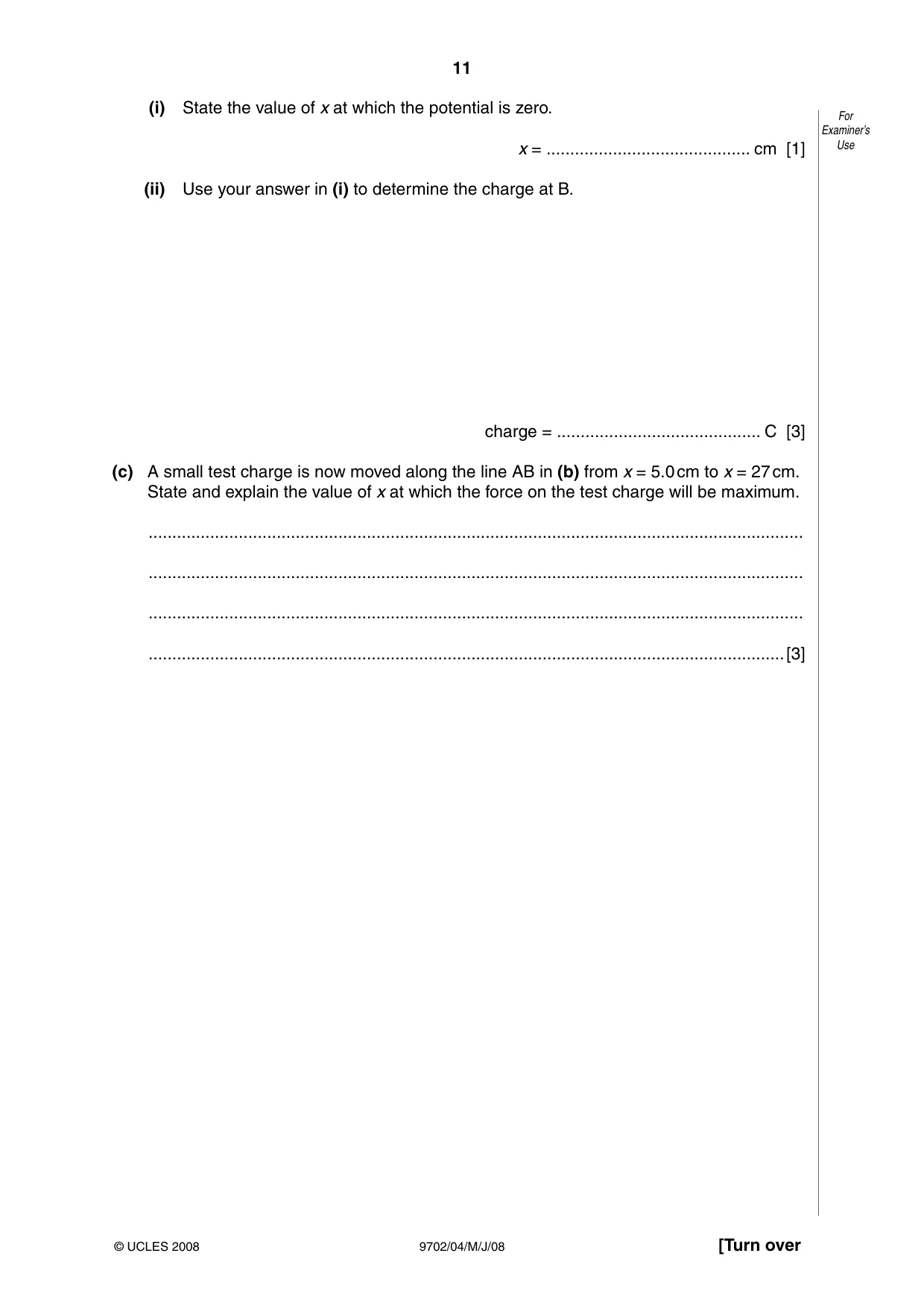
4 (a) Define electric potential at a point. For Examiner’s .......................................................................................................................................... Use .......................................................................................................................................... ......................................................................................................................................[2] (b) Two isolated point charges A and B are separated by a distance of 30.0 cm, as shown in Fig. 4.1. 30.0cm A B x Fig. 4.1 The charge at A is + 3.6 × 10⁻⁹ C. The variation with distance x from A along AB of the potential V is shown in Fig. 4.2. 600 V / V 400 200 0 0 5 10 15 20 25 30 x / cm –200 –400 –600 Fig. 4.2 (i) State the value of x at which the potential is zero. For Examiner’s x = ........................................... cm [1] Use (ii) Use your answer in (i) to determine the charge at B. charge = ........................................... C [3] (c) A small test charge is now moved along the line AB in (b) from x = 5.0 cm to x = 27 cm. State and explain the value of x at which the force on the test charge will be maximum. .......................................................................................................................................... .......................................................................................................................................... .......................................................................................................................................... ......................................................................................................................................[3]
Mark scheme: 4 (a) work done moving unit positive charge M1 from infinity to the point A1 [2] (b) (i) x = 18 cm A1 [1] (ii) VA + VB = 0 C1 (3.6 × 10⁻⁹) / (4πε0 × 18 × 10–2) + q / (4πε0 × 12 × 10–2) = 0 C1 q = –2.4 × 10⁻⁹ C A1 [3] (use of VA = VB giving 2.4 × 10 –9 C scores one mark) (c) field strength = (–) gradient of graph B1 force = charge × gradient / field strength or force ∝ gradient B1 force largest at x = 27 cm B1 [3]
Q5 · A capacitor C is charged using a supply of e.m.f
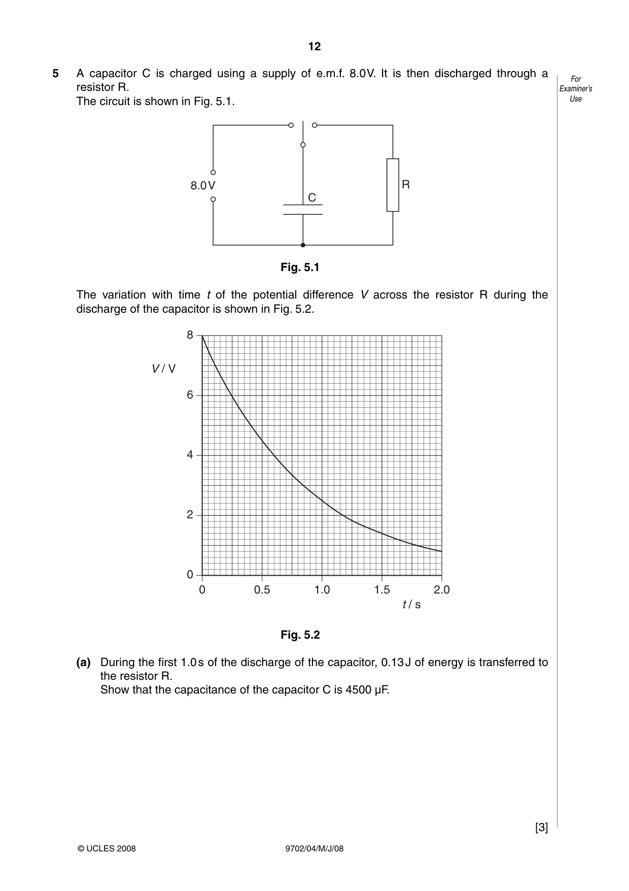
5 A capacitor C is charged using a supply of e.m.f. 8.0 V. It is then discharged through a For resistor R. Examiner’s The circuit is shown in Fig. 5.1. Use 8.0V R C Fig. 5.1 The variation with time t of the potential difference V across the resistor R during the discharge of the capacitor is shown in Fig. 5.2. 8 V / V 6 4 2 0 0 0.5 1.0 1.5 2.0 t / s Fig. 5.2 (a) During the first 1.0 s of the discharge of the capacitor, 0.13 J of energy is transferred to the resistor R. Show that the capacitance of the capacitor C is 4500 µF. [3] (b) Some capacitors, each of capacitance 4500 µF with a maximum working voltage of 6 V, For are available. Examiner’s Use Draw an arrangement of these capacitors that could provide a total capacitance of 4500 µF for use in the circuit of Fig. 5.1. [2]
Mark scheme: 5 (a) at t = 1.0 s, V = 2.5 V C1 energy = ½CV 2 C1 0.13 = ½ × C × (8.02 – 2.52) M1 C = 4500 µF A0 [3] (b) use of two capacitors in series in all branches of combination M1 connected into correct parallel arrangement A1 [2] GCE A/AS LEVEL – May/June 2008 9702 04
Q6 · A small rectangular coil ABCD contains 140 turns of wire
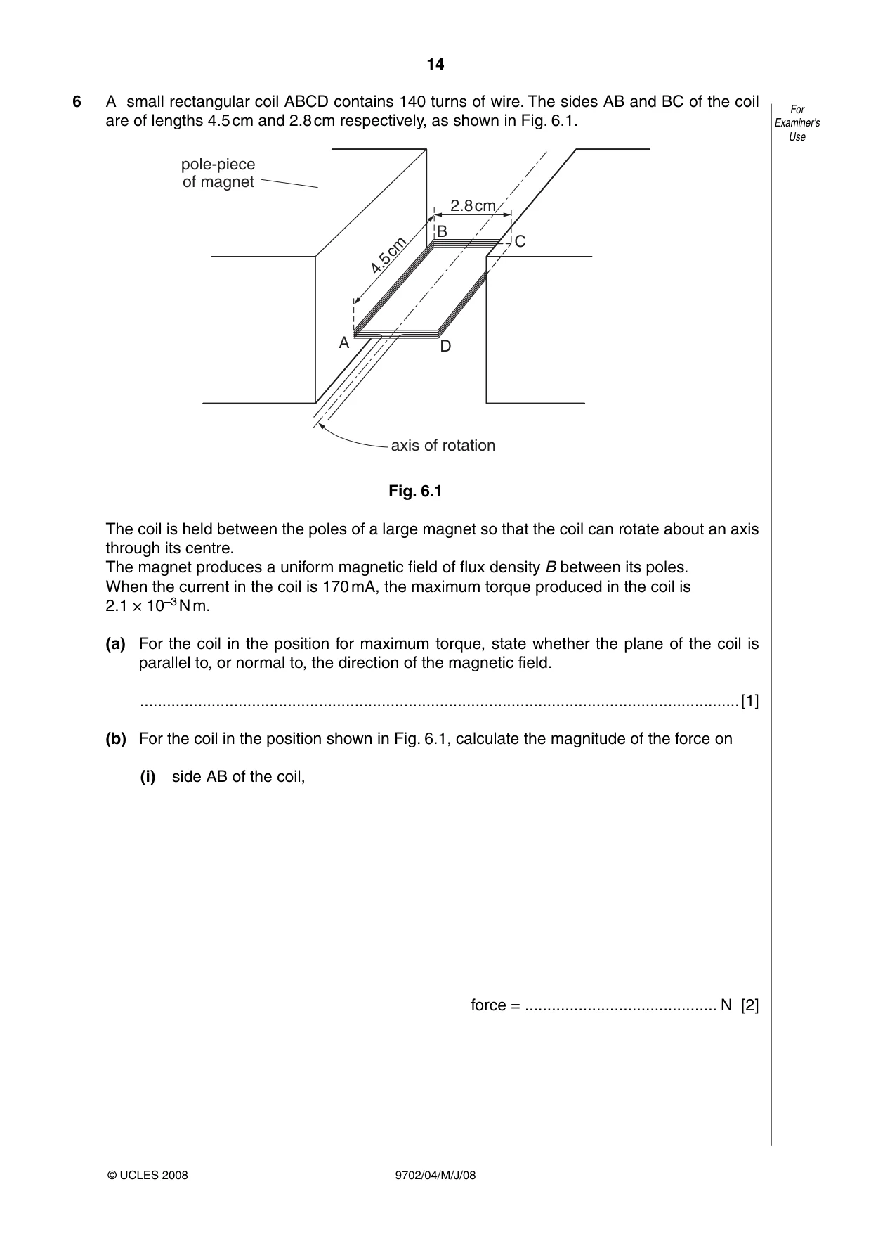
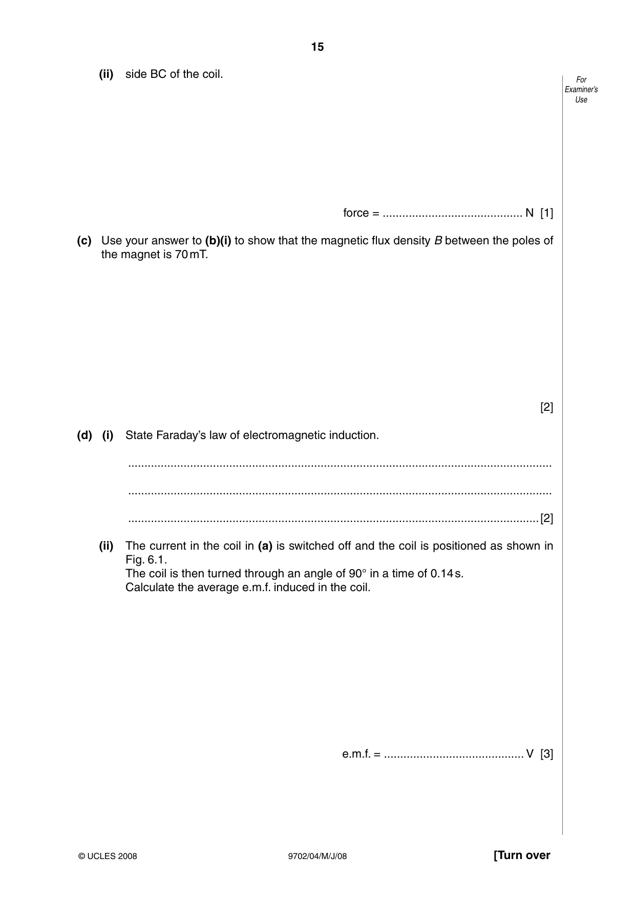
6 A small rectangular coil ABCD contains 140 turns of wire. The sides AB and BC of the coil For are of lengths 4.5 cm and 2.8 cm respectively, as shown in Fig. 6.1. Examiner’s Use pole-piece of magnet 2.8cm B 4.5cm C A D axis of rotation Fig. 6.1 The coil is held between the poles of a large magnet so that the coil can rotate about an axis through its centre. The magnet produces a uniform magnetic field of flux density B between its poles. When the current in the coil is 170 mA, the maximum torque produced in the coil is 2.1 × 10⁻³ N m. (a) For the coil in the position for maximum torque, state whether the plane of the coil is parallel to, or normal to, the direction of the magnetic field. ......................................................................................................................................[1] (b) For the coil in the position shown in Fig. 6.1, calculate the magnitude of the force on (i) side AB of the coil, force = ........................................... N [2] (ii) side BC of the coil. For Examiner’s Use force = ........................................... N [1] (c) Use your answer to (b)(i) to show that the magnetic flux density B between the poles of the magnet is 70 mT. [2] (d) (i) State Faraday’s law of electromagnetic induction. .................................................................................................................................. .................................................................................................................................. ..............................................................................................................................[2] (ii) The current in the coil in (a) is switched off and the coil is positioned as shown in Fig. 6.1. The coil is then turned through an angle of 90° in a time of 0.14 s. Calculate the average e.m.f. induced in the coil. e.m.f. = ........................................... V [3]
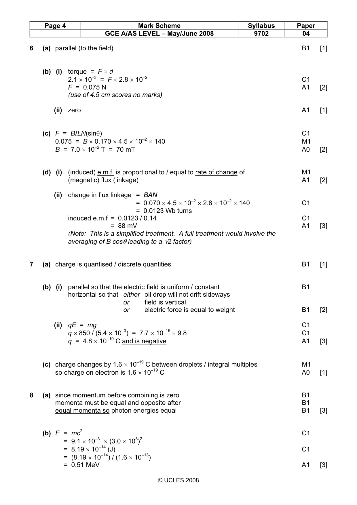
Mark scheme: 6 (a) parallel (to the field) B1 [1] (b) (i) torque = F × d 2.1 × 10–3 = F × 2.8 × 10⁻² C1 F = 0.075 N A1 [2] (use of 4.5 cm scores no marks) (ii) zero A1 [1] (c) F = BILN(sinθ) C1 0.075 = B × 0.170 × 4.5 × 10–2 × 140 M1 B = 7.0 × 10⁻² T = 70 mT A0 [2] (d) (i) (induced) e.m.f. is proportional to / equal to rate of change of M1 (magnetic) flux (linkage) A1 [2] (ii) change in flux linkage = BAN = 0.070 × 4.5 × 10–2 × 2.8 × 10–2 × 140 C1 = 0.0123 Wb turns induced e.m.f = 0.0123 / 0.14 C1 = 88 mV A1 [3] (Note: This is a simplified treatment. A full treatment would involve the averaging of B cosθ leading to a √2 factor)
Q7 · The Millikan oil-drop experiment enabled the charge on the electron to be determined
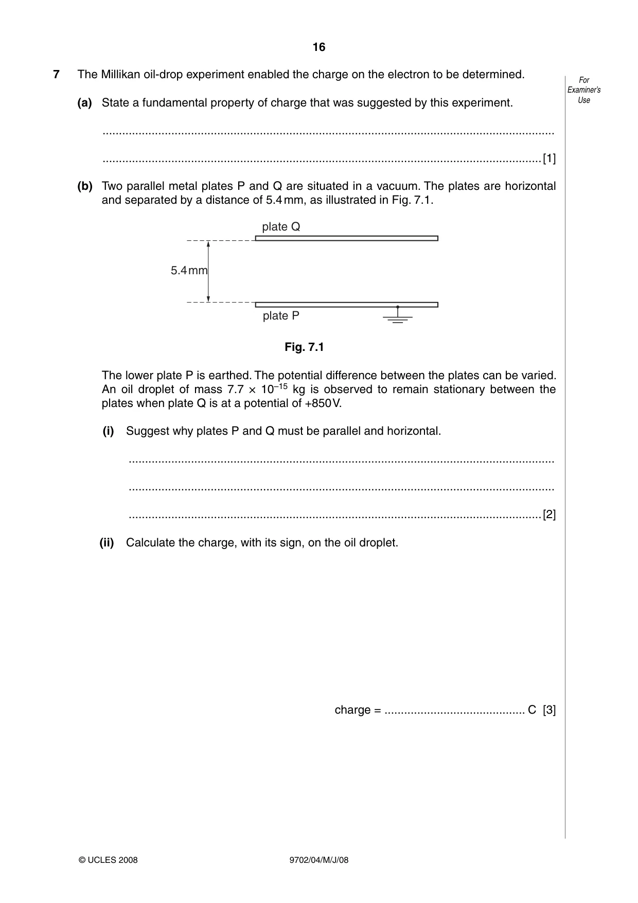
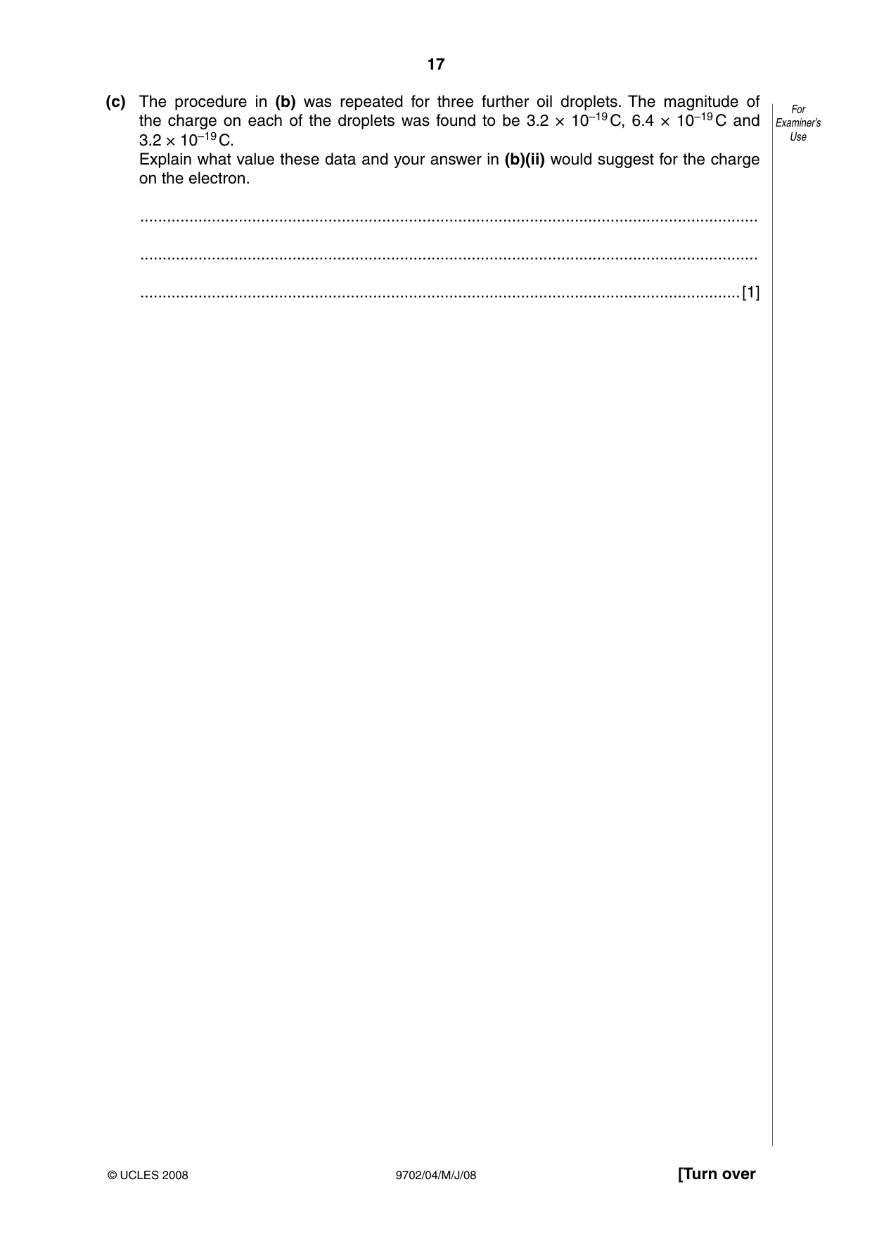
7 The Millikan oil-drop experiment enabled the charge on the electron to be determined. For Examiner’s (a) State a fundamental property of charge that was suggested by this experiment. Use .......................................................................................................................................... ......................................................................................................................................[1] (b) Two parallel metal plates P and Q are situated in a vacuum. The plates are horizontal and separated by a distance of 5.4 mm, as illustrated in Fig. 7.1. plate Q 5.4mm plate P Fig. 7.1 The lower plate P is earthed. The potential difference between the plates can be varied. An oil droplet of mass 7.7 × 10⁻¹⁵ kg is observed to remain stationary between the plates when plate Q is at a potential of +850 V. (i) Suggest why plates P and Q must be parallel and horizontal. .................................................................................................................................. .................................................................................................................................. ..............................................................................................................................[2] (ii) Calculate the charge, with its sign, on the oil droplet. charge = ........................................... C [3] (c) The procedure in (b) was repeated for three further oil droplets. The magnitude of For the charge on each of the droplets was found to be 3.2 × 10⁻¹⁹ C, 6.4 × 10⁻¹⁹ C and Examiner’s 3.2 × 10⁻¹⁹ C. Use Explain what value these data and your answer in (b)(ii) would suggest for the charge on the electron. .......................................................................................................................................... .......................................................................................................................................... ......................................................................................................................................[1]
Mark scheme: 7 (a) charge is quantised / discrete quantities B1 [1] (b) (i) parallel so that the electric field is uniform / constant B1 horizontal so that either oil drop will not drift sideways or field is vertical or electric force is equal to weight B1 [2] (ii) qE = mg C1 q × 850 / (5.4 × 10⁻³) = 7.7 × 10–15 × 9.8 C1 q = 4.8 × 10⁻¹⁹ C and is negative A1 [3] (c) charge changes by 1.6 × 10⁻¹⁹ C between droplets / integral multiples M1 so charge on electron is 1.6 × 10⁻¹⁹ C A0 [1]
Q8 · A positron ( +1e0 ) is a particle that has the same mass as an electron and has a charge…
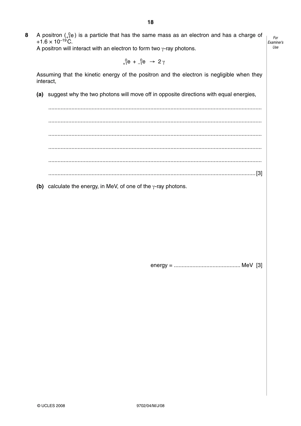
8 A positron ( +1e0 ) is a particle that has the same mass as an electron and has a charge of For +1.6 × 10⁻¹⁹ C. Examiner’s A positron will interact with an electron to form two γ-ray photons. Use +1e0 + –1e0 → 2 γ Assuming that the kinetic energy of the positron and the electron is negligible when they interact, (a) suggest why the two photons will move off in opposite directions with equal energies, .......................................................................................................................................... .......................................................................................................................................... .......................................................................................................................................... .......................................................................................................................................... .......................................................................................................................................... ......................................................................................................................................[3] (b) calculate the energy, in MeV, of one of the γ-ray photons. energy = ........................................... MeV [3]
Mark scheme: 8 (a) since momentum before combining is zero B1 momenta must be equal and opposite after B1 equal momenta so photon energies equal B1 [3] (b) E = mc2 C1 = 9.1 × 10–31 × (3.0 × 108)2 = 8.19 × 10⁻¹⁴ (J) C1 = (8.19 × 10⁻¹⁴) / (1.6 × 10⁻¹³) = 0.51 MeV A1 [3] GCE A/AS LEVEL – May/June 2008 9702 04 Section B
Q9 · A block diagram for an electronic sensor is shown in Fig
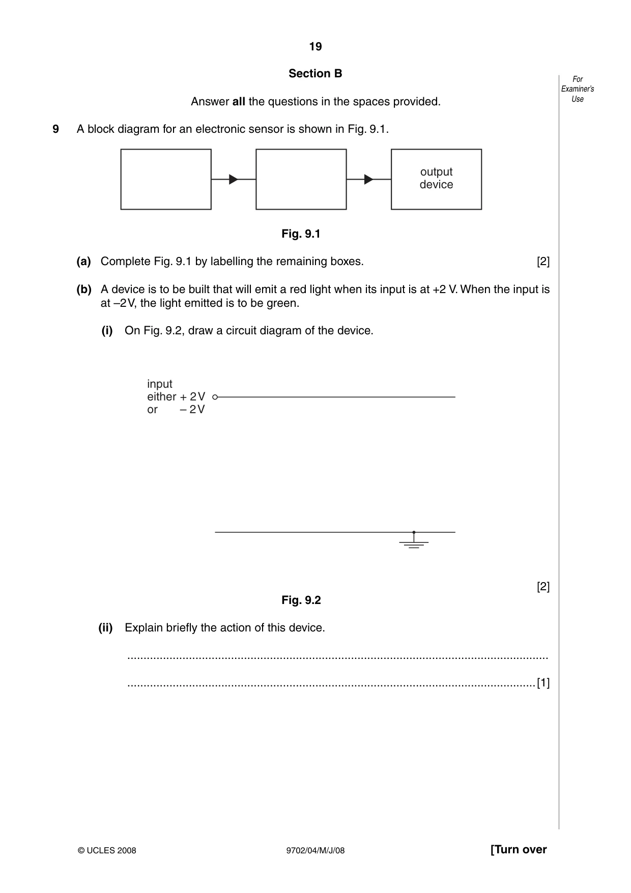
9 A block diagram for an electronic sensor is shown in Fig. 9.1. output device Fig. 9.1 (a) Complete Fig. 9.1 by labelling the remaining boxes. [2] (b) A device is to be built that will emit a red light when its input is at +2 V. When the input is at –2 V, the light emitted is to be green. (i) On Fig. 9.2, draw a circuit diagram of the device. input either + 2V or – 2V [2] Fig. 9.2 (ii) Explain briefly the action of this device. .................................................................................................................................. ..............................................................................................................................[1]
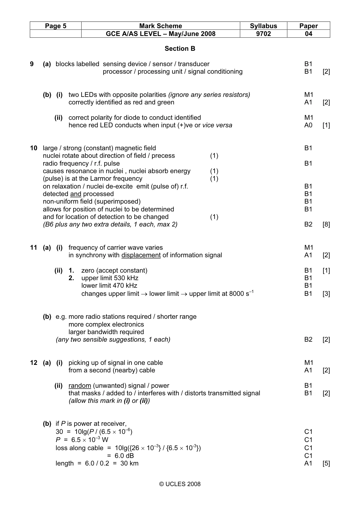
Mark scheme: 9 (a) blocks labelled sensing device / sensor / transducer B1 processor / processing unit / signal conditioning B1 [2] (b) (i) two LEDs with opposite polarities (ignore any series resistors) M1 correctly identified as red and green A1 [2] (ii) correct polarity for diode to conduct identified M1 hence red LED conducts when input (+)ve or vice versa A0 [1]
Q10 · Outline briefly the main principles of the use of magnetic resonance to obtain…
10 Outline briefly the main principles of the use of magnetic resonance to obtain information For about internal body structures. Examiner’s Use ................................................................................................................................................. ................................................................................................................................................. ................................................................................................................................................. ................................................................................................................................................. ................................................................................................................................................. ................................................................................................................................................. ................................................................................................................................................. ................................................................................................................................................. ................................................................................................................................................. ................................................................................................................................................. ................................................................................................................................................. .............................................................................................................................................[8]
Mark scheme: 10 large / strong (constant) magnetic field B1 nuclei rotate about direction of field / precess (1) radio frequency / r.f. pulse B1 causes resonance in nuclei , nuclei absorb energy (1) (pulse) is at the Larmor frequency (1) on relaxation / nuclei de-excite emit (pulse of) r.f. B1 detected and processed B1 non-uniform field (superimposed) B1 allows for position of nuclei to be determined B1 and for location of detection to be changed (1) (B6 plus any two extra details, 1 each, max 2) B2 [8]
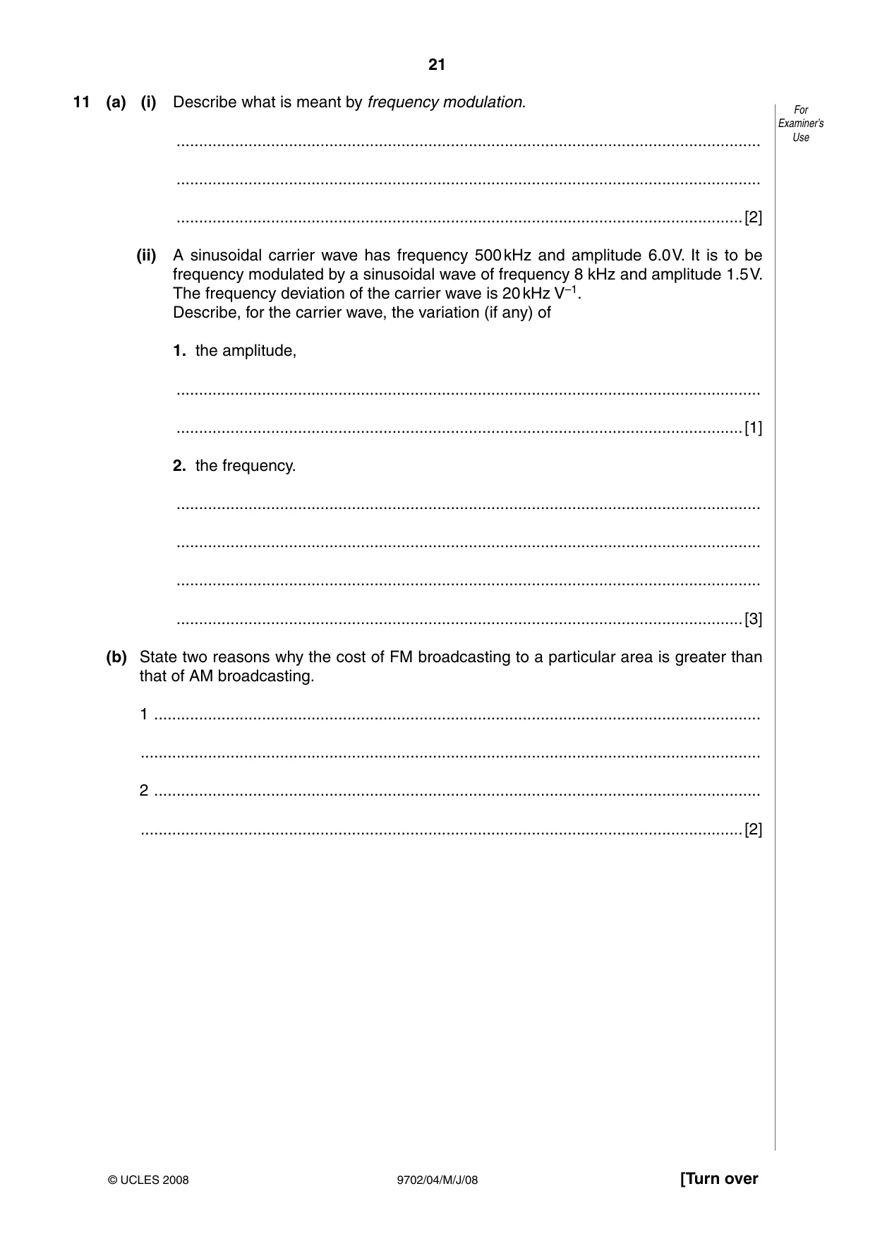
Q11 · Describe what is meant by frequency modulation
11 (a) (i) Describe what is meant by frequency modulation. For Examiner’s .................................................................................................................................. Use .................................................................................................................................. ..............................................................................................................................[2] (ii) A sinusoidal carrier wave has frequency 500 kHz and amplitude 6.0 V. It is to be frequency modulated by a sinusoidal wave of frequency 8 kHz and amplitude 1.5 V. The frequency deviation of the carrier wave is 20 kHz V–1. Describe, for the carrier wave, the variation (if any) of 1. the amplitude, .................................................................................................................................. ..............................................................................................................................[1] 2. the frequency. .................................................................................................................................. .................................................................................................................................. .................................................................................................................................. ..............................................................................................................................[3] (b) State two reasons why the cost of FM broadcasting to a particular area is greater than that of AM broadcasting. 1 ....................................................................................................................................... .......................................................................................................................................... 2 ....................................................................................................................................... ......................................................................................................................................[2]
Mark scheme: 11 (a) (i) frequency of carrier wave varies M1 in synchrony with displacement of information signal A1 [2] (ii) 1. zero (accept constant) B1 [1] 2. upper limit 530 kHz B1 lower limit 470 kHz B1 changes upper limit → lower limit → upper limit at 8000 s–1 B1 [3] (b) e.g. more radio stations required / shorter range more complex electronics larger bandwidth required (any two sensible suggestions, 1 each) B2 [2]
Q12 · Optic fibre transmission has, in some instances, replaced transmission using co-axial For…
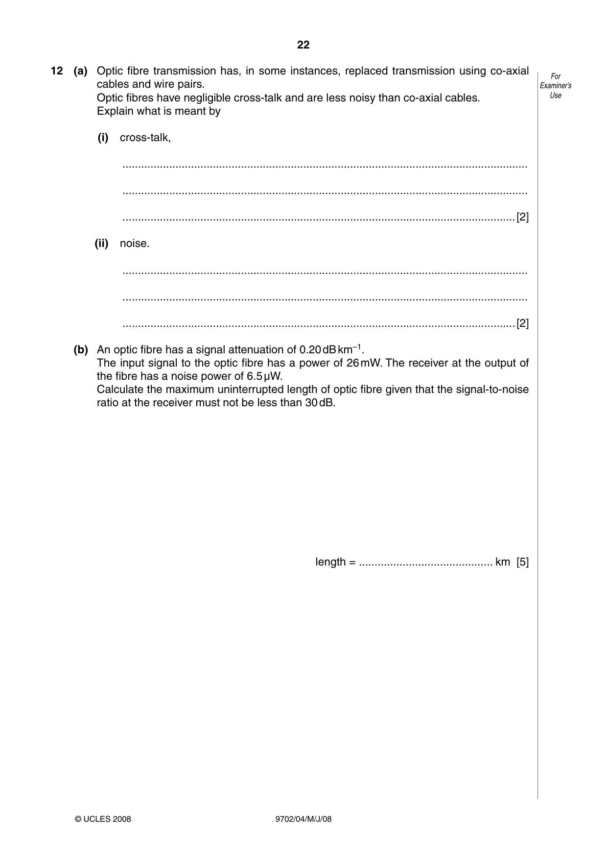
12 (a) Optic fibre transmission has, in some instances, replaced transmission using co-axial For cables and wire pairs. Examiner’s Optic fibres have negligible cross-talk and are less noisy than co-axial cables. Use Explain what is meant by (i) cross-talk, .................................................................................................................................. .................................................................................................................................. ..............................................................................................................................[2] (ii) noise. .................................................................................................................................. .................................................................................................................................. ..............................................................................................................................[2] (b) An optic fibre has a signal attenuation of 0.20 dB km–1. The input signal to the optic fibre has a power of 26 mW. The receiver at the output of the fibre has a noise power of 6.5 µW. Calculate the maximum uninterrupted length of optic fibre given that the signal-to-noise ratio at the receiver must not be less than 30 dB. length = ........................................... km [5]
Mark scheme: 12 (a) (i) picking up of signal in one cable M1 from a second (nearby) cable A1 [2] (ii) random (unwanted) signal / power B1 that masks / added to / interferes with / distorts transmitted signal B1 [2] (allow this mark in (i) or (ii)) (b) if P is power at receiver, 30 = 10lg(P / (6.5 × 10⁻⁶) C1 P = 6.5 × 10⁻³ W C1 loss along cable = 10lg({26 × 10–3} / {6.5 × 10⁻³}) C1 = 6.0 dB C1 length = 6.0 / 0.2 = 30 km A1 [5]
What was in this paper
The subtopics covered by these 12 questions, and how many questions each got. Open one in a new tab to see every Cambridge question on it.
2Electric fields and field lines1Electric potential1Electromagnetic induction1Energy stored in a capacitor1Kinematics of uniform circular motion1Kinetic theory of gases1Linear momentum and its conservation1Practical circuits1Production and use of ultrasound1Simple harmonic oscillations1What you needed in this session
Cambridge’s own grade thresholds for 2008 May/June, Paper 4 · Variant 1. A higher threshold means an easier paper — the bar moves with how the cohort did.