Cambridge A Level Physics 9702 — 2007 Oct/Nov Paper 4 · Variant 1
9702/41/O/N/07 · 11 questions · 100 marks · ≈113 min
The question paper and its mark scheme, free to read here and free to download. This is Cambridge’s own paper, exactly as it was sat.
Question paper24 pages

Mark scheme7 pages
Answers below. Sit the paper first if you are practising.
Questions as text
Q1 · Explain (i) what is meant by a radian…
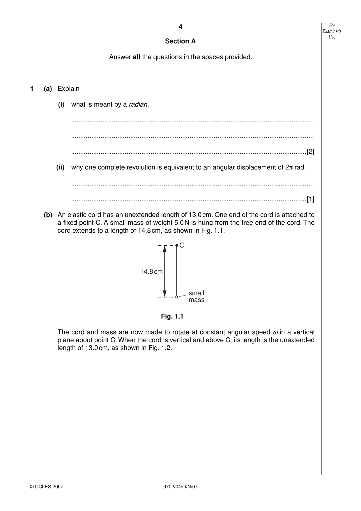
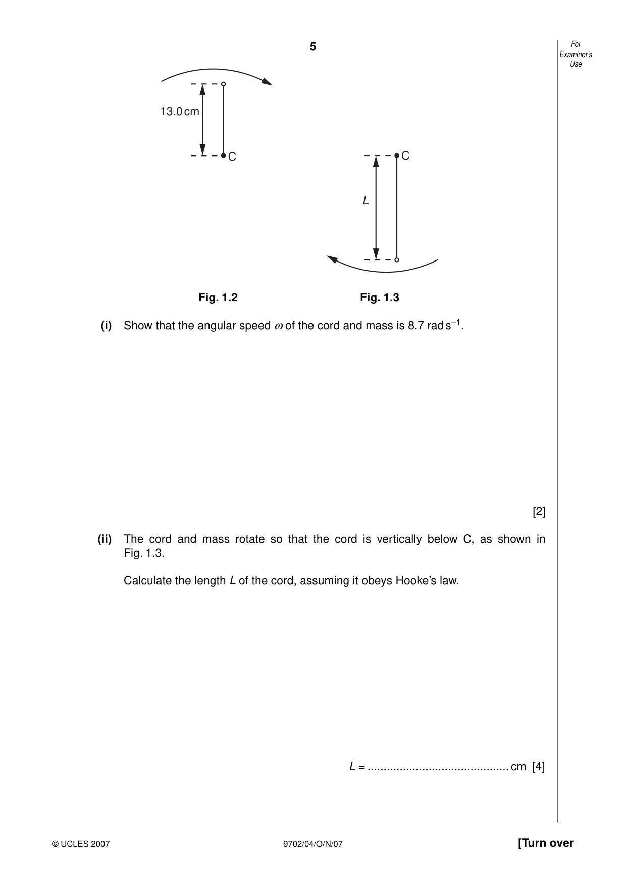
1 (a) Explain (i) what is meant by a radian, .................................................................................................................................. .................................................................................................................................. ..............................................................................................................................[2] (ii) why one complete revolution is equivalent to an angular displacement of 2π rad. .................................................................................................................................. ..............................................................................................................................[1] (b) An elastic cord has an unextended length of 13.0 cm. One end of the cord is attached to a fixed point C. A small mass of weight 5.0 N is hung from the free end of the cord. The cord extends to a length of 14.8 cm, as shown in Fig. 1.1. C 14.8 cm small mass Fig. 1.1 The cord and mass are now made to rotate at constant angular speed ω in a vertical plane about point C. When the cord is vertical and above C, its length is the unextended length of 13.0 cm, as shown in Fig. 1.2. Examiner’s Use 13.0 cm C C L Fig. 1.2 Fig. 1.3 (i) Show that the angular speed ω of the cord and mass is 8.7 rad s–1. [2] (ii) The cord and mass rotate so that the cord is vertically below C, as shown in Fig. 1.3. Calculate the length L of the cord, assuming it obeys Hooke’s law. L = ............................................ cm [4]
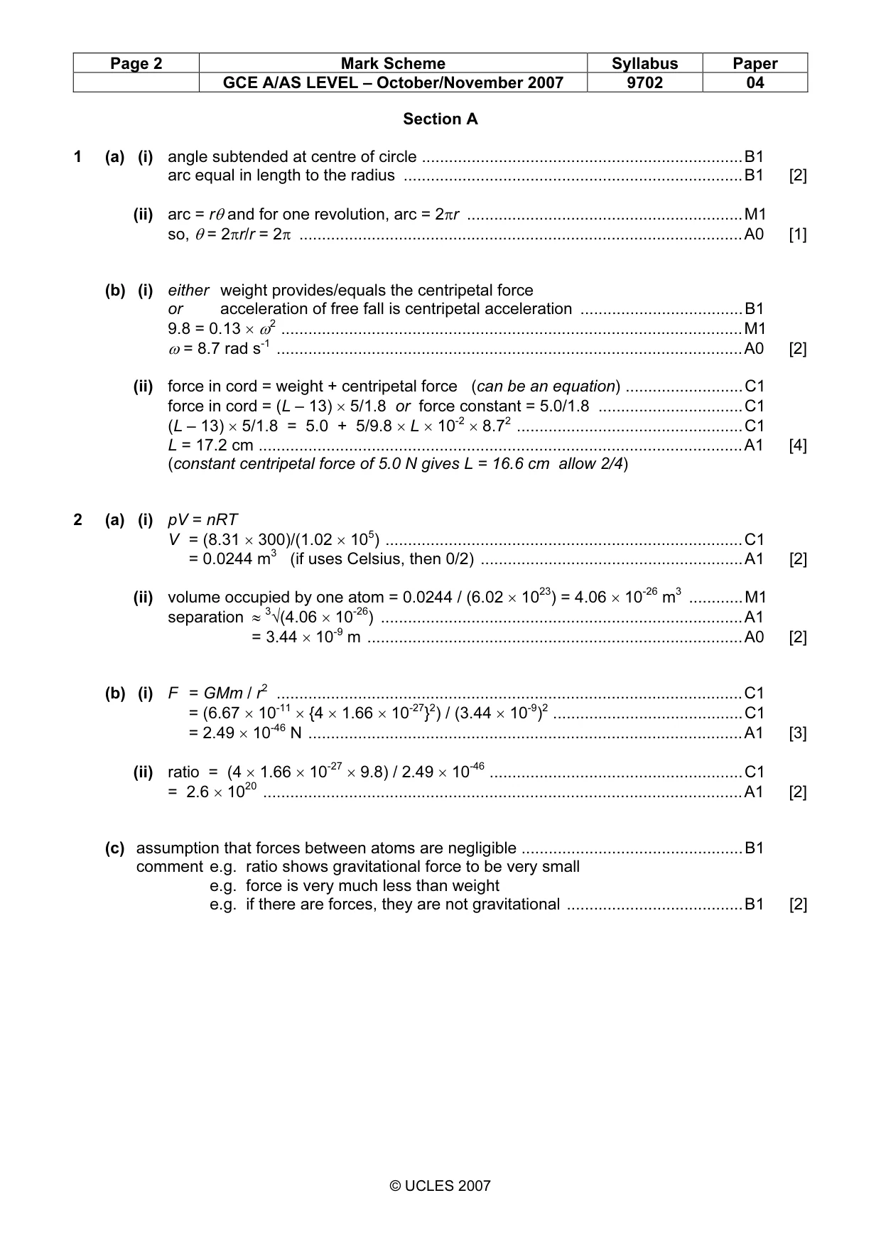
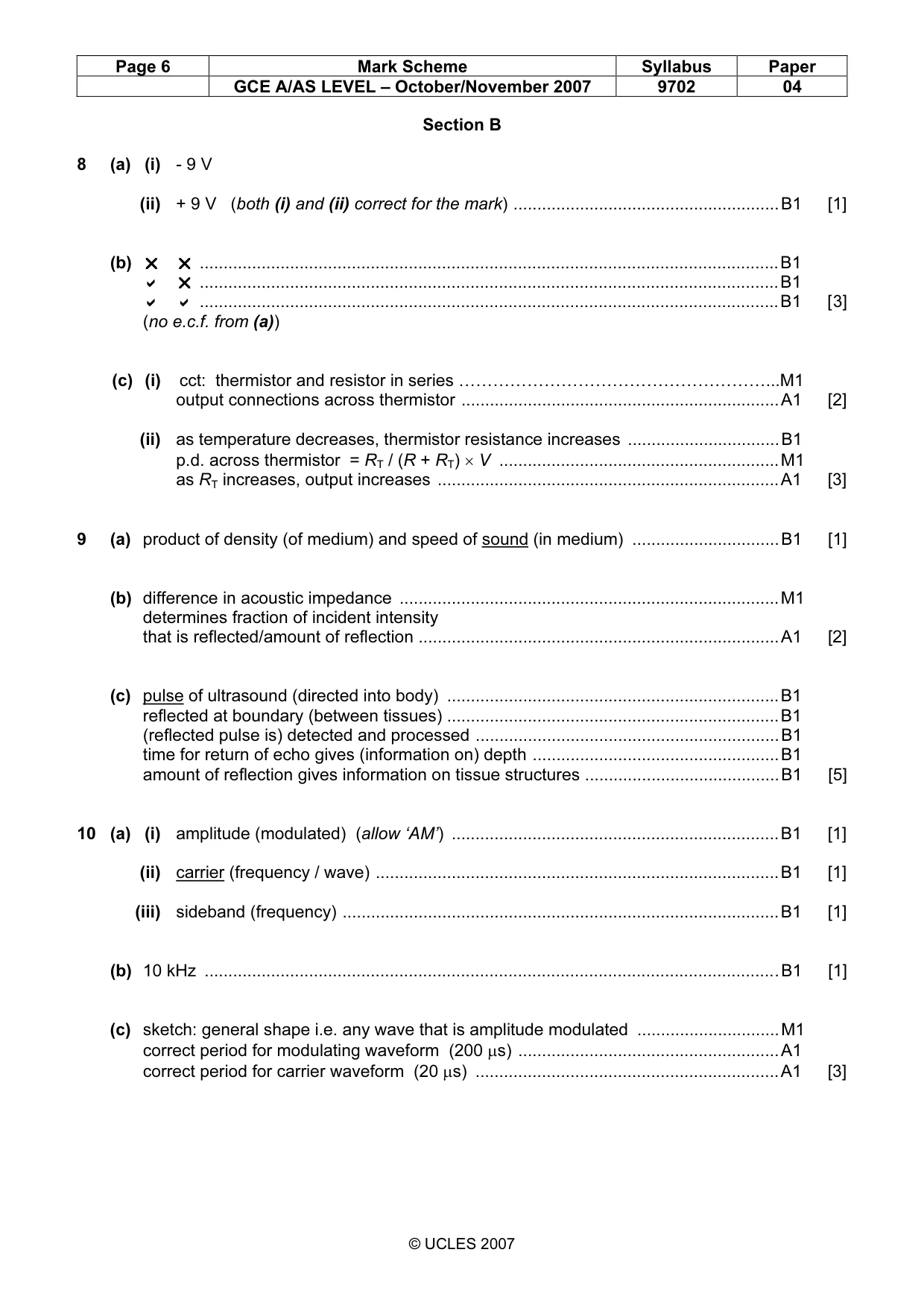
Mark scheme: 1 (a) (i) angle subtended at centre of circle .......................................................................B1 arc equal in length to the radius ...........................................................................B1 [2] (ii) arc = rθ and for one revolution, arc = 2πr .............................................................M1 so, θ = 2πr/r = 2π ..................................................................................................A0 [1] (b) (i) either weight provides/equals the centripetal force or acceleration of free fall is centripetal acceleration ....................................B1 9.8 = 0.13 × ω2 ......................................................................................................M1 ω = 8.7 rad s-1 .......................................................................................................A0 [2] (ii) force in cord = weight + centripetal force (can be an equation) ..........................C1 force in cord = (L – 13) × 5/1.8 or force constant = 5.0/1.8 ................................C1 (L – 13) × 5/1.8 = 5.0 + 5/9.8 × L × 10-2 × 8.72 ..................................................C1 L = 17.2 cm ...........................................................................................................A1 [4] (constant centripetal force of 5.0 N gives L = 16.6 cm allow 2/4)
Q2 · An amount of 1.00 mol of Helium-4 gas is contained in a cylinder at a pressure of 1.02 ×…
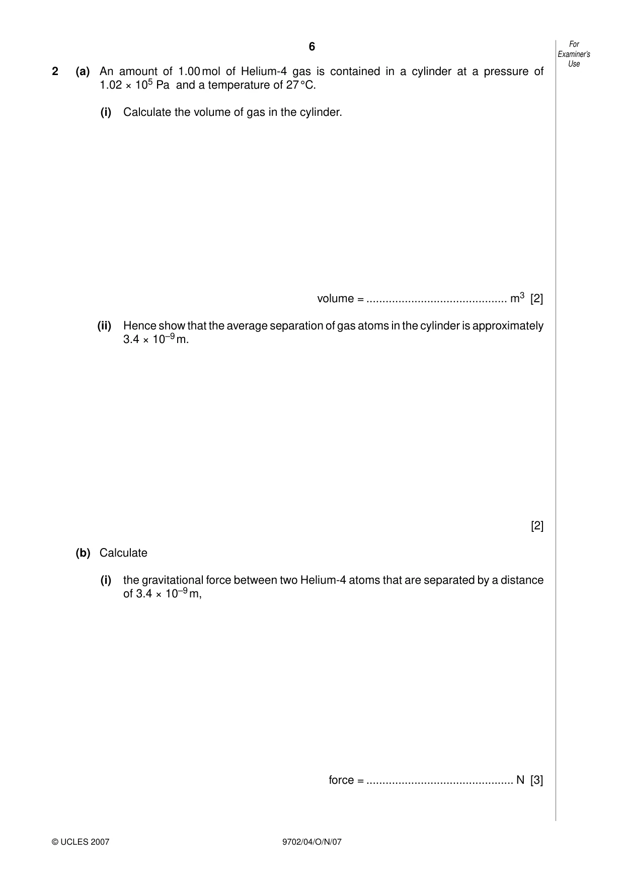
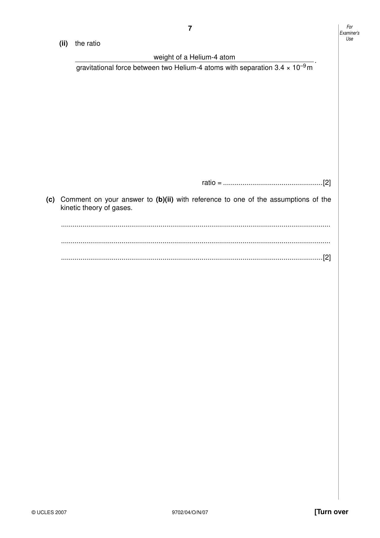
2 (a) An amount of 1.00 mol of Helium-4 gas is contained in a cylinder at a pressure of 1.02 × 10⁵ Pa and a temperature of 27 °C. (i) Calculate the volume of gas in the cylinder. volume = ............................................ m3 [2] (ii) Hence show that the average separation of gas atoms in the cylinder is approximately 3.4 × 10⁻⁹ m. [2] (b) Calculate (i) the gravitational force between two Helium-4 atoms that are separated by a distance of 3.4 × 10⁻⁹ m, force = .............................................. N [3] Examiner’s Use (ii) the ratio weight of a Helium-4 atom . gravitational force between two Helium-4 atoms with separation 3.4 × 10⁻⁹ m ratio = ...................................................[2] (c) Comment on your answer to (b)(ii) with reference to one of the assumptions of the kinetic theory of gases. .......................................................................................................................................... .......................................................................................................................................... ......................................................................................................................................[2]
Mark scheme: 2 (a) (i) pV = nRT V = (8.31 × 300)/(1.02 × 105) ...............................................................................C1 = 0.0244 m3 (if uses Celsius, then 0/2) ..........................................................A1 [2] (ii) volume occupied by one atom = 0.0244 / (6.02 × 10²³) = 4.06 × 10⁻²⁶ m3 ............M1 separation ≈ 3√(4.06 × 10⁻²⁶) ................................................................................A1 = 3.44 × 10⁻⁹ m ...................................................................................A0 [2] (b) (i) F = GMm / r2 .......................................................................................................C1 = (6.67 × 10⁻¹¹ × {4 × 1.66 × 10-27}2) / (3.44 × 10⁻⁹)2 ..........................................C1 = 2.49 × 10-46 N ................................................................................................A1 [3] (ii) ratio = (4 × 1.66 × 10-27 × 9.8) / 2.49 × 10-46 ........................................................C1 = 2.6 × 10²⁰ ..........................................................................................................A1 [2] (c) assumption that forces between atoms are negligible .................................................B1 comment e.g. ratio shows gravitational force to be very small e.g. force is very much less than weight e.g. if there are forces, they are not gravitational .......................................B1 [2] GCE A/AS LEVEL – October/November 2007 9702 04
Q3 · A spring is hung from a fixed point
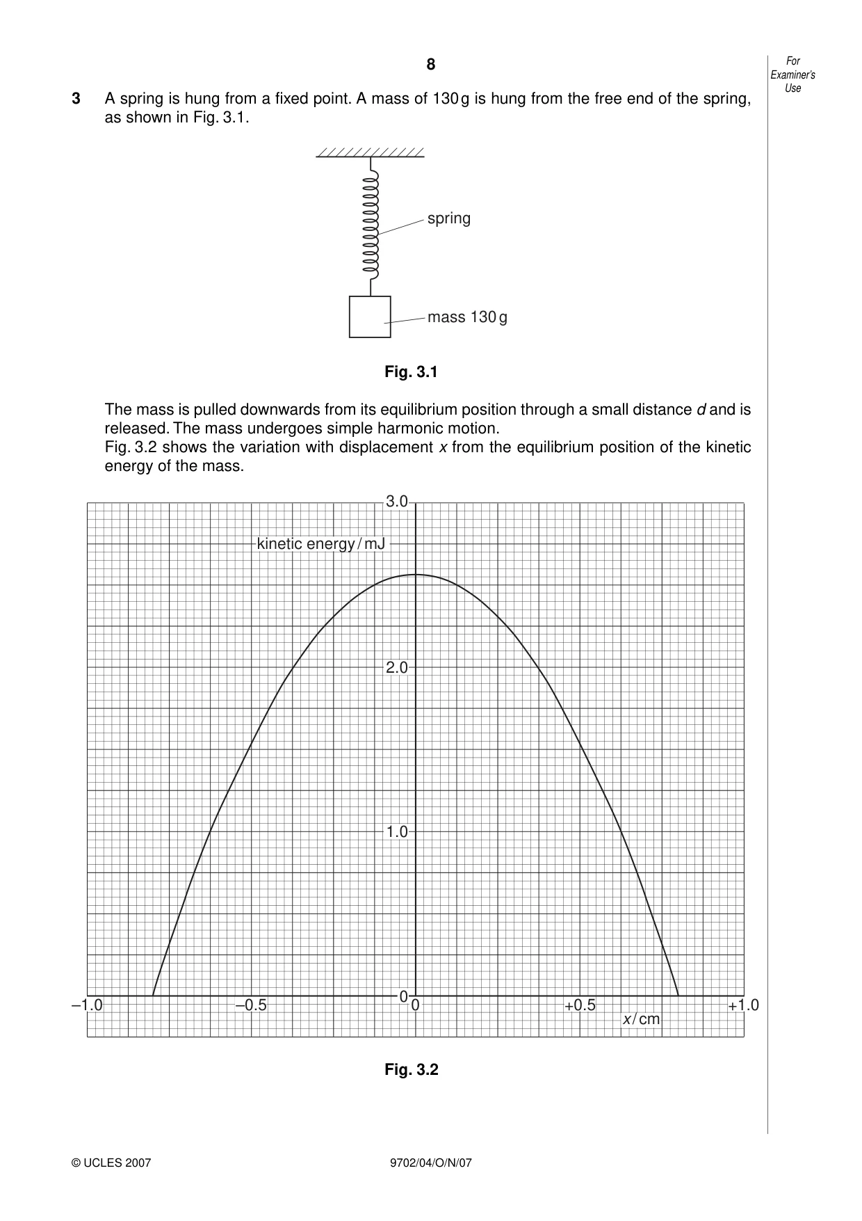
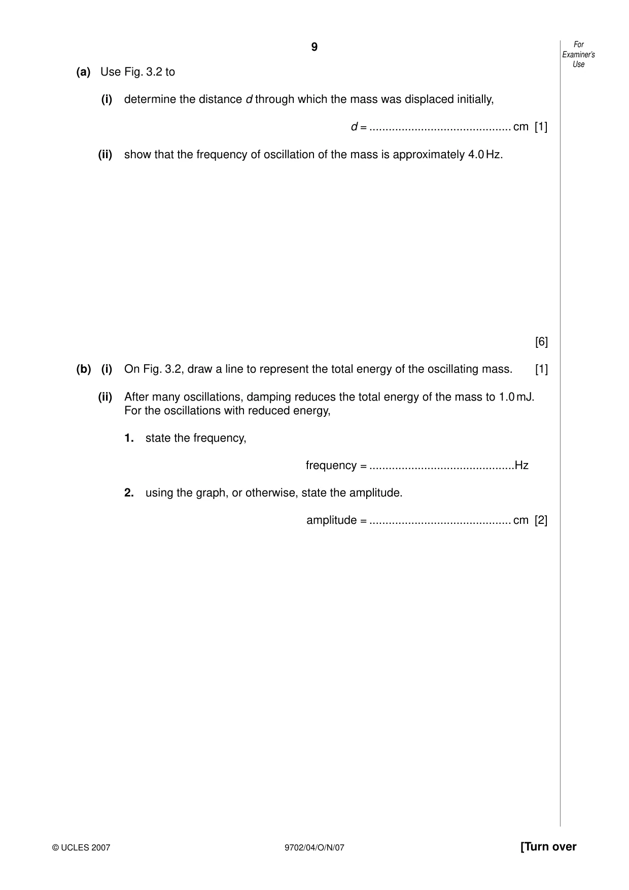
3 A spring is hung from a fixed point. A mass of 130 g is hung from the free end of the spring, as shown in Fig. 3.1. spring mass 130 g Fig. 3.1 The mass is pulled downwards from its equilibrium position through a small distance d and is released. The mass undergoes simple harmonic motion. Fig. 3.2 shows the variation with displacement x from the equilibrium position of the kinetic energy of the mass. 3.0 kinetic energy / mJ 2.0 1.0 0 –1.0 –0.5 0 +0.5 +1.0 x / cm Fig. 3.2 Examiner’s Use (a) Use Fig. 3.2 to (i) determine the distance d through which the mass was displaced initially, d = ............................................ cm [1] (ii) show that the frequency of oscillation of the mass is approximately 4.0 Hz. [6] (b) (i) On Fig. 3.2, draw a line to represent the total energy of the oscillating mass. [1] (ii) After many oscillations, damping reduces the total energy of the mass to 1.0 mJ. For the oscillations with reduced energy, 1. state the frequency, frequency = .............................................Hz 2. using the graph, or otherwise, state the amplitude. amplitude = ............................................ cm [2]
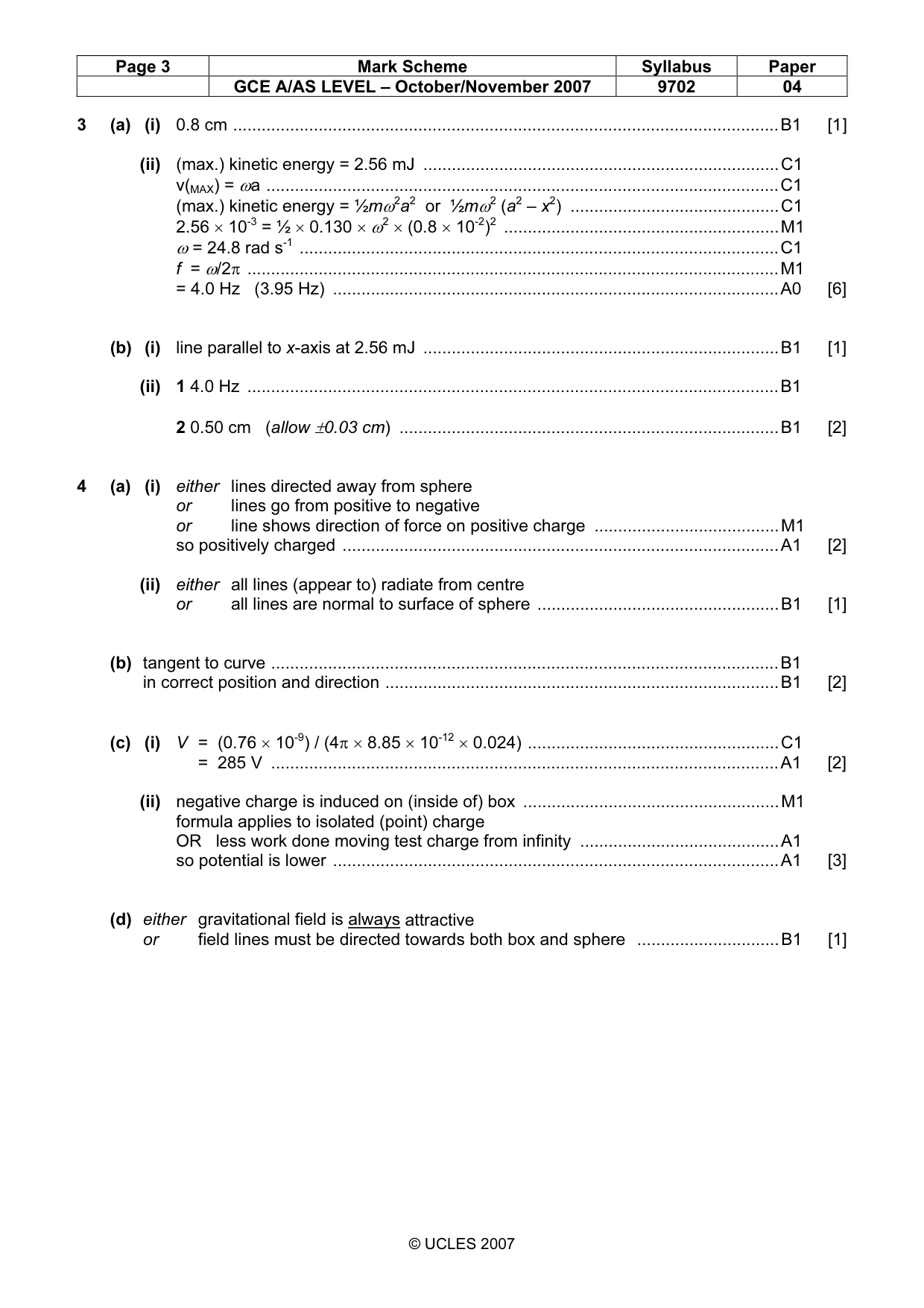
Mark scheme: 3 (a) (i) 0.8 cm ...................................................................................................................B1 [1] (ii) (max.) kinetic energy = 2.56 mJ ...........................................................................C1 v(MAX) = ωa ............................................................................................................C1 (max.) kinetic energy = ½mω2a2 or ½mω2 (a2 – x2) ............................................C1 2.56 × 10-3 = ½ × 0.130 × ω2 × (0.8 × 10-2)2 ..........................................................M1 ω = 24.8 rad s-1 .....................................................................................................C1 f = ω/2π ................................................................................................................M1 = 4.0 Hz (3.95 Hz) ..............................................................................................A0 [6] (b) (i) line parallel to x-axis at 2.56 mJ ...........................................................................B1 [1] (ii) 1 4.0 Hz ................................................................................................................B1 2 0.50 cm (allow ±0.03 cm) ................................................................................B1 [2]
Q4 · A small charged metal sphere is situated in an earthed metal box
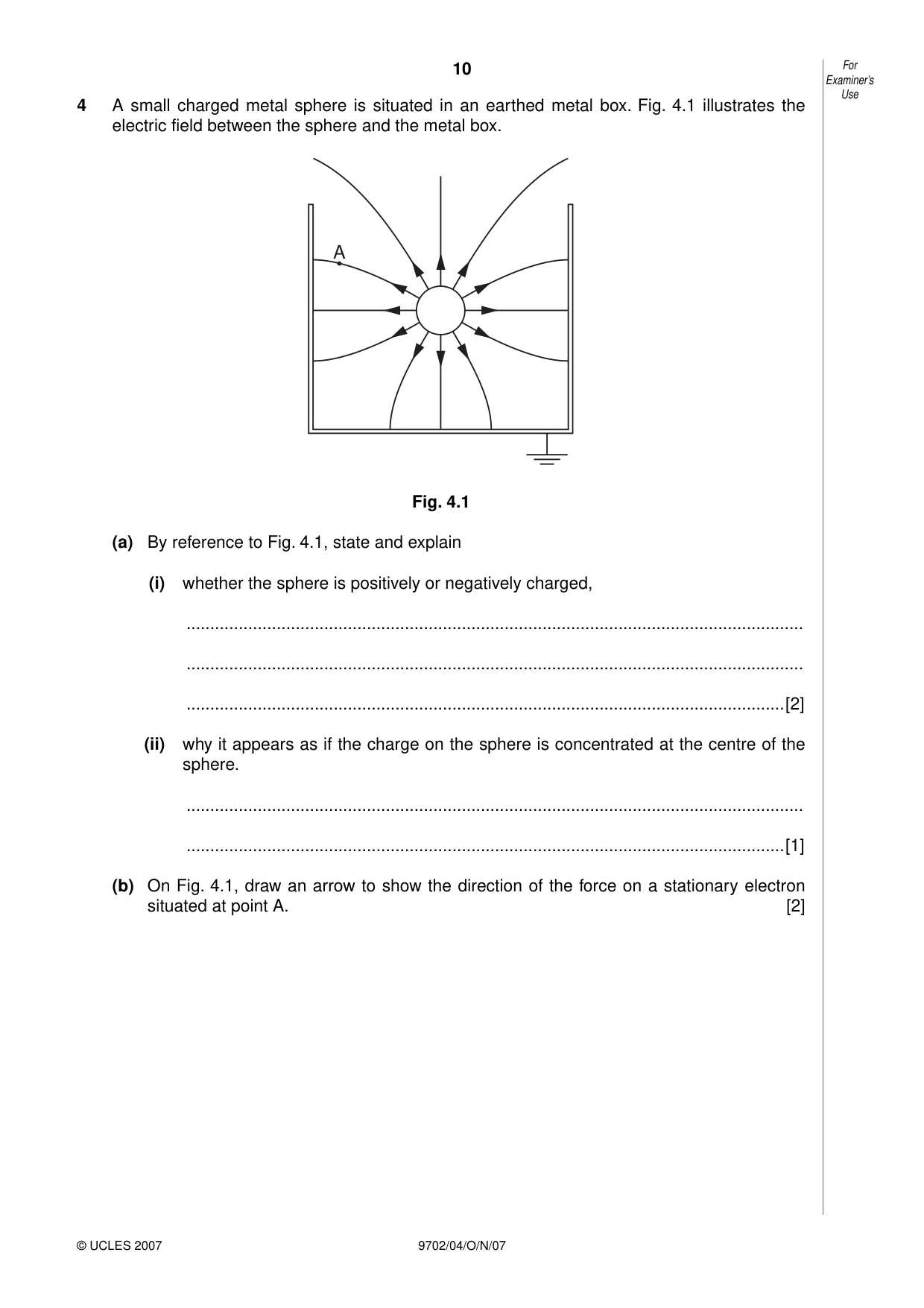
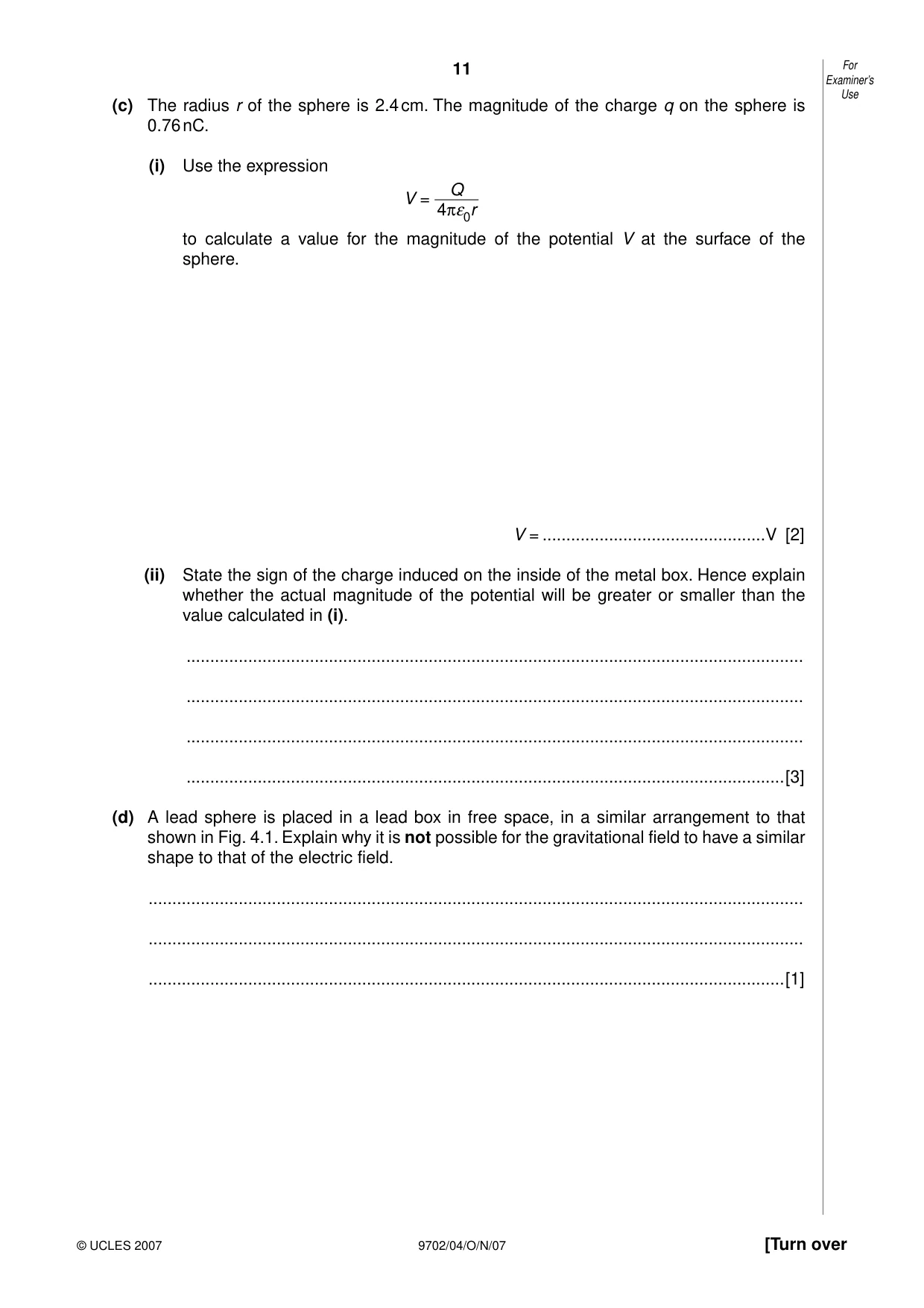
4 A small charged metal sphere is situated in an earthed metal box. Fig. 4.1 illustrates the electric field between the sphere and the metal box. A Fig. 4.1 (a) By reference to Fig. 4.1, state and explain (i) whether the sphere is positively or negatively charged, .................................................................................................................................. .................................................................................................................................. ..............................................................................................................................[2] (ii) why it appears as if the charge on the sphere is concentrated at the centre of the sphere. .................................................................................................................................. ..............................................................................................................................[1] (b) On Fig. 4.1, draw an arrow to show the direction of the force on a stationary electron situated at point A. [2] Examiner’s Use (c) The radius r of the sphere is 2.4 cm. The magnitude of the charge q on the sphere is 0.76 nC. (i) Use the expression Q V = 4πε0r to calculate a value for the magnitude of the potential V at the surface of the sphere. V = ...............................................V [2] (ii) State the sign of the charge induced on the inside of the metal box. Hence explain whether the actual magnitude of the potential will be greater or smaller than the value calculated in (i). .................................................................................................................................. .................................................................................................................................. .................................................................................................................................. ..............................................................................................................................[3] (d) A lead sphere is placed in a lead box in free space, in a similar arrangement to that shown in Fig. 4.1. Explain why it is not possible for the gravitational field to have a similar shape to that of the electric field. .......................................................................................................................................... .......................................................................................................................................... ......................................................................................................................................[1]
Mark scheme: 4 (a) (i) either lines directed away from sphere or lines go from positive to negative or line shows direction of force on positive charge .......................................M1 so positively charged ............................................................................................A1 [2] (ii) either all lines (appear to) radiate from centre or all lines are normal to surface of sphere ...................................................B1 [1] (b) tangent to curve ...........................................................................................................B1 in correct position and direction ...................................................................................B1 [2] (c) (i) V = (0.76 × 10⁻⁹) / (4π × 8.85 × 10-12 × 0.024) .....................................................C1 = 285 V ...........................................................................................................A1 [2] (ii) negative charge is induced on (inside of) box ......................................................M1 formula applies to isolated (point) charge OR less work done moving test charge from infinity ..........................................A1 so potential is lower ..............................................................................................A1 [3] (d) either gravitational field is always attractive or field lines must be directed towards both box and sphere ..............................B1 [1] GCE A/AS LEVEL – October/November 2007 9702 04
Q5 · State one function of capacitors in simple circuits
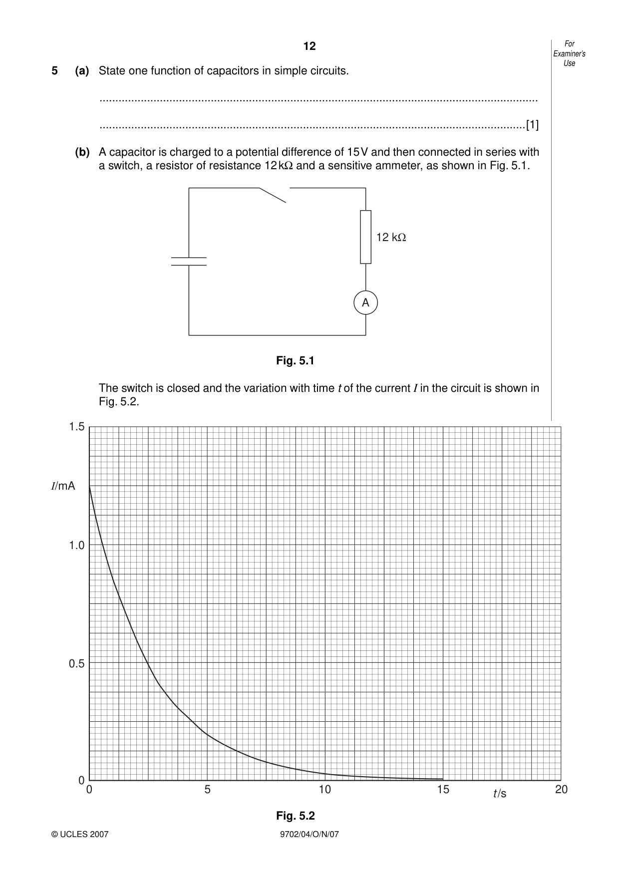
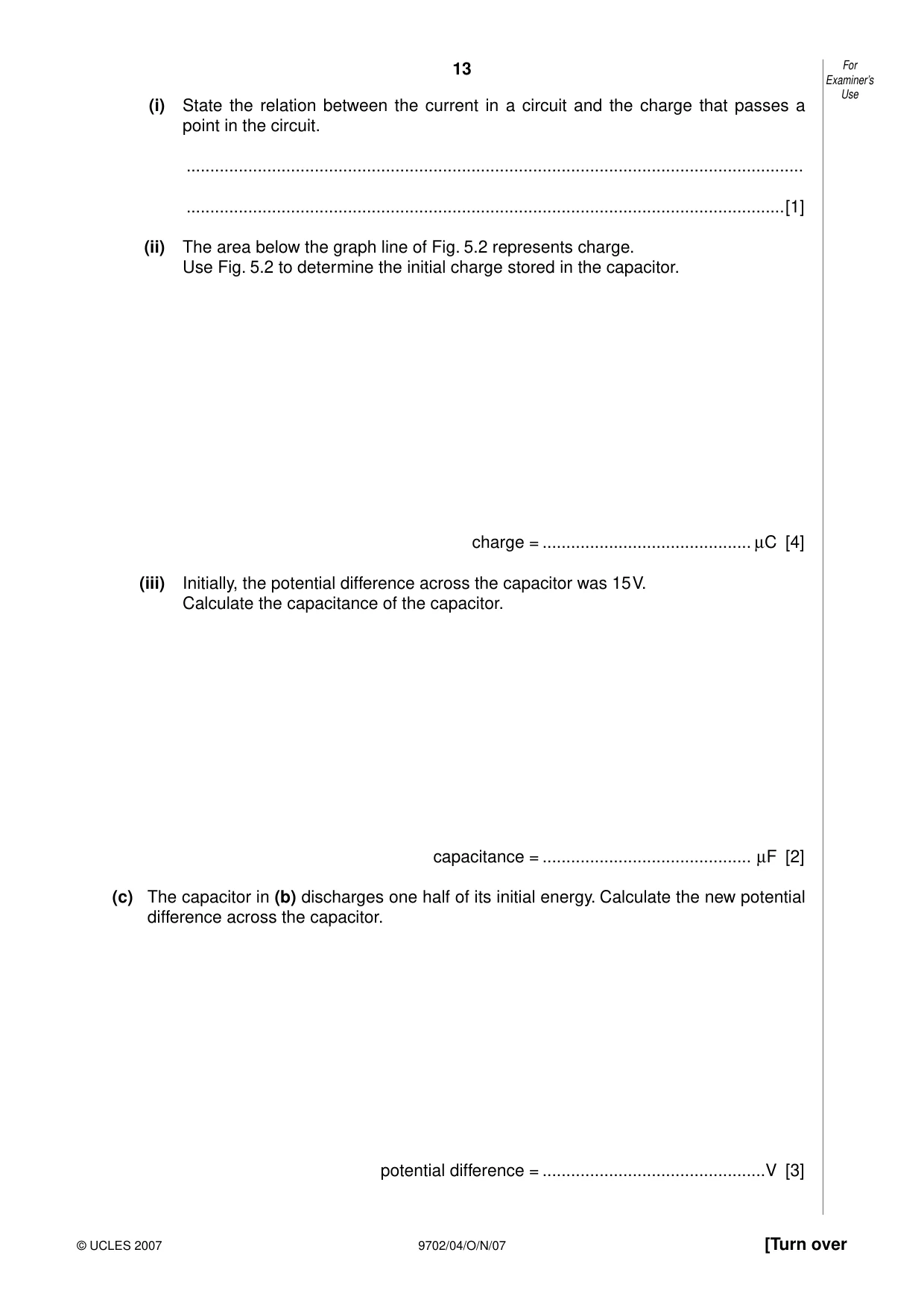
5 (a) State one function of capacitors in simple circuits. .......................................................................................................................................... ......................................................................................................................................[1] (b) A capacitor is charged to a potential difference of 15 V and then connected in series with a switch, a resistor of resistance 12 kΩ and a sensitive ammeter, as shown in Fig. 5.1. 12 kΩ A Fig. 5.1 The switch is closed and the variation with time t of the current I in the circuit is shown in Fig. 5.2. 1.5 I/mA 1.0 0.5 0 0 5 10 15 20 t /s Fig. 5.2 Examiner’s Use (i) State the relation between the current in a circuit and the charge that passes a point in the circuit. .................................................................................................................................. ..............................................................................................................................[1] (ii) The area below the graph line of Fig. 5.2 represents charge. Use Fig. 5.2 to determine the initial charge stored in the capacitor. charge = ............................................ µC [4] (iii) Initially, the potential difference across the capacitor was 15 V. Calculate the capacitance of the capacitor. capacitance = ............................................ µF [2] (c) The capacitor in (b) discharges one half of its initial energy. Calculate the new potential difference across the capacitor. potential difference = ...............................................V [3]
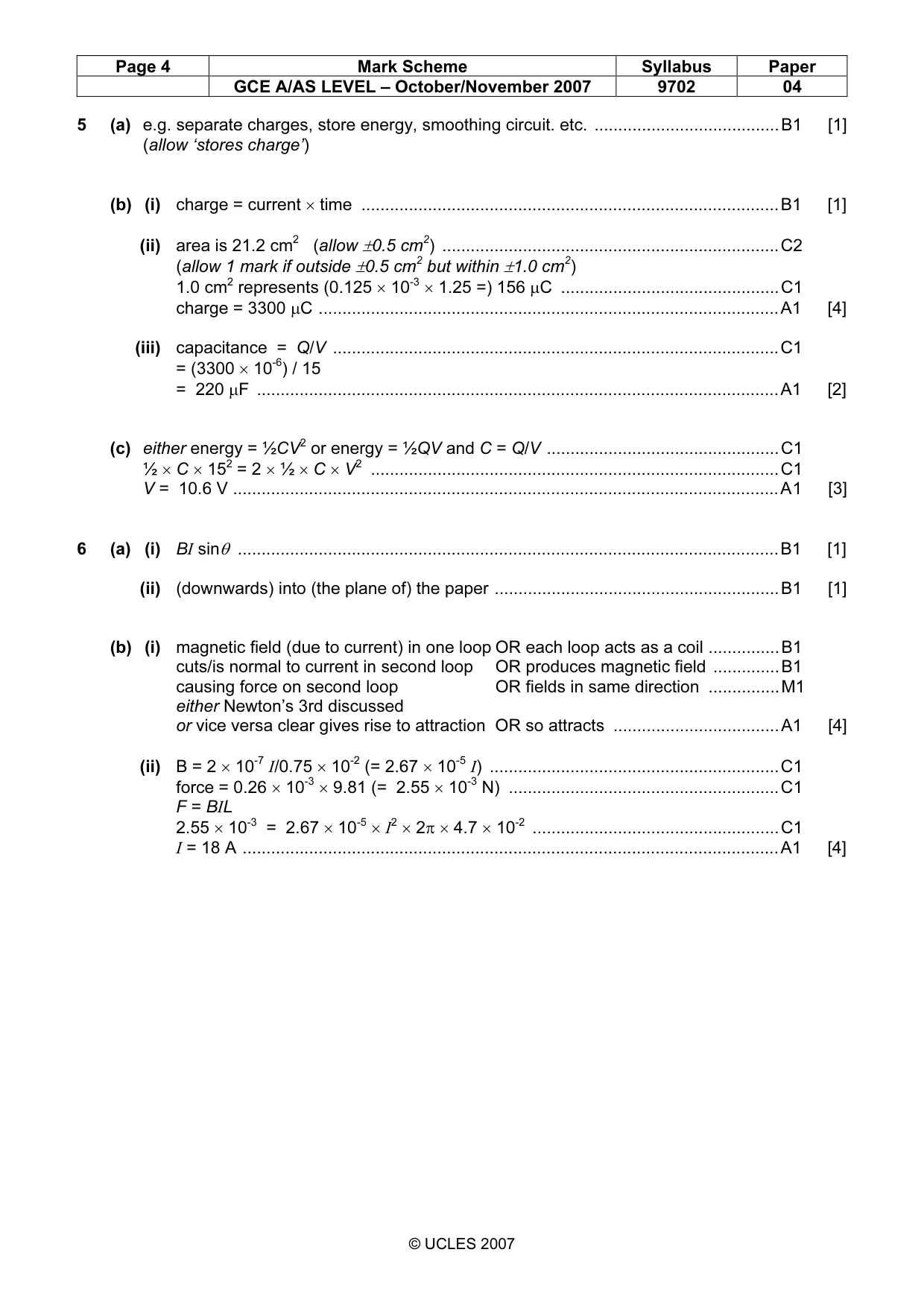
Mark scheme: 5 (a) e.g. separate charges, store energy, smoothing circuit. etc. .......................................B1 [1] (allow ‘stores charge’) (b) (i) charge = current × time ........................................................................................B1 [1] (ii) area is 21.2 cm2 (allow ±0.5 cm2) .......................................................................C2 (allow 1 mark if outside ±0.5 cm2 but within ±1.0 cm2) 1.0 cm2 represents (0.125 × 10-3 × 1.25 =) 156 µC ..............................................C1 charge = 3300 µC .................................................................................................A1 [4] (iii) capacitance = Q/V ..............................................................................................C1 = (3300 × 10-6) / 15 = 220 µF ..............................................................................................................A1 [2] (c) either energy = ½CV2 or energy = ½QV and C = Q/V .................................................C1 ½ × C × 152 = 2 × ½ × C × V2 ......................................................................................C1 V = 10.6 V ...................................................................................................................A1 [3]
Q6 · A straight conductor carrying a current I is at an angle θ to a uniform magnetic field of…
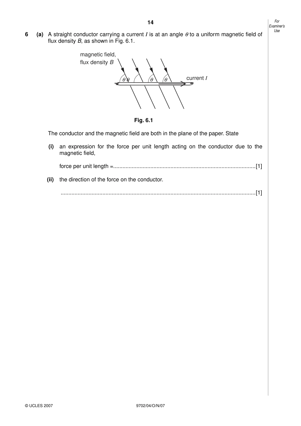
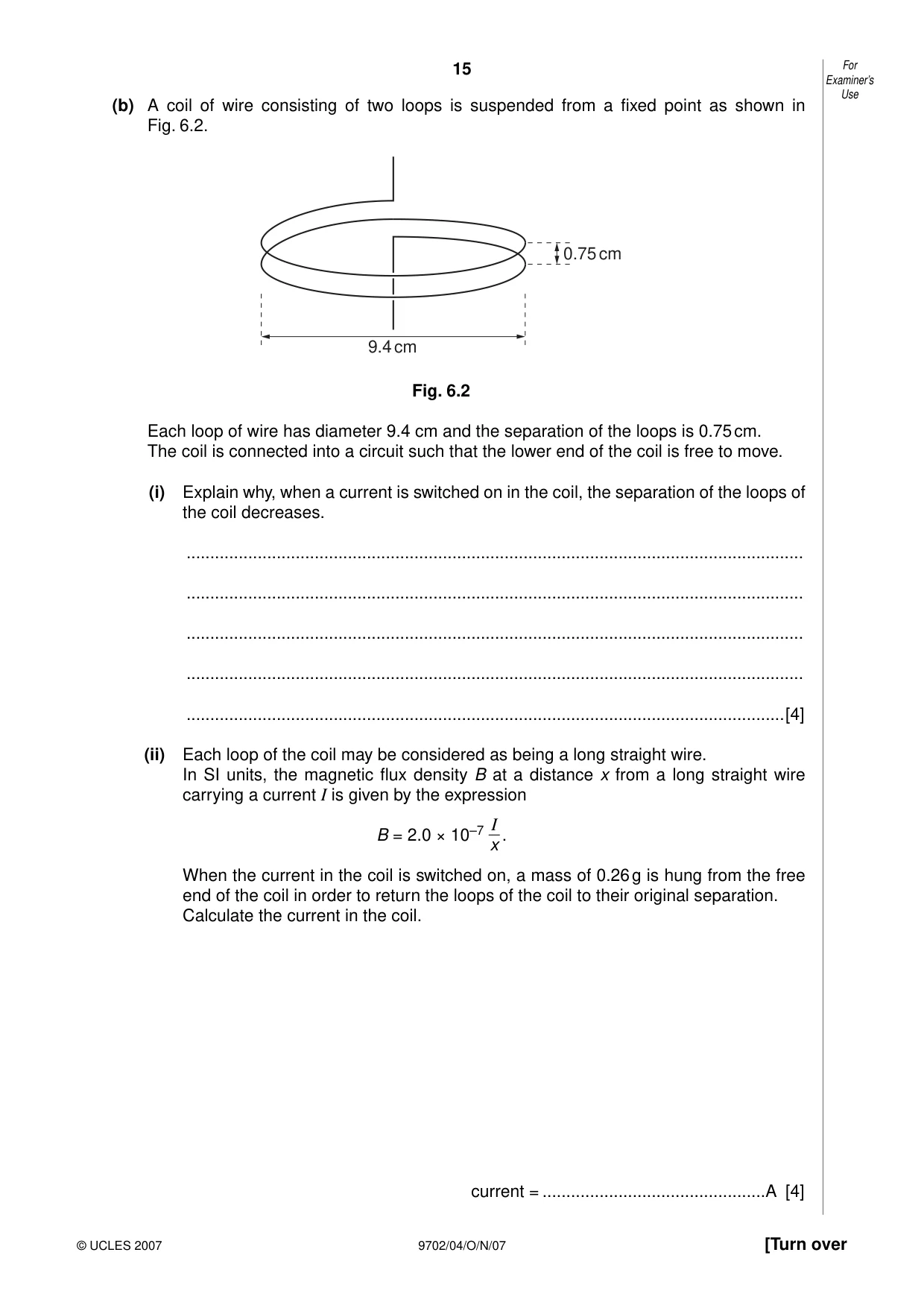
6 (a) A straight conductor carrying a current I is at an angle θ to a uniform magnetic field of flux density B, as shown in Fig. 6.1. magnetic field, flux density B θθ θ θ current I Fig. 6.1 The conductor and the magnetic field are both in the plane of the paper. State (i) an expression for the force per unit length acting on the conductor due to the magnetic field, force per unit length =............................................................................................[1] (ii) the direction of the force on the conductor. ..............................................................................................................................[1] Examiner’s Use (b) A coil of wire consisting of two loops is suspended from a fixed point as shown in Fig. 6.2. 0.75 cm 9.4 cm Fig. 6.2 Each loop of wire has diameter 9.4 cm and the separation of the loops is 0.75 cm. The coil is connected into a circuit such that the lower end of the coil is free to move. (i) Explain why, when a current is switched on in the coil, the separation of the loops of the coil decreases. .................................................................................................................................. .................................................................................................................................. .................................................................................................................................. .................................................................................................................................. ..............................................................................................................................[4] (ii) Each loop of the coil may be considered as being a long straight wire. In SI units, the magnetic flux density B at a distance x from a long straight wire carrying a current I is given by the expression I B = 2.0 × 10⁻⁷ . x When the current in the coil is switched on, a mass of 0.26 g is hung from the free end of the coil in order to return the loops of the coil to their original separation. Calculate the current in the coil. current = ...............................................A [4]
Mark scheme: 6 (a) (i) BI sinθ ..................................................................................................................B1 [1] (ii) (downwards) into (the plane of) the paper ............................................................B1 [1] (b) (i) magnetic field (due to current) in one loop OR each loop acts as a coil ...............B1 cuts/is normal to current in second loop OR produces magnetic field ..............B1 causing force on second loop OR fields in same direction ...............M1 either Newton’s 3rd discussed or vice versa clear gives rise to attraction OR so attracts ...................................A1 [4] (ii) B = 2 × 10⁻⁷ I/0.75 × 10-2 (= 2.67 × 10⁻⁵ I) .............................................................C1 force = 0.26 × 10-3 × 9.81 (= 2.55 × 10⁻³ N) .........................................................C1 F = BIL 2.55 × 10-3 = 2.67 × 10⁻⁵ × I2 × 2π × 4.7 × 10-2 ....................................................C1 I = 18 A .................................................................................................................A1 [4] GCE A/AS LEVEL – October/November 2007 9702 04
Q7 · Explain what is meant by the binding energy of a nucleus
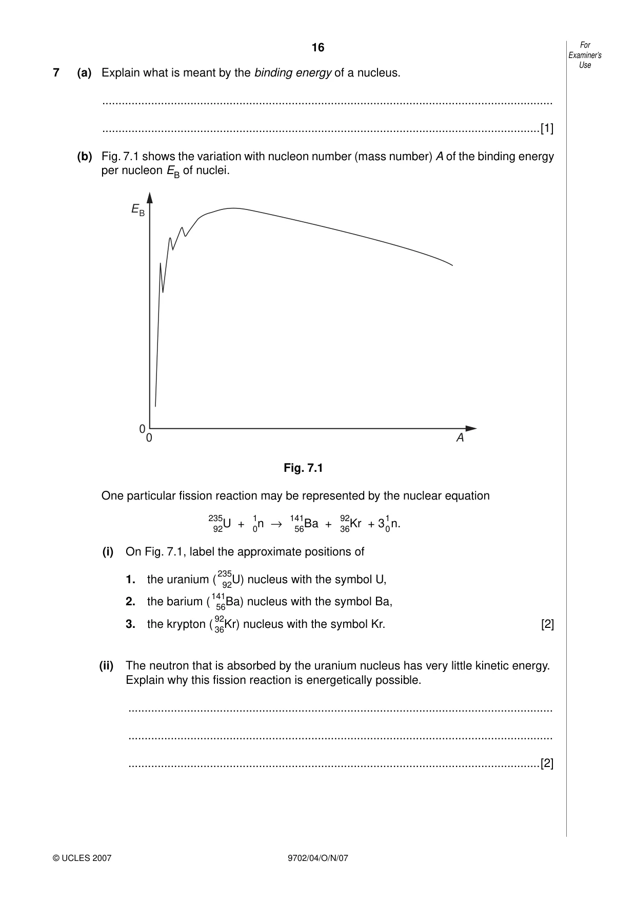
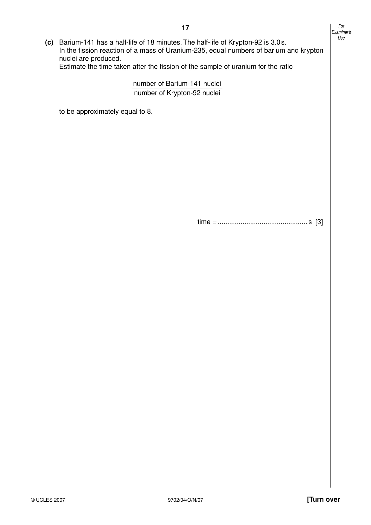
7 (a) Explain what is meant by the binding energy of a nucleus. .......................................................................................................................................... ......................................................................................................................................[1] (b) Fig. 7.1 shows the variation with nucleon number (mass number) A of the binding energy per nucleon EB of nuclei. E B 0 0 A Fig. 7.1 One particular fission reaction may be represented by the nuclear equation 235 1 141 92 92U + 0n → 56Ba + 36Kr + 310n. (i) On Fig. 7.1, label the approximate positions of 1. the uranium (235 nucleus with the symbol U, 92U) 2. the barium (141 nucleus with the symbol Ba, 56Ba) 92 3. the krypton ( 36Kr) nucleus with the symbol Kr. [2] (ii) The neutron that is absorbed by the uranium nucleus has very little kinetic energy. Explain why this fission reaction is energetically possible. .................................................................................................................................. .................................................................................................................................. ..............................................................................................................................[2] Examiner’s Use (c) Barium-141 has a half-life of 18 minutes. The half-life of Krypton-92 is 3.0 s. In the fission reaction of a mass of Uranium-235, equal numbers of barium and krypton nuclei are produced. Estimate the time taken after the fission of the sample of uranium for the ratio number of Barium-141 nuclei number of Krypton-92 nuclei to be approximately equal to 8. time = ............................................... s [3]
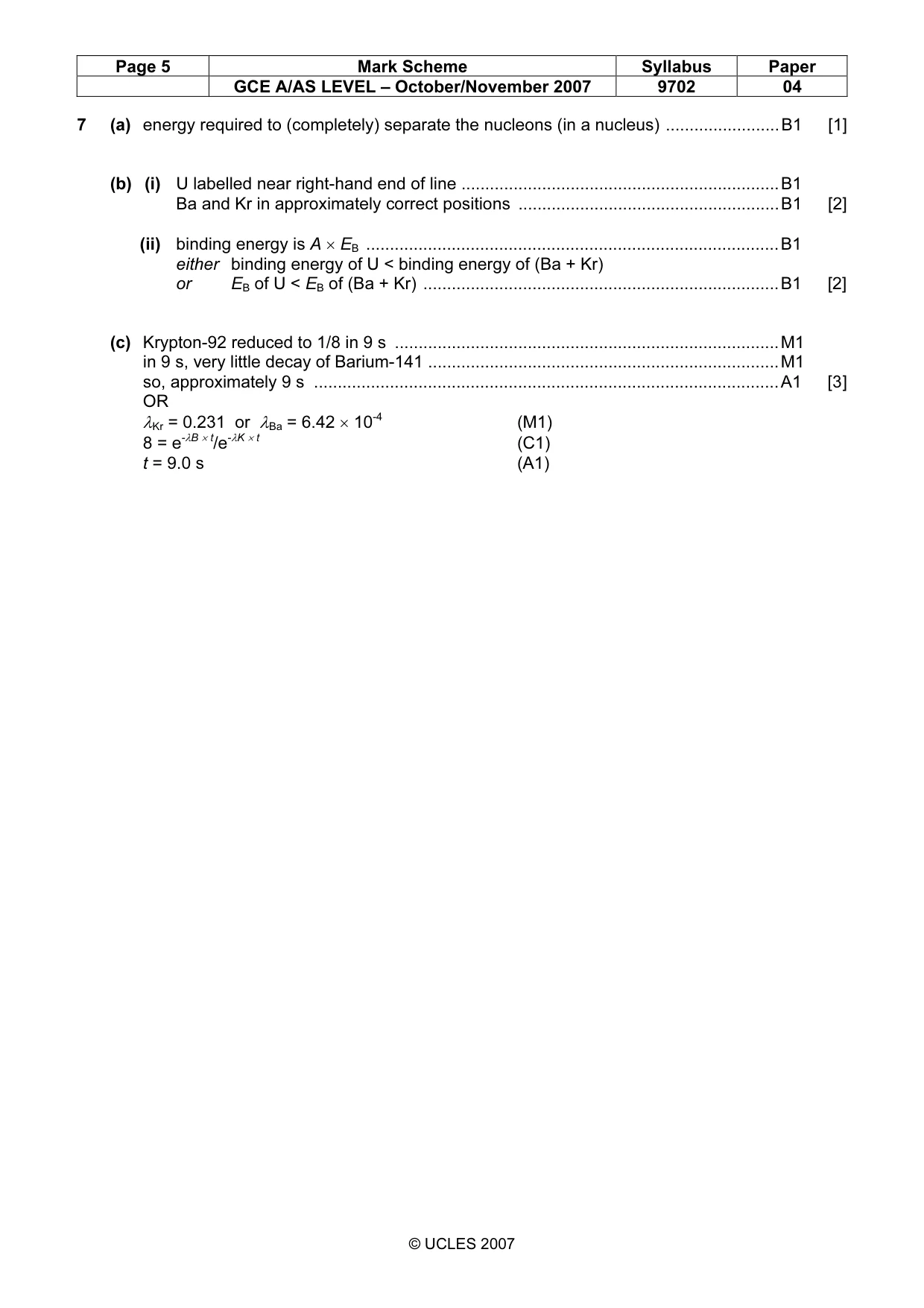
Mark scheme: 7 (a) energy required to (completely) separate the nucleons (in a nucleus) ........................B1 [1] (b) (i) U labelled near right-hand end of line ...................................................................B1 Ba and Kr in approximately correct positions .......................................................B1 [2] (ii) binding energy is A × EB .......................................................................................B1 either binding energy of U < binding energy of (Ba + Kr) or EB of U < EB of (Ba + Kr) ...........................................................................B1 [2] (c) Krypton-92 reduced to 1/8 in 9 s .................................................................................M1 in 9 s, very little decay of Barium-141 ..........................................................................M1 so, approximately 9 s ..................................................................................................A1 [3] OR λKr = 0.231 or λBa = 6.42 × 10⁻⁴ (M1) 8 = e-λB × t/e-λK × t (C1) t = 9.0 s (A1) GCE A/AS LEVEL – October/November 2007 9702 04 Section B
Q8 · A circuit incorporating an ideal operational amplifier (op-amp)
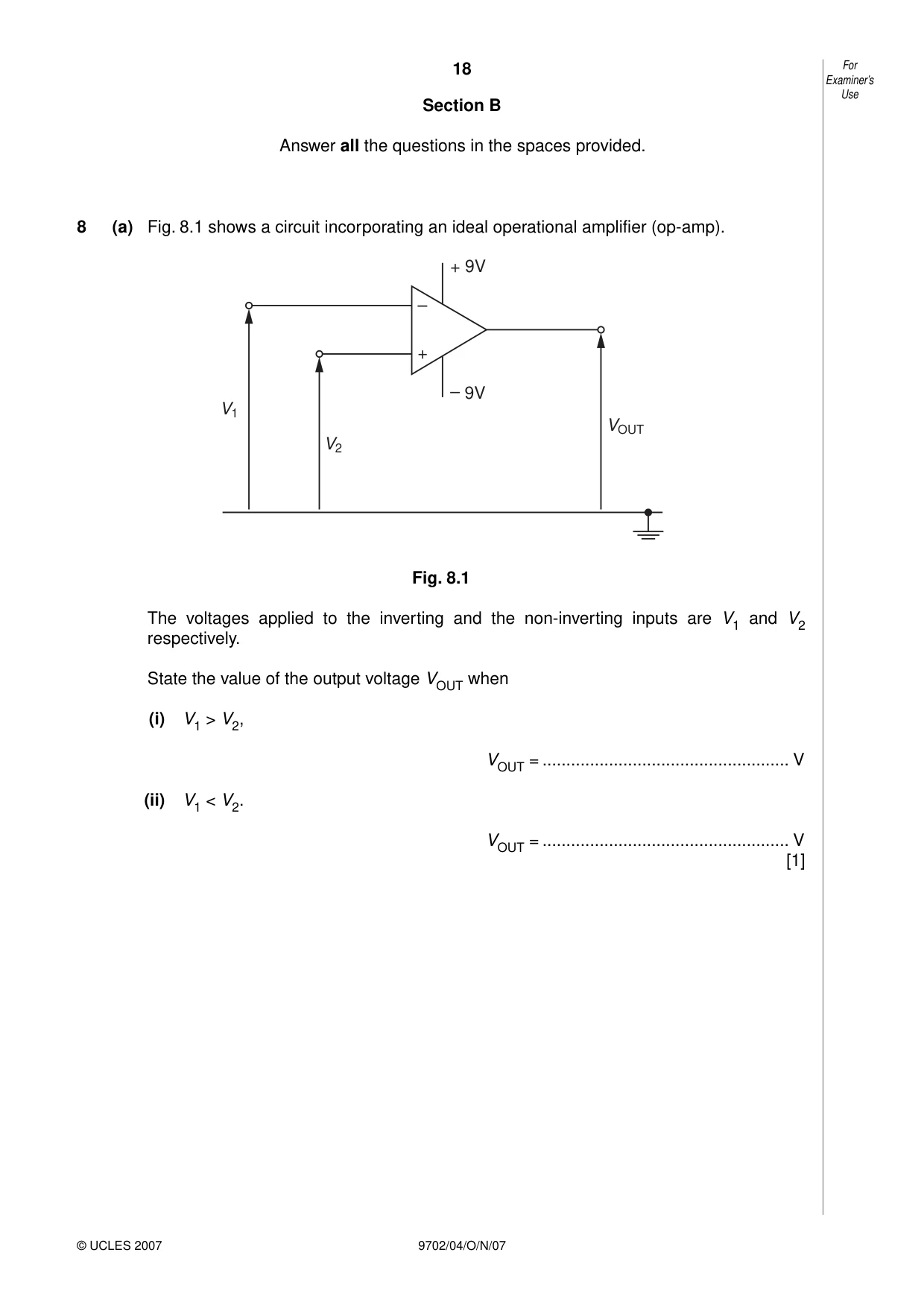
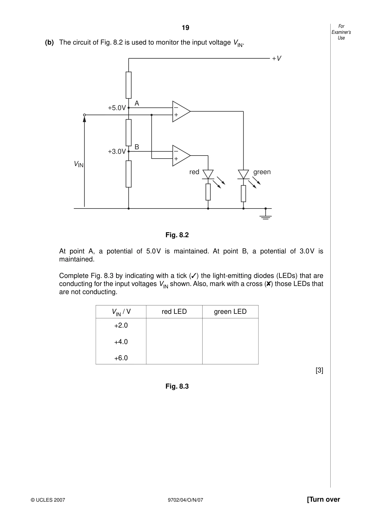
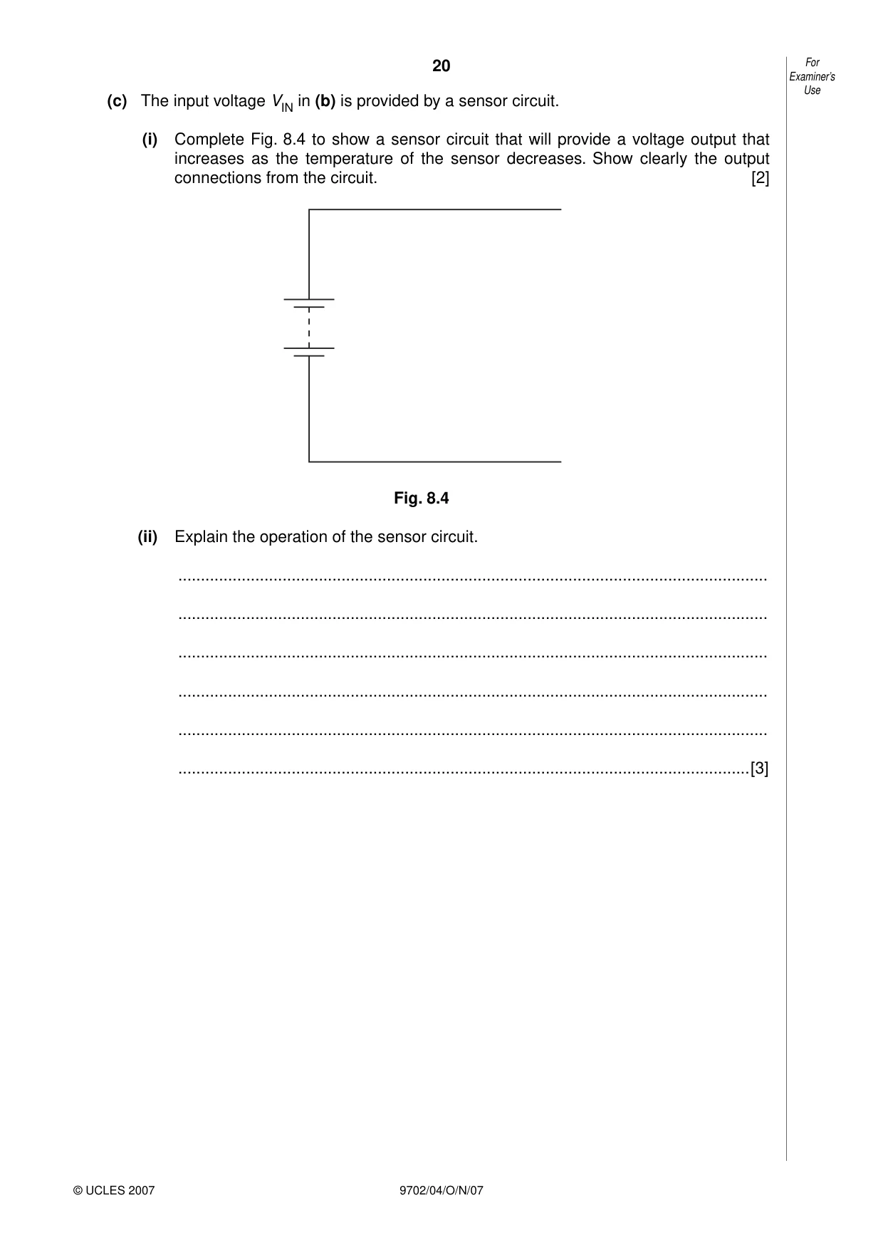
8 (a) Fig. 8.1 shows a circuit incorporating an ideal operational amplifier (op-amp). + 9V – + – 9V V1 VOUT V2 Fig. 8.1 The voltages applied to the inverting and the non-inverting inputs are V1 and V2 respectively. State the value of the output voltage VOUT when (i) V1 > V2, VOUT = .................................................... V (ii) V1 < V2. VOUT = .................................................... V [1] Examiner’s Use (b) The circuit of Fig. 8.2 is used to monitor the input voltage VIN. +V A +5.0V – + B +3.0V – + VIN red green Fig. 8.2 At point A, a potential of 5.0 V is maintained. At point B, a potential of 3.0 V is maintained. Complete Fig. 8.3 by indicating with a tick (✓) the light-emitting diodes (LEDs) that are conducting for the input voltages VIN shown. Also, mark with a cross ( ) those LEDs that are not conducting. VIN / V red LED green LED +2.0 +4.0 +6.0 [3] Fig. 8.3 Examiner’s Use (c) The input voltage VIN in (b) is provided by a sensor circuit. (i) Complete Fig. 8.4 to show a sensor circuit that will provide a voltage output that increases as the temperature of the sensor decreases. Show clearly the output connections from the circuit. [2] Fig. 8.4 (ii) Explain the operation of the sensor circuit. .................................................................................................................................. .................................................................................................................................. .................................................................................................................................. .................................................................................................................................. .................................................................................................................................. ..............................................................................................................................[3]
Mark scheme: 8 (a) (i) - 9 V (ii) + 9 V (both (i) and (ii) correct for the mark) ........................................................B1 [1] (b) ..........................................................................................................................B1 ..........................................................................................................................B1 ..........................................................................................................................B1 [3] (no e.c.f. from (a)) (c) (i) cct: thermistor and resistor in series ………………………………………………...M1 output connections across thermistor ...................................................................A1 [2] (ii) as temperature decreases, thermistor resistance increases ................................B1 p.d. across thermistor = RT / (R + RT) × V ...........................................................M1 as RT increases, output increases ........................................................................A1 [3]
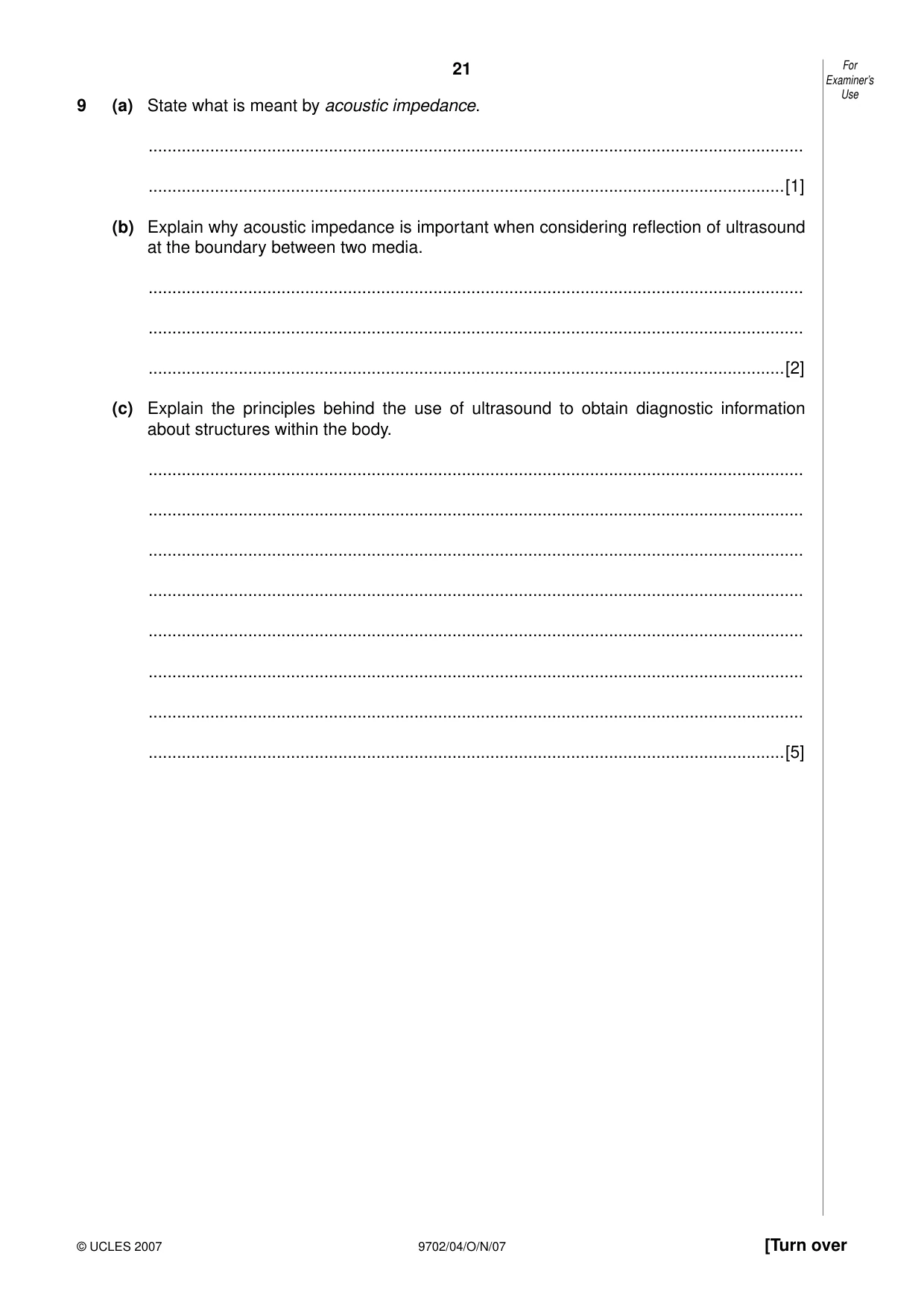
Q9 · State what is meant by acoustic impedance
9 (a) State what is meant by acoustic impedance. .......................................................................................................................................... ......................................................................................................................................[1] (b) Explain why acoustic impedance is important when considering reflection of ultrasound at the boundary between two media. .......................................................................................................................................... .......................................................................................................................................... ......................................................................................................................................[2] (c) Explain the principles behind the use of ultrasound to obtain diagnostic information about structures within the body. .......................................................................................................................................... .......................................................................................................................................... .......................................................................................................................................... .......................................................................................................................................... .......................................................................................................................................... .......................................................................................................................................... .......................................................................................................................................... ......................................................................................................................................[5]
Mark scheme: 9 (a) product of density (of medium) and speed of sound (in medium) ...............................B1 [1] (b) difference in acoustic impedance ................................................................................M1 determines fraction of incident intensity that is reflected/amount of reflection ............................................................................A1 [2] (c) pulse of ultrasound (directed into body) ......................................................................B1 reflected at boundary (between tissues) ......................................................................B1 (reflected pulse is) detected and processed ................................................................B1 time for return of echo gives (information on) depth ....................................................B1 amount of reflection gives information on tissue structures .........................................B1 [5]
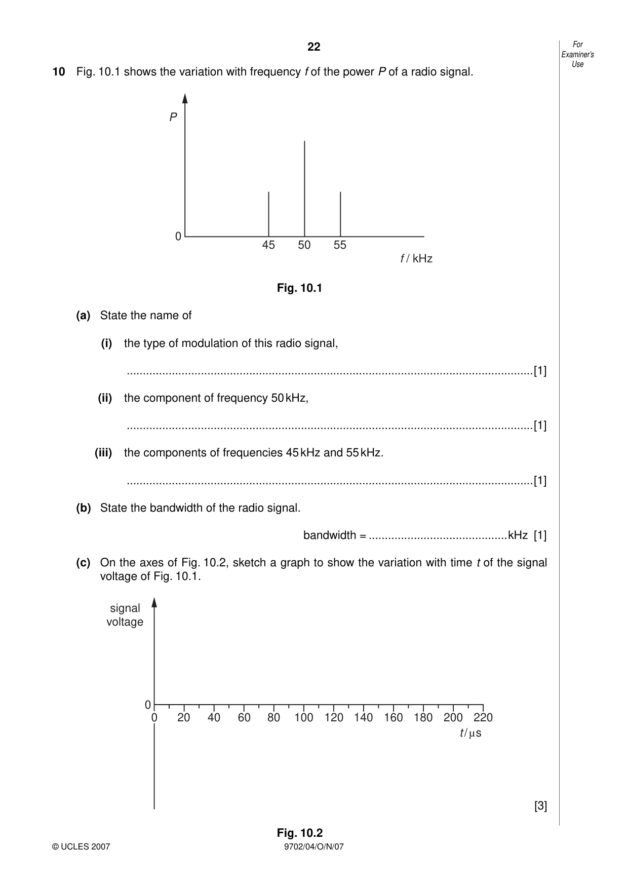
Q10 · The variation with frequency f of the power P of a radio signal
10 Fig. 10.1 shows the variation with frequency f of the power P of a radio signal. P 0 45 50 55 f / kHz Fig. 10.1 (a) State the name of (i) the type of modulation of this radio signal, ..............................................................................................................................[1] (ii) the component of frequency 50 kHz, ..............................................................................................................................[1] (iii) the components of frequencies 45 kHz and 55 kHz. ..............................................................................................................................[1] (b) State the bandwidth of the radio signal. bandwidth = ...........................................kHz [1] (c) On the axes of Fig. 10.2, sketch a graph to show the variation with time t of the signal voltage of Fig. 10.1. signal voltage 0 0 20 40 60 80 100 120 140 160 180 200 220 t / µs [3] Fig. 10.2
Mark scheme: 10 (a) (i) amplitude (modulated) (allow ‘AM’) .....................................................................B1 [1] (ii) carrier (frequency / wave) .....................................................................................B1 [1] (iii) sideband (frequency) ............................................................................................B1 [1] (b) 10 kHz .........................................................................................................................B1 [1] (c) sketch: general shape i.e. any wave that is amplitude modulated ..............................M1 correct period for modulating waveform (200 µs) .......................................................A1 correct period for carrier waveform (20 µs) ................................................................A1 [3] GCE A/AS LEVEL – October/November 2007 9702 04
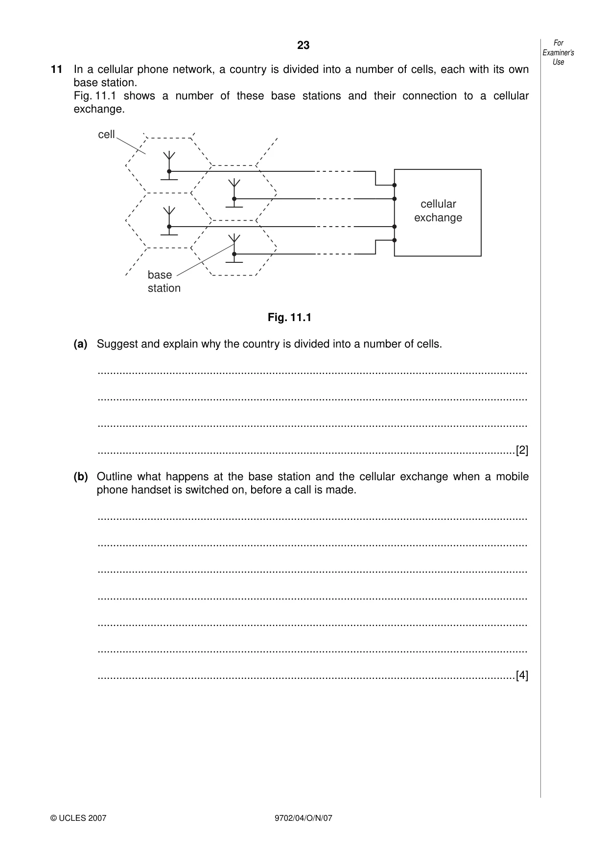
Q11 · In a cellular phone network, a country is divided into a number of cells, each with its…
11 In a cellular phone network, a country is divided into a number of cells, each with its own base station. Fig. 11.1 shows a number of these base stations and their connection to a cellular exchange. cell cellular exchange base station Fig. 11.1 (a) Suggest and explain why the country is divided into a number of cells. .......................................................................................................................................... .......................................................................................................................................... .......................................................................................................................................... ......................................................................................................................................[2] (b) Outline what happens at the base station and the cellular exchange when a mobile phone handset is switched on, before a call is made. .......................................................................................................................................... .......................................................................................................................................... .......................................................................................................................................... .......................................................................................................................................... .......................................................................................................................................... .......................................................................................................................................... ......................................................................................................................................[4]
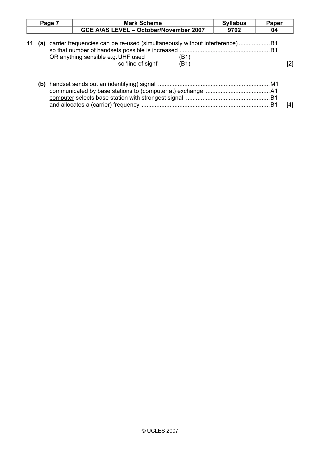
Mark scheme: 11 (a) carrier frequencies can be re-used (simultaneously without interference) ...................B1 so that number of handsets possible is increased .......................................................B1 OR anything sensible e.g. UHF used (B1) so ‘line of sight’ (B1) [2] (b) handset sends out an (identifying) signal ....................................................................M1 communicated by base stations to (computer at) exchange .......................................A1 computer selects base station with strongest signal ...................................................B1 and allocates a (carrier) frequency ..............................................................................B1 [4]
What was in this paper
The subtopics covered by these 11 questions, and how many questions each got. Open one in a new tab to see every Cambridge question on it.
2Characteristics of alternating currents1Discharging a capacitor1Electric fields and field lines1Energy in simple harmonic motion1Force on a current-carrying conductor1Kinetic theory of gases1Mass defect and nuclear binding energy1Physical quantities1Production and use of ultrasound1What you needed in this session
Cambridge’s own grade thresholds for 2007 Oct/Nov, Paper 4 · Variant 1. A higher threshold means an easier paper — the bar moves with how the cohort did.